Elevators Tend to “Fall” Upward, Too
May 1, 2014

A new method for protection against uncontrolled ascending car movement
Gravity and Otis
We all know that according to the law of gravity, objects tend to fall in the down direction. We also know how to calculate the speed (velocity) of falling objects, the impact force of colliding objects and other behaviors of downward-falling objects, yet most people are not aware that elevators can “fall” upward, too.
Gravity and elevators are closely related. In this regard, let us remember the revolutionary solution Elisha Graves Otis presented in 1854. His solution to the problem of a falling elevator involved him instructing his assistant to cut the suspension rope, which caused the activation of the first elevator safety gear. With the successful deployment of the safety gear, Elisha declared “All safe, gentlemen. All safe.” This famous demonstration triggered the beginning of a new era of high-rise buildings supported by safe, high-speed elevators.
Traction-Drive Characteristics
There are several types of elevator drives, and one of the most common elevator drives in use is the traction elevator. This is the type that employs a counterweight to balance the car and load. The friction between the ropes and sheave grooves allows the drive to run the cab without rope slippage. This method is believed to have begun in ancient Egypt.
Traction elevators are distinguished from other lifting types in that they allow high-rise building traffic. Indeed, one cannot imagine high-rise buildings with hydraulic elevators as a vertical-transportation solution. Traction elevators allow movement between floors in a fast, safe and cost-effective way. Another distinguishing feature of traction elevators is that, while they can fall down like hydraulic ones, they can also “fall” upward.
Counterweight
Most elevator riders are not aware that when they are riding a traction elevator up, something heavy rides down, and vice versa: when they ride down, the same object rides up and always at the same speed as the moving car. This heavy counterweight is not only intended to save electrical power (as it allows us to make use of a relatively small electric motor to move a heavy elevator load), it also allows a high-speed elevator to run safely.
We also know that the counterweight is heavier than the empty car. It is customary to calculate the weight of the counterweight relative to the car weight and the elevator load it is designed to carry, in which the weight of the counterweight is equal to the weight of the empty car, plus half the nominal load the cab is designed to carry. Thus, if the cab carries less than half its nominal load, the counterweight is heavier, and the cab tends to move up, while the counterweight moves down. On the other hand, if the load in the car is more than half its duty load, the car tends to move down, and the counterweight moves up.
Brake
Every elevator drive is equipped with a braking device. Older elevators were typically provided with drum brakes, while disk brakes are now more common. Disk brakes are being widely used in machine-room-less elevators, because, unlike drum brakes, disk brakes are considered to be maintenance free, which is highly important with braking systems that cannot be readily adjusted while the elevator is running.
Cost Effectiveness
In a way, elevators are not cost-effective means of transportation, in the sense that they generally react to every call, regardless of the number of passengers waiting in the lobby. Without destination-selection control (DSC), the elevator car answers a call for one person with the same urgency as it would for 20. Moreover, there is no minimum load for elevators, which is contrary to the fact they all have maximum loads. The technology used in existing elevators does not determine how many passengers board the cab for each ride, and the designated power of the motor has almost constant output, which varies slightly according to the load carried in the car.
Modern DSC-enabled systems have the ability to recognize the number of passengers waiting in the lobby with the desire to reach a specific floor; however, this does not prevent the elevator from answering a call for a single passenger with a minimum waiting time. This leads to the conclusion that most of the time (excluding peak time), elevators run with less than half their duty load in the cab, which means that, most of the time, elevator cars tend to “fall” up (rather than down) in the event of a brake or controller failure.
The Problem
We have a presumption that elevator car movement depends solely on its driving machine. Though this is true most of the time, sometimes it is false: since we cannot avoid gravity, the relationship between the drive and elevator car depends on the driving-brake, too. As long as the motor is running under a predetermined speed and according to the intended electric signal, everything is fine. However, once the driving signal disappears and the motor loses its electric power, the motor runs free, the elevator is totally dependent on the brake, and gravity comes into effect. The same motor power that moves the car up or down also provides the necessary resistance to the gravitational force that is being exerted on the car. Once motor power is diminished, the braking means comes into effect to decelerate and arrest the car, preventing it from moving.
The brake is, however, an electromechanical device that may break down for various reasons. In such a case, the brake will not deploy a friction force on the motor shaft to arrest the drive movement, and it certainly cannot hold the car and its load. In this instance, the car is subject to uncontrolled acceleration (either in the up or down direction), accelerating to a high speed and an ultimate impact of the car or counterweight with the buffers or overhead structures.
To avoid this situation, every traction elevator is equipped with a backup device in the form of an overspeed governor (OSG) that reacts to excessive or uncontrolled car speed independently of electric power, and a safety gear (SG), which is activated by the OSG and is capable of stopping and holding the car with its load on the guide rails.
SG
The SG is actually a car brake intended to clamp and hold the car on its guide rails in the case of uncontrolled or unintended car movement as a result of either excessive speed resulting from suspension failure, machine shaft breakage, machine brake failure or any unintended car movement with open door. The latter two are the most common failures.
The majority of existing elevators are equipped with only a downward SG. However, as a result of past experiences of uncontrolled ascending elevators, elevator codes have been changed to include ascending car overspeed protection, as well as unintended-motion protection (with doors open) in either direction.
Many manufacturers have developed low-cost bidirectional SGs that can easily be implemented into new installations. These types of SGs are activated by a single OSG designed to trip in both directions. Although such an SG has a limited capacity to carry during its activation, it is considered to be a cost-effective, high-quality, safe solution. Yet, the problem of protecting existing elevators from uncontrolled upward acceleration remains. Replacing an existing unidirectional safety gear with a bidirectional may range from impossible to very complicated and expensive. Even add-on devices to resolve the problem fall into the latter category and are dependent on electric power.
The Solution
As mentioned, an additional SG must be employed to provide safe protection for upward movement. Luckily, elevators have simple mechanical structures that allow us to add a new, separate SG for existing elevators. The only problem remaining is how to activate this SG cost effectively. In other words, how can the new SG be activated with the existing OSG, or, how can two separate SGs installed in the same elevator and acting in opposite directions be activated using the existing OSG, independent of electric power?
It is a relatively easy task to design an up-direction safety gear to be installed on the car frame incorporating a guide shoe, to replace the existing guide shoe and be installed as a replacement component. Of course, the new SG can be activated by an additional new OSG, but this is an expensive and complicated solution. For that reason, your author devised a new method of using a single OSG to activate two separate SGs that act in opposite directions to each other that are installed on the same elevator car. This will allow the addition of a simple, low-cost SG for upward protection on most existing elevators.
The solution suggested here may serve both as a low-cost add-on SG for existing elevators, and for a problem involving high-speed elevators. Moreover, it can be applied to elevators with heavy loads that cannot make use of small bidirectional SGs with limited allowable capacity. It involves a new method using a single OSG to activate two separate safety gears: one for the upward and the other for the downward direction, installed on the same elevator.
How It Works
Currently, a single OSG employs only one SG, either unidirectional or bidirectional. This traditional SG is rigidly connected to the OSG rope, both ends of which are connected to the SG lever arm, which causes the rope to move in conjunction with the car movement on its top and bottom sheaves. Once the top sheave is locked, the rope stops its movement; thus, the lever arm is blocked, and the continuing movement of the car activates the safety gear.
Such a connection cannot be accommodated when it comes to the activation of two SGs with a single OSG. The reason for this limitation can be illustrated by imagining tying a rope to a doorknob that rotates only clockwise, then connecting the same rope (above the knobs) to another doorknob that rotates only counterclockwise. It is clear that whichever doorknob rotates will break the other one, which is why both SGs cannot be rigidly connected to the same OSG rope — simply because the OSG arm moves in opposite directions.
The downward SG lever normally moves up during SG activation, while the upward SG lever must move down during activation. To overcome this limitation, your author has designed a movable connection of the levers and OSG rope. In this solution, each lever end is designed to include a hollow shape (such as a ring) through which the OSG rope passes, and both ends of the rope are connected between or outside of these two ring areas; thus, the rope is not connected to either lever. In addition, a mechanical stopper is attached onto the rope above the upper and under the lower ring. The stopper’s dimensions are greater than the rings’ diameter; thus, the stopper cannot pass through the ring.
During normal operation, car movement creates a minor impact between a stopper and its ring. When it moves up, the upper ring collides with the upper stopper, causing the rope to move up with the car. The same happens when the car moves down: the bottom ring collides with the bottom stopper and moves the rope down, along with the car’s motion.
Upon OSG tripping, the rope motion stops, so that when the car moves down, the downward stopper blocks the bottom ring movement, thus forcing the lever arm to move up to engage the guide rail and block car movement. At the same time, the upper lever arm continues its motion along with the car movement with no interference, which increases the distance between the upper ring and its stopper. The same happens when the car moves up: the upper stopper blocks the upper lever arm to force the lever arm to move down to engage the guide rail and block the car. At the same time, the bottom lever arm continues its motion along with the car movement with no interference. Hence, the distance between the bottom ring and its downward stopper increases. In both cases, no harm to the lever arms occurs, and each SG works independently.
Usually, the lever arm is equipped with a tension spring to ensure its neutral position to avoid accidental safety-gear activation. The force the spring exerts on the lever arm must be less than the friction between the OSG rope and OSG sheave grooves. Every car movement is sensed by this spring, but since there is no friction during normal operation, the spring motion is negligible. In short, under normal operation, the spring resists the lever arm movement, preventing SG activation.
For arrangements in which the additional SG is installed at the top of the car frame, it is necessary to evaluate the loads and determine the stresses imposed on the car frame during safety application. The frame may not have been designed to withstand such stresses within the margins of safety required by code. The need for such calculations can be avoided by installing the upper SG at the bottom of the car frame under the downward SG. In this case, the arrangement of the stopper’s position will be changed to be between the SG lever arms (Figure 5).
In this case, when the car moves down for tripping, the upper lever arm is blocked by the upper stopper. Located under the lever arm, it forces the arm to move up to engage the guide rail and block car movement. At the same time, the bottom lever arm moves down, increasing its distance from its stopper. The opposite happens when the car moves up for tripping with the bottom lever arm.
These arrangements led to your author’s construction of a pair of double-SG arrangements on each car frame (Figure 6). This may be useful to reduce both friction during SG activation in high-speed elevators and guide-rail damage. Once two separate safety gears are employed at the correct distance apart, friction on the same point is reduced by 50%, thus reducing guide-rail heating during SG activation.
Hence, with this method, it is possible to activate every possible combination, including a double bidirectional SG constructed of two separate SGs (up and down), which can consist of an upward SG either under or above the downward SG. It can also be employed in a combination of usages (Figure 7).
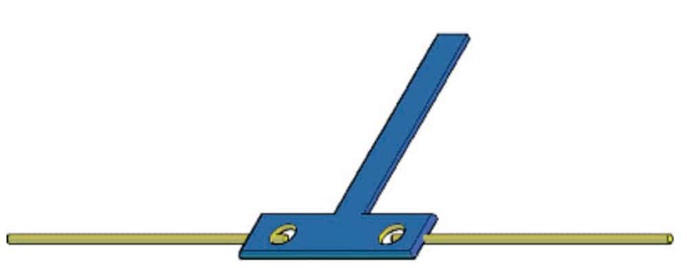
Figure 2: The rigid connection of an SG to the OSG rope 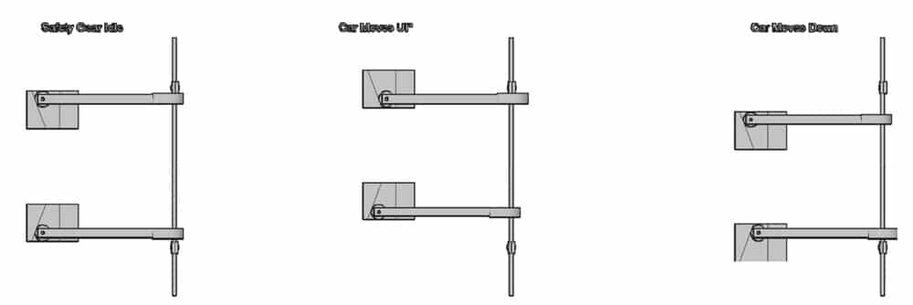
Figure 3: The three known cases/situations in which the SG may be found: (l-r) idle, tripping up and tripping down. 
Figure 4: In this arrangement, where the upward SG is on top and the downward SG is on bottom, the stopper attached to the OSG rope is outside the lever-arm zone. 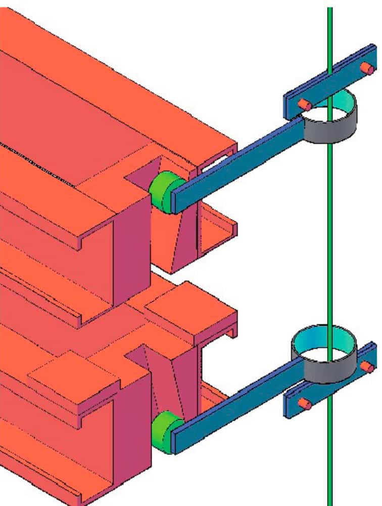
Figure 5 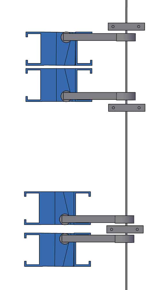
Figure 6: Blocker arrangement for double safety on top and bottom: (top to bottom) upward above downward and downward above upward
Get more of Elevator World. Sign up for our free e-newsletter.


