Benefits of modernization projects for escalator and moving walk drives
Most vertical-transportation industry stakeholders — and people in general — are more and more committed to protecting the environment. Thus, responsible and e–cient use of energy is an important element to be considered.
From a wider perspective, we must look at lifecycle assessment (LCA), beginning with the initial design stage for new products. However, this should be done for product modernization, too, to better understand the varied benefits/ consequences of machine upgrades. We will not present a complete LCA here but will present the most interesting advantages of modernizing escalator and moving walk drives with variable-voltage and speed controllers, in terms of energy and other operational cost savings, as well as product- lifetime impact.
Options for 10-15-Year-Old Units
Escalators and moving walks made in the last 10-15 years often have variable-voltage, variable-frequency (VVVF) drives/inverters. Such machines normally switch from their rated speed of 0.5 mps to 0.2 mps during periods of passenger absence. Passenger detection is normally carried out by a photocell light-beam sensor in the skirting near the comb intersection line (where the steps begin to move). This is known as “nominal speed — low speed” (NL). Only a relatively small portion of those existing escalators are equipped with sensors that can detect people 1.3-1.8 m before boarding.
This is a requirement, from EN 115, for the units to completely stop and wait for the next batch of passengers to come. This is known as “nominal speed — low speed — standby” (NLS).
So, stakeholders responsible for the operation of those machines might consider switching from NL to NLS, which, as described above, is normally possible by adding auto-reflecting photocells or radar sensors to nearby handrail inlets (either integrated on the inlets or fixed to floorplates nearby).
Options for 15-30-Year-Old Units
Units in this age segment normally operate at nominal speed (N) all the time. An escalator can be modernized to either NL or NLS operation. While it can also be modernized to NS operation, that will not be presented here, as NS operation has some disadvantages due to stress on mechanical components during start/stop processes.
This could be mitigated by an NS soft starter, but costs then approach those of more powerful upgrades based on variable-speed drives, like NL and NLS. This is clearly the age segment with the biggest energy and operational savings potentials.
Options for 30-Plus-Year-Old Units
A different modernization strategy might be made for escalators older than 30 years. It would normally include a complete control- system upgrade, full refurbishment or substitution.
How to Make the Best Decision
The best decision will first be determined by passenger tra–c characteristics, in terms of quantity and type (small and continuous passenger entry flow versus large, periodic passenger entry batches).
We will know how much energy will be saved after each type of modernization (N to NL, N to NLS and NL to NLS) with ±10% precision and the same for traveled-distance reductions, which is very strongly related to operational costs and remaining life.
A note on regenerative drives: as there are very few moments when regeneration occurs, your author estimates regeneration watts per hour within a day are not significant compared to the energy consumption of a whole journey.
Passenger Load Measurement Example
There are several methods for load and tra–c registering, and the one with which your author is most familiar is by active power measurement using a three-phase power analyzer.
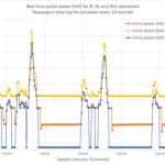
Assume Escalator A is a mid-high-tra–c escalator equipped with a 30-kW motor. From Figure 1’s active power analysis graph, we discover something applicable, in general, for escalators and moving walks:
- Motors will work during tra–c peaks at 30-50% of their rated capacity due to the fact that motors are normally sized for transportation of two passengers per step, while reality shows in tra–c peaks there is one passenger every two steps on the right side (“static passengers”) and one passenger every 3 or 4 steps on the left side who walk on the steps.
- During normal hours, motors operate at 15-25% of their capacity.
- During low tra–c hours, this capacity is only 10-15%.
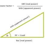
Power Factor
One consequence from the above is that motor power factor is very low for start-delta escalators running all the time at N. This results in high resistive and magnetic motor loses, as it is operating at 0.5 mps with an input voltage of 400 ACV at 50 Hz, while torque demand is very low compared to rated capacity.
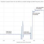
Power factor is as low as 0.1-0.2, and the high reactive power is overloading the electric supply lines, causing resistive losses on the supply side, too. Figure 3 shows power-factor differences between star-delta- (N) and VVVF-controlled identical motors in both up and down directions.
The VVVF drive (inverter) improves power factor. If the internal inverter’s eco mode is activated, voltage feed to the motor will be adjusted to the required torque. This means saving energy even at constant nominal speed, approximately 400 W for a 15-kW motor and 300 W for an 11 kW one. These very significant savings are equivalent to 15% of total motor power consumption at 0.5 mps (no passenger load).
Traffic Calculation From Active Power Data
If active power data is carefully processed, we can obtain the number of passengers traveling in the escalator with decent precision. We can also obtain information on escalator loaded/ unloaded status with high precision. This will be helpful for simulation of different energy-saving options like NL and NLS. Even if we have data from an escalator in NL operation, we can determine the tra–c and power needed if the inverter is broken and/or bypassed, degrading to N operation.
The example escalator A incorporates a VVVF drive (inverter) realized by active power decreasing to 2.3 kW after no passenger entrance in the last three points (30 s.).
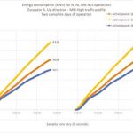
We can understand the savings for each strategy are not the same from the following data:
Escalator A (up direction, mid-high tra–c profile):
- From N to NL: daily energy savings of 17 kWh (25% over N)
- From NL to NLS: daily energy savings of 10 kWh (15% over N)
- From N to NLS: daily energy savings of 27 kWh (40% over N) Escalator B (down direction, low tra–c profile):
- From N to NL: daily energy savings of 17 kWh (38% over N)
- From NL to NLS: daily energy savings of 18 kWh (41% over N)
- From N to NLS: daily energy savings of 35 kWh (79% over N)
The savings are strongly dependent on escalator tra–c (number of passengers) and how they enter (a small and continuous flow versus large, periodic batches). An example of small and semi- continuous passenger flow is a downward escalator between street level and station hall in an underground system, while an example of large, periodic batches would be an upward escalator from train platform to hall.
Making the Decision
Once we know how many kilowatt-hours and how many kilometers per day we will save because of the simulation of different energy and operational saving strategies, we are in a good position to translate them to economic and environmental protection (carbon footprint reduction) figures. We will also be in a good position to calculate if we managed to improve energy classification according to ISO 25754:3-2015. Combined, this will help us make the best decision about modernization strategy.
Savings are very strongly linked to specific tra–c patterns for each unit, height inclination, and speed of the escalator or moving walk. Therefore, it is suggested to not use standard percentage figures for savings but, instead, follow a good tra–c analysis based on real escalator or moving walk power measurements within a week, or at least one working day and a weekend day.
- Figure 1
- Figure 2
- Figure 3
- Figure 4: Fifty minutes of active power and traffi c calculation during peak traffi c hours (escalator A)
- Figure 5: Fifty minutes of active power and traffi c calculation during low traffi c hours (escalator A)
- Figure 6: Simulation of “N” operation and “NLS” operation from “NL”
- Figure 7: Energy consumption during two whole journeys (escalator A)
- Figure 8: Energy consumption during one journey (escalator B)
- Figure 9: Daily distance traveled by escalator A (kilometers)
- Figure10: Daily distance traveled by escalator B (kilometers
Get more of Elevator World. Sign up for our free e-newsletter.
