Energy Efficient Modernisation of Hydraulic Drives
May 1, 2011

Tony Aschwanden and Conradin Jost
Bucher Hydraulics AG, Switzerland
This paper was presented at ![]() Lucerne 2010, the International Congress on Vertical Transportation Technologies and first published in IAEE book Elevator Technology 18, edited by A. Lustig. It is a reprint with permission from the International Association of Elevator Engineers
Lucerne 2010, the International Congress on Vertical Transportation Technologies and first published in IAEE book Elevator Technology 18, edited by A. Lustig. It is a reprint with permission from the International Association of Elevator Engineers ![]() (website: www.elevcon.com). This paper is an exact reprintand has not been edited by ELEVATOR WORLD.
(website: www.elevcon.com). This paper is an exact reprintand has not been edited by ELEVATOR WORLD.
Key Words: Energy efficiency, energy saving, modernisation, smart hydraulics, electronically controlled hydraulic valve, hydraulic inverter technology, stand-by consumption
ABSTRACT
Modernisation and energy efficiency are two of the dominant topics for the future in the lift industry. Bucher Hydraulics has recognised the signs of the times since the beginning and can already provide mature and well-established products today. However, with a better understanding of the demand in the modernisation marked new products are developed by Bucher Hydraulics. This means, optimised in energy efficiency with a special focus on best price performance ratio. The result is a so called “Compact VF” solution which can be also combined with “Multikit” for a step by step modernisation of the hydraulic lift facility. This will help to reduce energy consumption substantial for over 1.2 million older hydraulic lifts in operation (typically older than 20 years) by a minimal cost burden for the end-owner.
1 INTRODUCTION
Safety and accessibility have been the main topics in the lift industry for many years. Now, environmental issues are coming in focus since the “Kyoto protocol” was established. Greatest effort was made on energy efficiency of the lift facility and most manufacturers have invented interesting solutions to reduce energy consumption substantial. Also, Bucher Hydraulics is aware of this trend since the beginning and is making
a great effort on developing energy efficient hydraulic drive systems. To reduce energy consumption of currently installed lifts, modernisation is therefore the main key. It is often forgotten that a significant part of the installed lift facilities which are older than 20 years are hydraulic lifts. Therefore, only an energy efficient hydraulic power unit can be taken into account for an ecologically worthwhile modernisation. An additional fact is also, that greatest numbers of installed lifts are in the residential sector which has special market requirements. This means; limited application rang (e.g. travel, payload, speed etc.), normally low usage intensity and finally very cost sensitive and therefore a step by step modernisation is preferred to spread costs over several years. In this paper the lift market for energy efficient modernisation is analysed and the possible potential is demonstrated. Further, a short introduction is given in the state of the art of hydraulic drives for a better understanding of the technology. The last part shows the product development of an energy efficient power unit which is called “Compact VF” for best price performance ratio to fulfil the above described marked demand. Further this solution can be combined with “Multikit” for a step by step modernisation.
2 MARKET ANALYSIS
There have been a lot of market analyses to determine the need for modernisation of older lift facilities. A very comprehensive analysis has been made by the Intelligent European Energy organisation with the so called “E4 Project”. In cooperation with four Universities and the European Lift Association (ELA) a significant appraisal of the European lift market has been made covering the potential for energy efficient lift facilities. Continued
2.1 Facts and figures
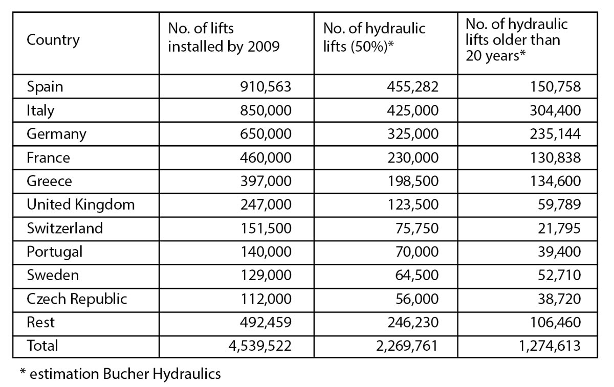
It is challenging to get a clear overview of the world wide lift market and there are a multitude statistics which cover this issue. A reliable source for Europe is the ELA statistic from the year 2009 covering most industrialised European countries. Table 1 shows that approx. over 4.5 million lifts are in operation. By a realistic estimation, that 50% of overall are hydraulics and more than half of them are older than 20 years, ca. 1.2 million hydraulic lifts have a real need for modernisation. A detailed allocation of the type of lifts gives Figure 1.
2.2 Guidelines and targets toward energy efficient lift facilities
The EU is pushing the industry to reduce the total energy consumption in all fields by 20% by 2020. In this context, VDI 4707 which has been realised beginning 2009 and the preliminary work for an ISO-code (25745-1) will have a considerable impact on the lift industry. Further, the European EPB directive (Energy Performance of Buildings – directive 2002/91/EC), which is presently under revision, advises national governments and public authorities to organise a certification process and revision thereof, to encourage good energy management. It includes building renovations of course and the introduction of new and alternative energy systems and solutions.
2.3 Market structure
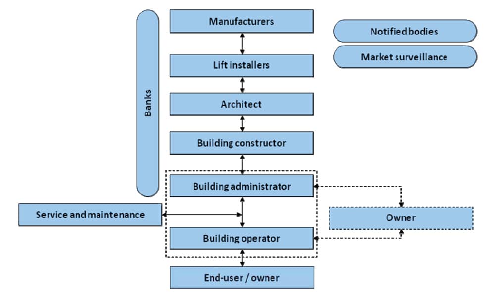
Lift owners in most cases are not aware of the circumstance that they have mature lift facilities in their properties and therefore a big lack of information regarding the possibilities of energy efficient modernisation exist. Manufacturers can develop and also promote energy efficient solutions covering the latest guidelines but they will never have such a close relationship as lift installers or service companies have to the owner. Hence, this group is very important to advise end-users of the possibility of energy efficient modernisation. Further, it is also a chance to growth in a market as described above with a potential of 1.2 million lifts. To accelerate energy efficient modernisation notified bodies and market surveillances can inform or make calculations about the energy saving potential on the owners existing properties. Figure 2 shows the typical market structure in the lift industry.
3 STAT OF THE ART OF HYDRAULIC DRIVES
Bucher Hydraulics’ lift division, introduced 30 years ago the unique electronically controlled lift valve “LRV”. This lift valve is still the benchmark for a highly reliable hydraulic control, providing unsurpassed riding comfort, latest update in safety and energy efficiency. The next step in development is the “intelligent” valve called “iValve” with a self adjusting function and options for remote access and condition monitoring.
3.1 Electronically controlled lift valve
The good genes of this electronically controlled lift valve lead to several incomparable developments within the hydraulic drive market. All this effort has been spent in order to increase the efficiency and to guarantee perfect ride comfort independent of environmental conditions. The following description shows how these benefits can be technically achieved.
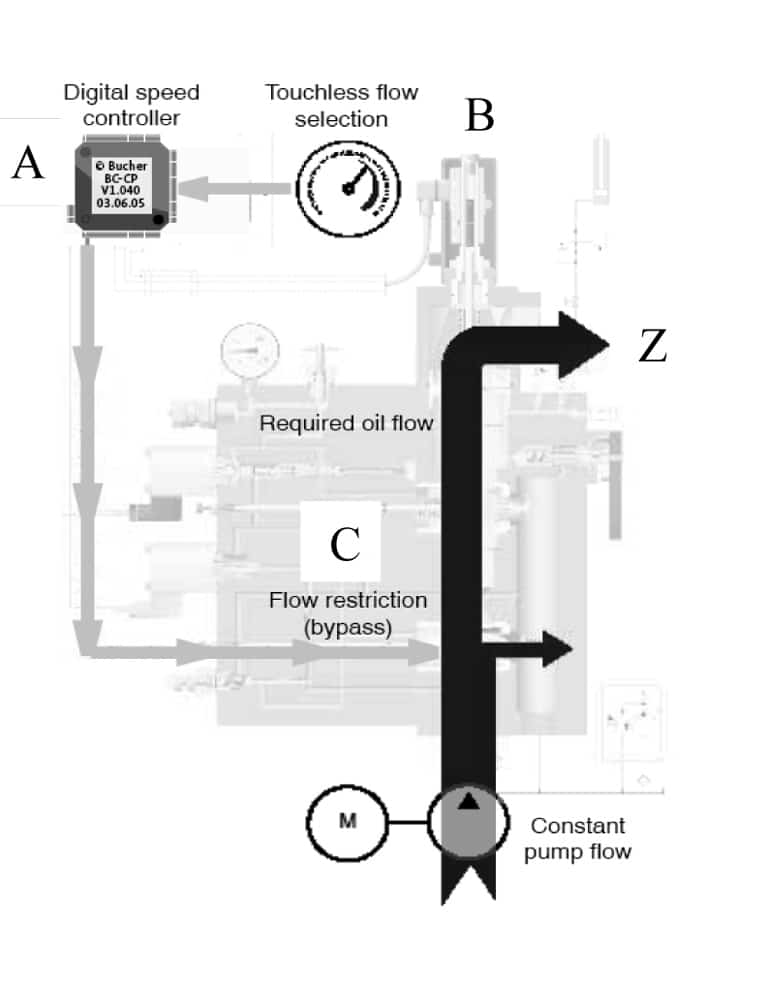
Figure 3 shows in a simplified overview the working principle of Bucher Hydraulics’ electronically controlled lift valve LRV during an UP-ride.
The most relevant components:
- A Sophisticated digital electronics tocalculate a smooth ride curve under all conditions
- B Contactless feedback device of the current oil flow rate. Due to the contactless “Hallprinciple”,it works maintenance free throughoutthe entire lifetime
- C Proportional valve which controls thebypass oil flow, which finally results in thecorrect flow rate provided to the cylinder (Z)
All the effort in the design has one main goal: unsurpassed ride comfort independent on load and temperature. In addition, the efficiency of the drive is already remarkably higher compared to conventional mechanical valve blocks. Depending on the application, up to 30% less energy consumption compared to mechanical designs is the result of the electronically controlled valve technology. This results of course in 30% less heat, which is highly appreciated by all interested parties. As a final benefit, a lot of applications do not require an oil cooler, as was previously the case when running with conventional mechanical valve blocks.
Figure 4 shows in an impressive comparison the high accuracy and ride performance of the electronically controlled valve technology compared to a mechanical valve.
IMPORTANT: On the x-axis the motor run time is shown. This means, the covered distance for one ride is the same, but obviously the run time may vary drastically when using a mechanical valve.
This results in a huge advantage for the electronically controlled valve. Up to 30% energy saving, by just using this sophisticated technology should be reason enough. Not to mention further money saving facts, such as less downtime due to changing running conditions (e.g. changing ambient temperature or payload). This prevents unscheduled service interventions which would be necessary on mechanical valves, to adapt the mechanical adjustments to these new conditions.
The graphs shows clearly the energy savings potential of up to 30%, by just being accurate and “on time” in the top floor. This is ensured with the fact that the ride curve is always the same, no matter whether you run with full or empty cabin or with hot or cold oil. Hence, you just run the installation with the factory preset parameters and the installer may set the timing for the deceleration signals at its preferred timing sequences.
There will be no deviation due to changing operating conditions!
- always the same start point
- always the same creep speed distance
- always the same acceleration/deceleration slope
- always the same speed
- always a smooth ride without jerking
And last but not least, as already mentioned, in many cases there is no need for an oil cooler due to the energy savings of up to 30%.
3.2 Frequency controlled hydraulic drives
By using a frequency inverter to control the speed of the hydraulic pump, the efficiency of the hydraulic drive increases remarkably. As a result, the thermal loss gets further reduced compared to the good values of the electronically controlled valve.
The oil flow gets mainly controlled in both directions (UP and DOWN) by the pump speed, which is determined by the individual speed of the attached motor. The body of the valve consists again of the crucial elements of the electronically controlled technique. A smooth speed control is only feasible in combination with the working principle of the electronic LRV valve, already explained on the previous chapter.
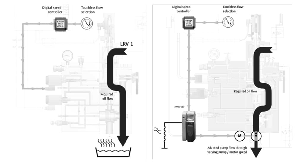
Figure 5 shows in an impressive manner, that the heat loss can be dramatically reduced by using inverter techniques (right hand sketch). A next important advantage; the small amount of remaining heat dissipation can be forwarded by a small cable from the inverter to a brake resistor – far less expensive than a hosing/piping with required cut outs in the building structure to connect a conventional oil cooler…to further reduce motor room heating the breaking resistors can be mounted inside the lift shaft.
For increased traffic demands, do not add a cooler, use hydraulic inverter technology! Beside the more efficient drive, you will appreciate further benefits:
- less noise emissions
- no delays when the ride starts
- no current peaks when motor starts
4 BEST PRACTISE: SOLUTIONS FOR ENERGY EFFICIENT MODERNISATION
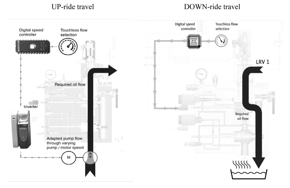
The latest product development from Bucher Hydraulics combines the frequency controlled UP-ride travel and the electronically controlled DOWN-ride travel with the benefits of both solutions which where explained in details in the previous chapters. This solution will cover the gap between the electronically controlled lift valve and the full frequency controlled hydraulic drive.
4.1 Compact VF power unit
The main applications for this product are installations with low usage intensity such as residential buildings with up to 6 levels, where energy efficiency is in focus and the best price-performance is requested. Most of the worldwide installed lifts belong to the usage category 1 (according VDI 4707) with an average travel time up to 0.3 h/day which is related to approx. 200 travels per day.
Up-ride travel:
The frequency controlled power unit will help to reduce the energy consumption during the UP-ride travel because of the effective speed control of the motor-pump combination during the acceleration and deceleration of the riding curve. In addition, the application with a frequency inverter can limit the current by reducing the speed for higher cabin load. Especially beneficial for modernisation, where highest cabin load with limited power connection can be covered.
For lifts with low usage intensity the frequency inverter has a certain disadvantage because of its standby consumption. On the other hand there are efforts of the different manufacturers of the frequency inverters to reduce the energy consumption in standby mode to reduce the negative impact.
Down-ride travel:
The DOWN-ride travel will be operating as with the electronically controlled valve LRV-1.. The closed loop control of the oil flow with the LRV-1 allows a comfortable and reproducible levelling accuracy of +/- 3mm. According to the new EN81-2/A3 it will become mandatory to stop within +/- 10mm among all different temperature and load conditions, which would be hard to achieve with a mechanical valve.
Compared to the known Bucher Hydraulics frequency controlled power unit, the Compact VF will not transfer the heat dissipation through the break resistor to the air, but transfer into the oil. For that reason this solution will be preferred for low travel demand. The big advantage is the saving of extra costs because the frequency controller needs no break resistor functionality nor an encoder to detect the motor speed. With this reduced complexity the installation will be fast and easy.
Figure 6 shows in an impressive manner, that energy loss can be dramatically reduced by using inverter techniques only in UP-ride travel. This leads in reduction in energy travel demand up to 40% compared to a mechanical valve.
4.2 Step by step modernisation with Multikit
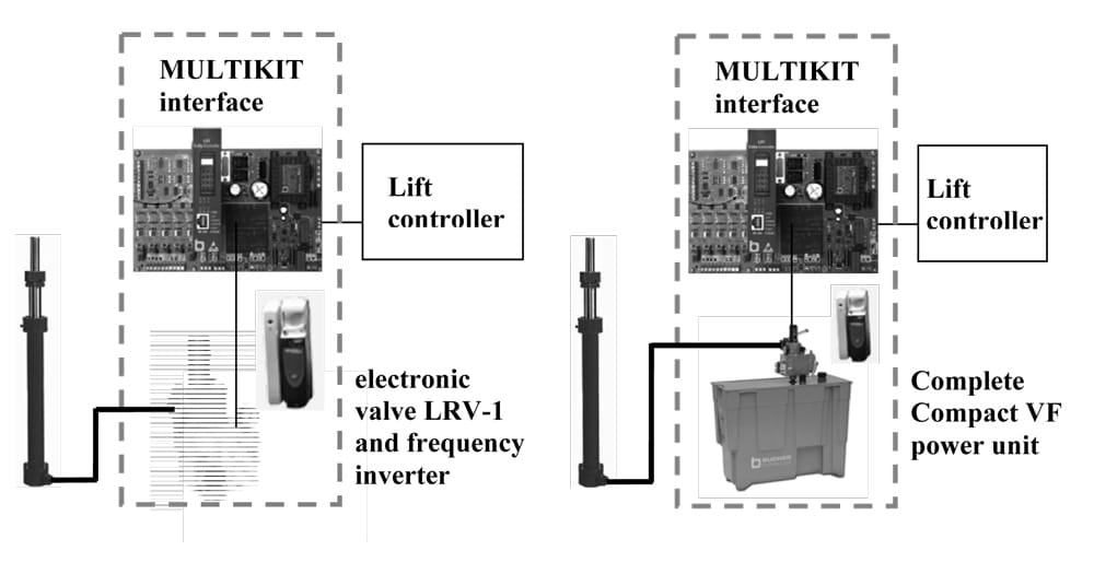
In a time, where many new installations are delayed and new code requirements are requested, it is essential to consider modernisation solutions. For many lift owner an expensive maintenance, wasteful energy consumption and poor ride comfort is an issue. To modernise such kind of installations, Bucher Hydraulics has developed a step by step modernisation kit to link the lift controller with the hydraulic power unit. With the Multikit, the power unit can be upgraded to the latest drive technology within a very short time with an optimal price performance ratio.
The modernisation kit includes the electronic interface board with wide range inputs for electrical signals from 12V to 230V AC or DC. This allows to keep the existing lift controller and therefore to minimize replacement-time and -cost. In addition, the modernisation kit includes all mechanical components and electrical cabling for installation as well as detailed documentation for easy commissioning.
Figure 7 shows the result of a modernisation, where an existing valve has been replaced with an electronically controlled valve and a frequency inverter to result in a Compact VF solution. Alternative the complete power unit can be replaced , weather it’s a Compact VF or one of the other Bucher standard power units such as Compact, Comfort or Economy Line.
5 CONCLUSION
The analysis of the lift marked has shown that more than 1.2 million hydraulic lifts in Europe are older than 20 years and there lays a great potential for substantial reduction of energy consumption via modernisation. This fact is also in line with the targets of the European Commission to reduce energy consumption by 20% by the year 2020.
Bucher Hydraulics developed therefore the “Compact VF” with the possibility to reduce travel demand by up to 40%. With this cost optimised solution an unrivalled price performance ratio can be achieved. To give the lift owners a possibility to spread modernisation costs over several years the “Multikit” allows therefore a step by step modernisation also in combination with the Compact VF technology to reduce energy consumption substantial.

6 REFERENCES
De Almeida, A., (2010). E4-Energy Efficient Elevators and Escalators, Report for Intelligent Energy Europe, Brussels
Verein Deutscher Ingenieure, (2009). VDI 4707 part 1 Lifts Energy efficiency, Guideline, Düsseldorf
Chartron, M., (2009) Interest is rising for energy efficiency in lifts, News letter ELA European lift association, Brussels
Bucher Hydraulics, (2010) Product descriptions: LRV, VF-LRV, Multikit, technical documentation, Neuheim Switzerland
Get more of Elevator World. Sign up for our free e-newsletter.