Escalator Overspeed and Anti-Reverse Protection Meter
Dec 1, 2012

A new utility model applicable to various escalators is examined.
Ning Li, Yihui Ruan, Yuandong Jiang, Xueming Chen, Rongfeng Lu, Bin Huang, Zhe Cheng and Mingtao Chen
A new testing system, which can make use of advanced microcontrollers in order to test elevator overspeed and anti-reverse protection, is examined in this article. This utility model is characterized by simple structure, small volume, high response speed, low energy consumption and high reliability, all of which improve safety. The utility model is applicable to various escalators that use speed sensors.
Escalator accidents have frequently occurred over the past several years. A 13-year-old boy was killed and 30 others injured when a crowded ascending escalator suddenly reversed direction at a subway station in Beijing on July 5, 2011. According to the press, the escalator was fully loaded with passengers when it apparently lost driving momentum while the brake appeared to be simultaneously not functioning. Due to gravity, the full load of passengers caused the escalator to roll back. The passengers lost balance and fell upon one another. This incident has increased public concern for escalator safety.
Escalator designs must enable a unit to stop when it unintentionally reverses or its rated speed is more than 120%. The meter discussed in this article can inspect the overspeed and anti-reverse protection function of escalators. This new type of speed-supervision meter is a digital instrument designed for the measurement of escalator overspeed and anti-reverse protection. This speed-measurement equipment adopts a speed sensor. Some escalators are fixed near the flywheel, while most are fixed near the driving chain sprocket. The system is composed of software and hardware in light of its working mode. The hardware component of the system includes a microcontroller, key, display screen detecting port, etc. The eight-bit microcontroller uses the “C” programming language.
The Principle of Measurement
In this article, the escalator’s drive unit is called a “first sprocket.” The drive unit is located in the upper truss extension and may be fitted with the overspeed and anti-reverse protection device. The main drive shaft has two sprockets at each end of the axle to drive the step chains. The sprocket at the end of the axle, directly connected to the drive chain is referred to as a “second sprocket.”
The core of an escalator is a pair of step chains looped around two sprockets (Figure 1). A motor provides the driving force, but it does not directly act on the sprocket. A main drive chain acts as the connection link between the sprocket and the motor. Motor rotation speed is t (rpm), namely t/60 (rps). The rated speed of the escalator is v (mps). The number of second sprocket teeth is r1, the number of the first sprocket teeth is r2. The reduction ration for the reducer is i. The number of pulse in one rotation of the flywheel or sprocket is n. The ratio between the first and second sprockets is r1/r2. The total reduction ration between the second sprocket and motor is q, and q = i r1/r2.
Pulse frequency f is tn/60q (Hz), meaning the number of pulses per second. The pulses are generated by the speed sensor when the escalator runs at rated speed. If a pulse is generated, the moving distance of the escalator is v(tn/60q); namely, 1 = 60v/tn(m/pulse). If the speed sensor is put near the flywheel, q is 1.
The following example illustrates velocity-measurement principle. For instance, Canny Elevator supplied Suzhou subway station No. 1 Line with 199 escalators. Figure 2 shows 12 holes in the flywheel of the escalators.
If motor rotation speed is 970 rpm, namely 12.2 rps, pulse frequency f = 16.2 X 12 = 194 Hz. If pulse is generated and the rated speed of the escalator is 0.65 mps, the moving distance of the escalator is 0.65/194 m, or 3.35 mm per pulse. If reversal distance of the escalator is 100 mm, the number of pulses the speed sensor generate is 45.
Fixed at the bottom of the brake, the speed sensor is used to monitor the flywheel speed, as well as to avoid reversal and will stop the escalator in case rated speed is over 120% or under 80%.
In this example, 45 X 120% = 54; 45 X 80% = 36. If reversal distance of the escalator is 100 mm, and the number of pulses the speed sensor generates reaches 54 or 36, the escalator should be stopped; otherwise, it does not meet the demand. If the first sprocket is fitted with the speed sensor, q is i. If the second sprocket is fitted with the speed sensor, q is 1 r1/r2i.
Hardware Composition
Figure 3 illustrates the hardware composition of this meter. The core of the hardware part is the microcontroller (model 89E564RD2). The microcontroller is embedded to implement the intelligent control algorithm. The device relates to a key-input processing circuit for processing key input data from a key-matrix circuit and for transmitting the processed data to the microcomputer, and the key-output processing circuit can be transmitted to the controller. The output signal, which is generated by the microcomputer, is sent to the main circuit board of the escalator. This analog impulse signal is generated by the speed sensor. The liquid-crystal display (LCD) displays the character corresponding to the data received on its input data port from the microcomputer.
Figure 4 shows the front panel of the instrument. The advanced microcontroller system and large chromatic LCD not only make the operation more convenient, but also have a friendly human/machine interface. The model features a bright-red, .43-in.-high LED with floating decimal. The instrument displays “1.” for “over range.”
When the meter is on, pressing and releasing the “MODE” button will cause switching among rated speed, motor rotational speed, reduction and the number of pulses of one flywheel or sprocket circuit, and the screen will display the initial value. Pressing the “±” button will increase or decrease the initial value by 1. Pressing and releasing “ENTER” will confirm the current value. The “EXIT” button is used to exit the current mode. Pressing the “ON/OFF” button will turn the meter on or off.
Software Design
The microcontroller features a data-processing function. Elevator inspectors can set up parameters through microcontroller programming, such as escalator rated speed, motor rotational speed, reduction ratio and so on. The system can simulate pulse signals generated by the speed sensor. The signals will be transmitted to the control circuit board. The control software will be implemented in the programming environment of µ Vision4. A software flowchart is shown in Figure 5.
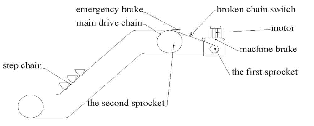
Figure 1: Structure and safety devices of a typical escalator 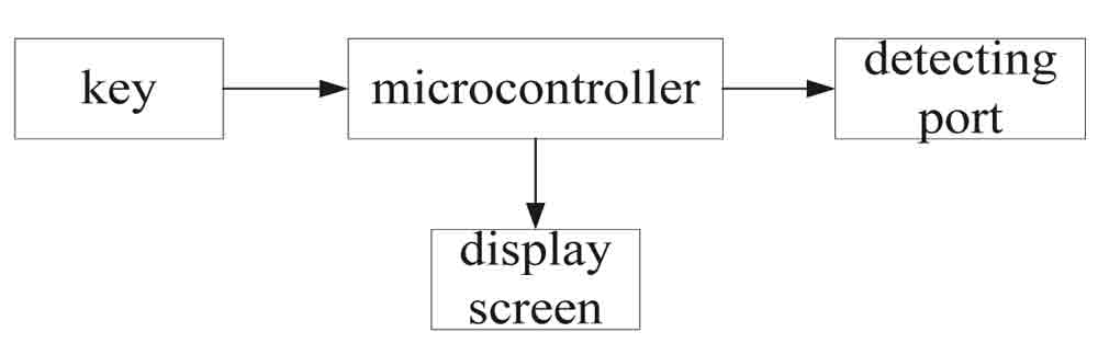
Figure 3: Hardware composition control circuit board 
Figure 4: Front panel 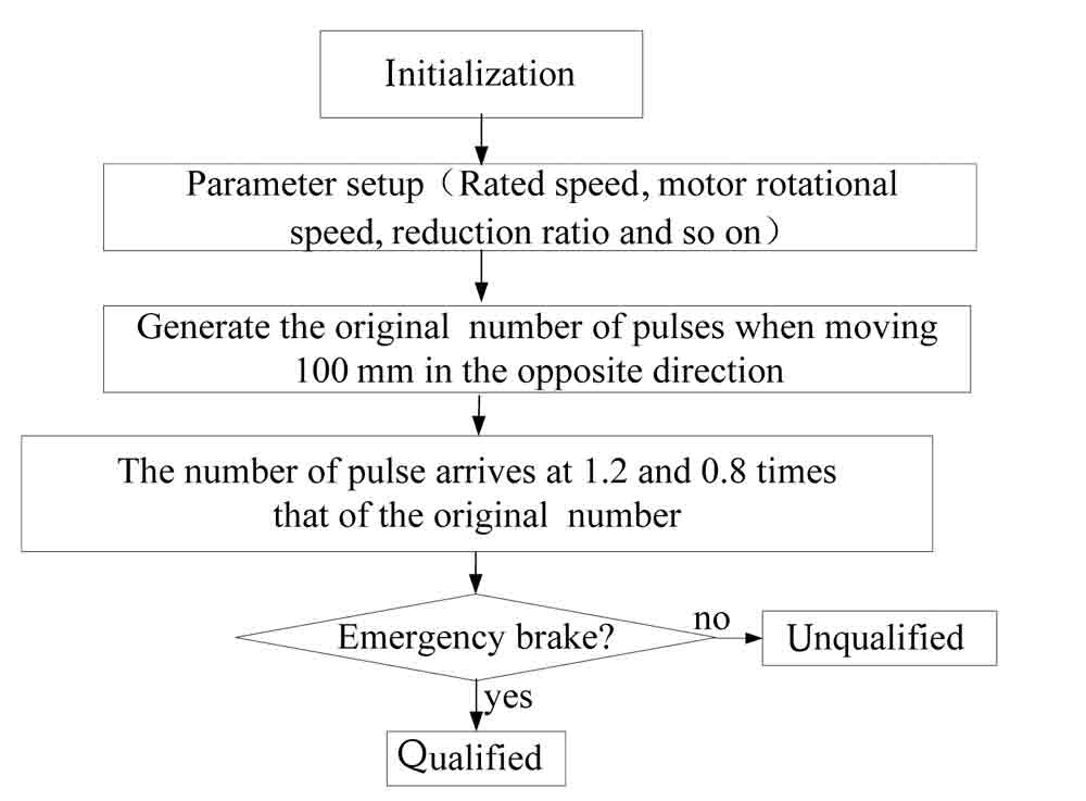
Figure 5: Software flowchart
Get more of Elevator World. Sign up for our free e-newsletter.


