Evaluation of the Escalator Truss Subjected to Forced Displacement for Seismic Design
Nov 1, 2017
An accurate method of analysis for seismic design is detailed.
by Kentaro Sekiguchi, Noritaka Horie and Hirobumi Utsunomiya
This paper was presented at  Madrid 2016, the International Congress on Vertical Transportation Technologies, and first published in IAEE book Elevator Technology 21, edited by A. Lustig. It is a reprint with permission from the International Association of Elevator Engineers
  (website: www.elevcon.com).
A serious earthquake occurred in Japan on March 11, 2011, and escalators collapsed. This was caused by the interlamellar displacement of the building (called “story drift”), which resulted in fluctuation of the escalator’s span. The forced displacement imposed on the escalator truss might have caused it to sustain substantial damage. Therefore, Hitachi evaluated its strength under forced displacement using simulation. Furthermore, the simulation was performed based on the actual size. According to the simulation results, even in the case of forced displacement of 200 mm, the escalator truss did not collapse. In addition, we have established the means of strength analysis of the escalator truss for seismic design.
Introduction
Japan has had an increased frequency of earthquake occurrences. The seismic criterion for escalators in Japan was introduced after the South Hyogo Earthquake (Mj7.2, January 1995) and was standardized in the Lift Technological Standard Commentary (Version 2009).[1]
However, the phenomenon of collapsing escalators[2] still occurred during the Great East Japan Earthquake (Mj9.0, March 2011). It was suspected that the cause of the escalator collapsing was due to story drift of the buildings. As a result, the seismic design criteria of the escalator, which was the industry’s standard, was enforced by the Building Standards Act in 2014.[3] When the story drift is larger than the clearance, the escalator frame experiences a compression due to the forced displacement of the structural beam. The influence that the compression has on the escalator frame is not known. When the clearance is small, it is necessary to prove that the deformation of the escalator frame does not compromise its safety.
This article explains the way of thinking of the construction of the Hitachi escalators after the adaptation to the new seismic design criteria. Furthermore, it describes the evaluation of the forced displacement on the escalator truss due to the shortage of clearance. The purpose is to comply with the seismic criterion through the local remodeling of the installed escalators.
Background and Objective of Development
Japanese Seismic Design Criteria
The frame of an escalator comprises the truss and its support angles at both its ends. The escalator is suspended across the structural beam at the top and bottom stories by the respective support angles. When an interlamellar displacement of the building occurs, the span of the installed escalator fluctuates. The slender aspect ratio of the building affects the change in the span of the escalator.
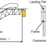
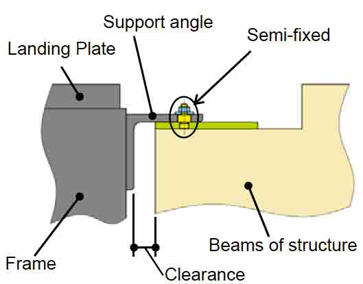
Figure 1 shows the side view of a typical escalator and an enlarged view of the support angle. The span (K) fluctuates from its initial dimension (K0) by story drift. The clearance (the distance between the support angle and the structural beam’s vertical plane) and overlap length (The overarching length of the support angle over the structural beam in the horizontal plane) of the support angle are changed during an earthquake.
The seismic design criteria enforced by the Building Standards Act states that the size of the story deformation angle must be 1/24th of the escalator’s height. This is more than four times the story deformation angle of 1/100th, which was once the conventional industry standard.
When the value of the story drift (γH) is larger than the clearance, the escalator frame experiences compression due to the forced displacement of the structural beam.
Corresponding Structure of New Escalators
Hitachi has considered both the overlap length and clearance in response to the change in story drift in the new seismic criteria. In the case of a one-side-fixed structure, where one side is fixed, while the other side is not, it is only possible to provide sufficient clearance at the side that is not fixed. Furthermore, if the clearance becomes large at one side, the moment arm of the support angle increases, causing the stress condition to become severe. On the other hand, necessary clearances can be allocated at both ends of an unfixed structure. In this case, the clearance at both ends is shortened, thereby causing the stress that occurs at the support angle to be reduced. Therefore, the unfixed structure at both ends was adopted for new escalators. The lateral motion of the escalator is constrained by utilizing parallel restrictors (lateral direction safety catch).
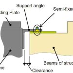
When considering the shaking of the building caused by earthquakes that are not huge, one side of the support is to be semi fixed.[4] The semi-fixed support angle is constructed for an earthquake that is not huge and is a structure that becomes unfixed before substantial damage develops within the frame during a major earthquake. This acts as a “fuse” for earthquakes. (Figure 2 shows a side view of the semi-fixed side.)
The semi-fixed end is created by adding parts such as a semi-fixed pin to an unfixed end. Using this innovation, Hitachi aims to increase the product sales of human-friendly escalators and lifts.[5]
Issues With Installed Escalators
New escalators and existing escalators are subjected to seismic damage when an earthquake occurs. The installed escalators are expected to be able to comply with the latest seismic design criteria after seismic-resistance remodeling is applied. When this is realized, the installed escalator can attain the safety level equal to that of a new escalator.
For escalators currently in operation, their extreme lengths must be shortened to increase the clearance in order to prevent compression during earthquakes. However, the replacement of such an escalator in its installed location might be difficult, thereby inhibiting any form of seismic-resistant remodeling. Therefore, strength analysis must be done for escalators that are already in operation.
This article describes the elevator strength analysis, which uses elastoplastic analysis to obtain results similar to those generated by the actual-size test the Building Standards Act had conducted.
The deformed state and residual strength of the frame when it experiences a forced displacement by a structural beam has also been determined.
An actual-size test was conducted by the Building Standards Act in which a forced displacement of 200 mm was applied to a frame with a 3-m rise.[6] The horizontal reaction force displacement curve produced by the analysis is compared with the above-mentioned test’s results, and the method of analysis is elaborated in the following section.
Strength Analysis
Test Conditions
The forced displacement applied to the escalator was 200 mm, the same as the testing machine’s stroke used in the actual-size test. In the case of a 3-m rise, the maximum compression value based on 1/24 of the story deformation angle in the seismic criteria is only 125 mm. However, a 200-mm forced displacement was used in the simulation analysis to replicate the conditions of the actual-size test for comparison purposes.
Model Shape
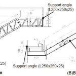
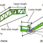
Two types of frames were considered. The first is a truss frame (pattern A), while the second is a frame where H-rolled steel materials are extruded to form a beam (pattern B). For comparison with the actual-size test, the rise of the escalator is set at 3 m (same as the actual-size test). The outer dimensions of each frame are shown in Figure 3. In addition, another simulation was conducted on an escalator with a frame of 5-m rise to check the influence of the 200-mm forced displacement on an escalator with a higher rise.
Simulation Analysis Conditions
The escalator was modeled using a frame and support angle necessary for withstanding its weight. The analysis model was created using primary element shells, which contain integral calculus elements, and a concentrated point mass was given to each element. The mass of every passenger, step, moving handrail, balustrade part and the internal apparatus was input as a vertical point load. The loads were applied onto the stringer at the upper portion of the frame structure.
For the boundary conditions, the upper support angle was fixed, whereas the lower support angle was given a horizontal forced displacement. The lower support angle rested on a rigid wall, which simulated a structural beam. This rigid wall touched both the horizontal and vertical surface of the support angle and gave the frame a forced displacement as the rigid wall was displaced horizontally.
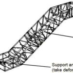
Figure 4 shows the conditions of the frames after the forced displacement had been applied. The simulation results indicated a displacement difference of 5 mm between the beams of the structure. Since it is not likely that the beam will be compressed uniformly, this displacement difference was regarded as acceptable.
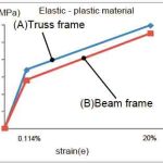
In the simulation, a compression displacement of up to 200 mm was applied. The live load and apparatus weight were introduced at 0-0.15 s. as an initial condition, while the forced displacement was introduced at 0.15-0.5 s. The whole model was simplified, and the elastic-plastic properties of the material were approximated using two straight lines (Figure 5).
For accurate comparison with the actual-size test, the following material properties were given to the respective frames: truss frame shape A = fracture stress of 598 MPa; beam structure shape B = fracture stress of 555 MPa. The analysis solver used was LS/DYNA (by Livermore Software Technology Corp.).
Simulation Results
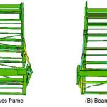
Figure 6 shows the side view of the frame deformation when a forced displacement of 200 mm was applied to both frames, while Figure 7 shows the front elevation. The deformation of the frame was more severe at the lower section than at the upper section. The flexural point was located at the lower length of the frame; as the deformation increased, so did the flexural angle.
Comparing the deformation from the front elevation, truss frame A experienced a larger change than beam structure frame B. This is likely due to the difference in rigidity of the respective frames’ constituent members.
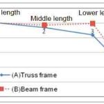
Figure 8 shows the change in dimension for four sections, namely:
- Upper horizontal section
- Middle gradient
- Lower horizontal section
- Distance between support angles.
It is the comparison between the initial state and deformed state. The deformation of truss frame A at the lower horizontal section was larger, while the increase in flexural angle of beam frame B was greater. Thus, the above-mentioned tendency was confirmed.
The stress around the lower flexural point was obtained through the analysis. These values were below the fracture stress of the material. For truss frame A, the stress value obtained was 536 MPa (fracture stress safety factor of 1.11). The stress value obtained for beam structure frame B was 368 MPa (fracture stress safety factor of 1.50).
Comparison Between Strength Analysis and Actual-Size Test
Figures 9 and 10 show the relationship between the horizontal force in the longitudinal direction and the forced displacement applied to truss frame A and beam structure frame B. The data of the actual-size test is depicted as a broken line. The thin continuous line reflects the analysis results of a 3-m rise, while the bold continuous line reflects the analysis results of a 5-m rise. As seen from Figures 9 and 10, the graphical representation of the simulation analysis resembled the results of the actual-size test. The results obtained through the strength analysis and the actual-size tests were similar in shape.
When comparing the strength-analysis results of the 3- and 5-m rises, effect of the change in rise was not great. Overall, for both the simulation and the actual-size test, the horizontal reaction force still existed, even up to the point where the forced displacement was 200 mm.
It was confirmed that a frame does not collapse by a forced displacement. If horizontal reaction force obtained from the analysis decreases to zero, it would mean that the escalator frame can no longer be supported and thus imply that the escalator will collapse under a forced displacement of 200 mm. Since the simulation results indicate that the horizontal force did not reduce to zero, it is confirmed that the frame did not fall off by the forced displacement. Therefore, Hitachi can evaluate by the simulation.
On the other hand, no breakage of any structural member or weld within the frame was detected during the actual-size examination. Moreover, during the simulation analysis, the stresses found in the material of frame A and frame B under the forced displacement did not reach the yield strength of the material. Therefore, it can be concluded that when forced displacement is applied to the escalator frame, the analysis shows that the escalator will not collapse.
Conclusion
This article describes the way of thinking that Hitachi uses regarding the new escalator design created to adapt to new Japanese seismic criteria. For the case of installed escalators, strength analysis was conducted on the frame, and the information obtained is summarized as follows.
During both the actual-size test and the simulation analysis, the forced displacement caused a plastic deformation onto the frame, but the horizontal reaction force acting on the frame remained, thus confirming that the escalator can still be supported. For forced displacements larger than 200 mm, more simulations have to be done to determine if the escalator frame will collapse. The actual-size test showed no evidence of failure of the escalator’s members, while the simulation analysis also indicated no sign of material failure. Thus, it is concluded that the outcome of the actual-size test can be predicted by using this method of analysis. Therefore, when an escalator truss is subjected to forced displacement, this described method of analysis for seismic design is accurate in proving that the escalator will not collapse.
- Figure 1: Escalator system
- Figure 2: Side view of the semi-fixed side
- Figure 3: Side view of the escalator frames
- Figure 4: Model of the analysis
- Figure 5: Material property (SS400)
- Figure 6: Side view of the frames (analysis)
- Figure 7: Perspective illustration of the frames (simulation)
- Figure 8: Change in length
- Figure 9: Displacement-force curve of truss frame A
- Figure 10: Displacement-force curve of beam frame B
References
[1] The Japan Building Equipment and Elevator Center Foundation, Japan Elevator Association. “Commentary 2009 Version of the Lift Technology Standard,” p.167-182 (2009).
[2] Ministry of Land, Infrastructure, Transport and Tourism. “Reference About the Opinion Offer About ‘the Preventive Measures Against Drops Tentative Plan of the Escalator’”(2012).
[3] The Japan Building Equipment and Elevator Center Foundation, Japan Elevator Association. “Commentary 2014 Version of the Lift Technology Standard,” p.1.3.115-1.3.126 (2014).
[4] Horie, N., Sekiguchi, K., and Utsunomiya, H. “Strength Analysis of the Truss in Semi-Fixed Structure,” Japan Society of Mechanical Engineers 2014 annual meeting (2014).
[5] Fukuda, T., Sakaue, M., and Ise, Y. “Escalators That are Friendly to Humans and the Environment,” ELEVCON, The 21st International Congress on Vertical Transportation Technologies (2010).
[6] Tokyo Denki University. “Report of 2014 Building Standards Act Maintenance Promotion Business, Investigation number: P8, Terms of reference: Examination About the Way of the Measure for Safety of the Escalator” (2014).
Get more of Elevator World. Sign up for our free e-newsletter.
