Five Steps for a Smooth Elevator Startup
Aug 1, 2024

A guide to troubleshooting issues
submitted by KEB America
There are a few ways to perform an elevator startup. However, the method described in this article is helpful for troubleshooting any issues during the startup process. Our preferred startup method involves starting with the motor unroped or hung.
This method allows the motor to spin freely after the motor and encoder learn. By doing so, it can be confirmed that the motor spins normally, the encoder functions correctly and the drive functions as expected. If an error occurs after the ropes are put on the car, it can be determined that incorrect learns, incorrect data and other scenarios are not causing the issue because the motor has spun without the ropes.
Induction and permanent magnet (PM) motors require slightly different startup procedures. For an induction motor, it is necessary to verify the motor data, perform a motor learn and set up the encoder. On the other hand, PM motors require verifying the motor data and performing both a motor learn and an encoder learn.
Step 1: Verify Data
How would a startup work on an unroped or hung car?
Check the motor data. It is crucial that the motor data matches the motor nameplate because it will affect the internal motor model calculated by the drive and the encoder position for PM motors.
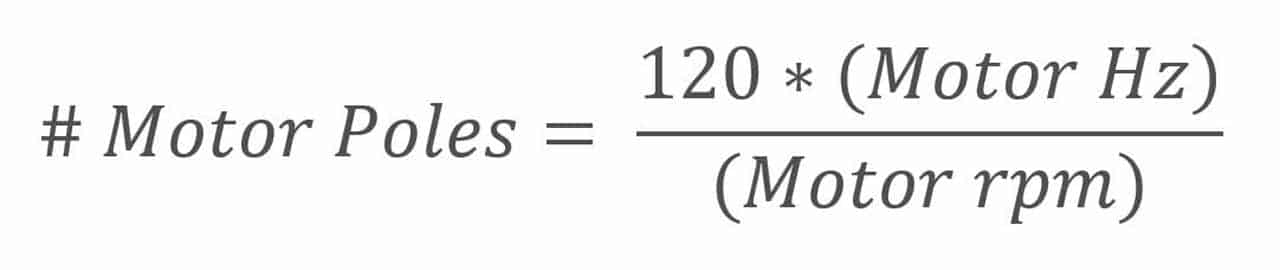
Equation 1: Motor Pole Equation
Equation 1 provides the method for calculating the number of poles in a motor. The motor poles should be an even whole number. Motor manufacturers have the ability to adjust the rated motor data to suit specific applications. A general guideline is that a difference smaller than 0.25 is considered close and should work, but ideally, the number of poles should be as close as possible to an even whole number.
For specific parameters to check, refer to the details below:
Encoder Data
- LE02 – Encoder PPR
- LE05 – Encoder Multiplier (2 for Induction Motors and 8 for PM Motors)
Basic Setup
- LN01 – Sheave Diameter
- LN02 – Gear Reduction Ratio (This should be 1 if a gearless motor)
- LN03 – Roping Ratio
Machine Data
- LN01 – Sheave Diameter
- LN02 – Gear Reduction Ratio (This should be 1 if a gearless motor)
- LN03 – Roping Ratio
Speed Profile
- LS01 – Leveling Speed
- LS02 – High Speed
- LS03 – Inspection Speed
- LS04 – Correction Speed
- LS05 – Intermediate Speed 1
- LS06 – Intermediate Speed 2
- LS07 – Intermediate Speed 3
Note: Depending on if the controller creates the S-curve, also known as speed curve, or if the drive does, this will affect which parameters are needed. If the control type in US04 is Serial Speed or Analog Speed, then only LS02 – High Speed needs to be adjusted.
The data should match the machine and elevator specifications. Although the controller OEM might put the motor data into the drive before installation, double check to make sure that the data still holds true from when the site survey was done.
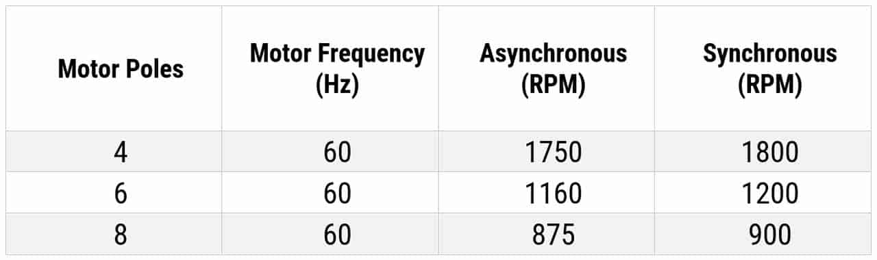
Induction motor data should always reflect 60Hz, asynchronous rpm data. Induction motors are asynchronous, meaning that there is loss of speed inherent in the system due to slip. Slip is inherent in induction motors due to the relationship between the stator and rotor. The rotor field will lag the stator field, which will create torque to move the motor.
When calculating motor poles for an induction motor using slip speed, you will never get an even whole number. For more information, refer to LM02 – Motor RPM in the F5 drive manual. You can also consult Table 1 for 60Hz data.
PM motors are synchronous motors, which means there is no speed/slip loss in the system. Therefore, the rated or application motor data should be entered as is. The motor data should provide an even whole number of poles.
Step 2: Motor Learn
The motor learn is important to create an equivalent circuit motor model for optimized performance. The motor sigma inductance, stator resistance and magnetizing current are calculated from the motor learn based on the entered motor data and the learn procedure. If the learned values are incorrect, then this can lead to poor current control. Therefore, it is critical to verify that the motor data is correct. Performing a learn with incorrect motor data may result in poor motor control, leading to high current and/or ride quality issues such as vibration.
To perform the motor learn, the inspection speed must be changed to zero and the brake disabled. The inspection speed or speed profile can either be a controller or a drive setting depending on the speed control type.
To begin the motor learn process, press and hold the inspection switch. The drive screen will change, showing “calculating motor data” and displaying different frequencies that the drive is outputting. You should also hear the motor beginning to hum. The learning process can take anywhere between 1 to 5 min, depending on the motor. Keep holding the inspection command until the drive screen indicates that the test is done. The drive will then automatically create and save the motor model.
After the motor learn process, the drive will update some parameters in the motor data. The motor inductance, motor resistance, and for PM motors, the motor voltage will decrease to about 70%. PM motors need the encoder position to be learned in order to run properly.
Step 3: Encoder Learn/Set Up
The encoder learn is required for PM motors because the rotor is magnetized by permanent magnets, and the drive must modulate at the correct commutation angle to the motor to generate maximum torque. The rotor’s position is determined by the encoder learn. If the position is incorrect, high current, a drifting car and/or slight to no movement of the motor can occur.
There are two methods for determining the encoder position for PM motors, the Stationary Pole Learn (SPI) or the Encoder Pole Learn (P Learn). Both methods will calculate the correct encoder position, but the P Learn will also determine the correct A/B encoder phasing. The P Learn requires sheave movement.
For an unroped or hung car, it is recommended to perform the P Learn. Inspection speed or speed profile must be set to 0, the brake must be able to pick, and there must be no load or a balanced car for the motor to spin freely. The screen will say to either let go of inspection so the drive can change the encoder channels and hit inspection again or the test is complete. Once completed the motor should be able to run.
The second type of encoder learn procedure is the SPI. Sheave movement is not required, and this requires that the inspection speed or speed profile be set to zero and the brake be disabled. This procedure will only find the encoder position; therefore, the correct encoder A/B phasing should be changed manually.
Step 4: Spinning the Motor (Unroped/Hung)
After finishing the required learn(s) for the motor, the next step is attempting to spin the sheave. Table 2 shows speed control gain values in the KEB F5 that may need to be adjusted for an unroped/hung car.
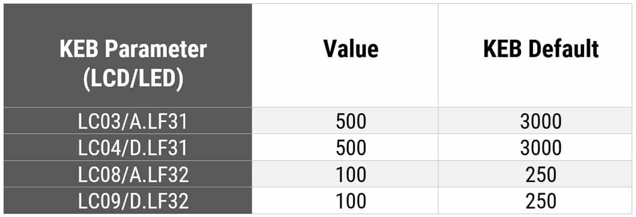
The speed control gains might need to be adjusted lower because the default values are meant for a motor that is under load. Typically, if the gains are too high the drive can fault out with Speed Following Error at the beginning of the run due to over response within the speed control loop or the motor can vibrate significantly.
Step 5: Spinning the Motor (Roped)
Once the motor can spin freely without being roped or hung, the ropes can be installed on the car and the speed control gains set back to default. The car can be operated up and down the hoistway for inspection.
If the motor struggles to run, rule out issues with the drive, the encoder, or any motor issues, as the motor has already spun freely. This problem typically relates to the mechanical side of the elevator system, or the drive may be limited by torque. Adjust LC30/0LF36, which is the maximum torque on the drive, to allow the drive to output more torque to the motor. LC30 is a percentage and is typically set to 250-300%, while 0LF36 is a set torque value, which typically ranges from 2.5 to 3 times the rated motor torque in LF17. The maximum torque value can go up to 500%.
If adjusting the maximum torque value does not help the motor spin, verify that there is no mechanical binding and that nothing is preventing the motor from spinning. Check the counterweight by putting a balanced load in the car and verify the motor current on the Home Screen/LF93. The current should be about the same in both directions. If not, the counterbalance is incorrect and must be adjusted.
The motor should be able to spin at or below the rated motor current. If an error appears after the ropes are installed, the issue has been isolated to after the load was put on the motor. This approach will make it easier to determine why an error appeared on the drive when the car is roped, saving time.
Get more of Elevator World. Sign up for our free e-newsletter.
![]()


![]()