Fred Hymans and the Theory of Rope Traction, Part One
Feb 1, 2017
The technical contributions of an industry legend are chronicled.
In no small measure will Frederick “Fred” Hymans’ influence and impact on the elevator industry relating to the mathematical theory of rope traction be chronicled. The first part of this two-part series will trace his technical contributions to the subject of rope traction, and the second will provide a small historical account about the man. Historians are invited to share any supplemental knowledge about Hymans.
The Euler Eytelwein Relationship
Before discussing his contributions, the concept of traction as a parameter should be properly attributed. The fundamental equation which related the ratio of the rope tensions at both the entering and exiting sides of the drive sheave to the available traction for any rope/sheave system is the classical Euler Eytelwein equation.[1] It is credited to Leonhard Euler (1707-1783) and Johann Albert Eytelwein (1764-1848), both scholars from an earlier time.
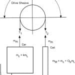
A simplified 1:1 roped elevator system is shown in Figure 1. The Notations used are defined toward the end of this article. SI dimensional units are shown.
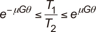
The Euler Eytelwein equation is valid where two ends of a rope having different rope tensions are wrapped around a sheave or similar object, such as a tree, pole or ship’s capstan. The equation covers rope pulls (tensions) in either direction. For rope slipping to not occur, the ratio of rope tensions must satisfy the general Euler Eytelwein relationship:
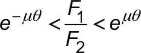
For elevators, Equation (1) can be rewritten to reflect the point of impending rope slip as:
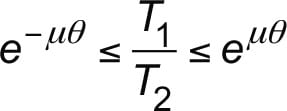
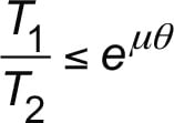
Reviewing this Euler Eytelwein equation shows that two conditions are presented. First, when the car masses are greater than the counterweight mass, T1 > T2 , and the middle and right terms of Equation (2) are used, so that:
Second, when the counterweight mass is greater than the car masses, , and the left and middle terms of Equation (2) are used:
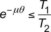
Equation (4) can be rewritten as:
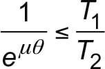
from which:
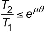
The mathematics bear out the obvious conclusion — namely, that the ratio of the heavy rope tension to the lighter one must not be greater than the available traction between the ropes and sheave grooves. The right sides of Equations 3 and 6 represent the available traction for a generalized rope and tractive surface on the sheave, which is expressed as:

The Koepe Friction Mine Hoist
Before discussing Hymans’ contribution to the theory of rope traction, mention of the contribution to the application side of traction drives by Friedrich Koepe, a German mining engineer, should be made. Koepe developed his friction hoist, which was popularized in the German mining industry. Up to that point in the 1870s, mine hoists were drum operated. In 1877, Koepe disclosed his concept for a friction drive in Germany Patent No. 218 (August 1, 1877)[2]; subsequently, in Austria (October 26, 1877); in Belgium (October 31, 1877); in France (November 2, 1877); in England (November 19, 1877); and in U.S. Patent No. 206,251 (July 23, 1878).[3] In reviewing the origins of traction-elevator development between 1877 and 1891, Dr. Lee Gray noted:
“The success of this elevator and the correlation between its operation and length of rise to the emerging elevator requirements of American skyscrapers would appear to indicate a fairly direct connection between this innovation and later developments in the U.S. However, while this claim is occasionally made, there is, in fact, no clear evidence that links Koepe’s elevator with the development of the traction elevator in the U.S.”[5]
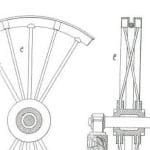
Koepe’s German patent embodied a large driving pulley arranged with a deep U-shaped metal channel in which the single hoist rope would contact a semi-round groove shape (Figure 3), taken from the German patent. In an alternate design disclosed in the U.S. patent, wooden blocks were assembled into the sheave rim to provide a wearable seat for the hoist rope. In the U.S. patent,[3] the text states: “The groove of the winding-pulley is, by preference, lined with wood or other suitable soft material for the purpose of increasing the friction and of diminishing the wear and tear of the rope.” Kempe’s Engineers Yearbook expanded on the different rope seats employed in Koepe friction hoists: “Wooden blocks are fastened in a recess in the rim of the wheel (sheave). In Germany, inserts of leather, rubber or bonded fibre are set in wooden blocks.” [4]
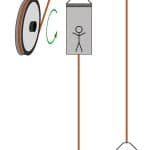
Koepe utilized the friction available in the groove to drive the double-car mine-hoist system but made no claim of developing sheave groove shapes that would optimize the available traction to meet the needs of an elevator system. It is notable that in the Koepe friction hoist, each car with approximately equal loading counterbalances the other (Figure 2).
While the worldwide timeline for inventions relating to friction (traction) schemes should be noted, Koepe’s friction hoist is notable. However, as Gray posited, there is no evidence to support the notion that Koepe’s friction hoist paved the way for subsequent elevator traction drive development.[5] In fact, Koepe’s invention only focused on one of the two variables comprising the exponent,
µθ, i.e., the angle of wrap, θ, in Equation (7), but not the coefficient of friction, µ. Subsequent development in the elevator industry focused both the coefficient of friction, µ, and the angle of wrap, θ, in equation (7).
Contributions by Frederick Hymans
At this point, one might ask, “Given the brilliant hypothesis expressed by the Euler Eytelwein equation, where does Hymans come in, and what’s his contribution to the subject of rope traction?” It begins with the notable points publicized in a presentation of an American Society of Mechanical Engineers (ASME) paper. In his presentation to the ASME Transportation Section in fall 1938, David L. Lindquist, Otis chief engineer from 1912 to 1944, traced the technical evolution of traction electric machines and drive-sheave grooves.[6] His presentation also chronicled the early use of various types of elevators dating from the 1850s, including the high-rise, high-speed roped hydraulic elevators. In addition to his commentary on control systems, safeties, governors, buffers, interlocks, etc., several sections of his presentation provide considerable context for discussion of the drive-sheave grooves for electric traction machines based on Hymans’ considerable R&D, as follows:
“As far as is known, the first attempt to apply an electric motor to an elevator was made in 1887 by William Baxter in Baltimore, and, in 1889, the first successful electric elevators were installed by Otis Brothers and Co. in the Demarest Building at Fifth Avenue and 33rd Street, New York City. These latter elevators were of the worm-gear drum type and remained in service for about 35 years.
“Many improvements were made to the drum-type electric elevator, but its speed was limited to about 400 feet per minute, and the travel was limited by the length of the winding drum, which could not exceed the width of the hoistway.
“Many attempts were made to improve the electric elevator for use in high buildings by eliminating the drum. Among the types used commercially were:
- Sprague-Pratt screw elevator of 1894, which used the multiplying sheaves and roping of the hydraulic elevator, but moved the crosshead by a screw driven by an electric motor
- Fraser elevator of 1899, which used two electric motors and a differential traction rope drive
- Van Buren gearless traction type elevator of 1903 with 2:1 roping
- In the same year, the Otis Elevator Co. developed the 1:1 gearless traction elevator, and the first one was installed in 1904 at the Duane Street Power Station of the New York Edison Co.
“The obvious advantages of the traction-drive principle demonstrated by the gearless traction elevator led to its application to the geared elevator machine as a substitute for the winding drum.
“In 1911, the first known attempt was made to use single-wrap roping in connection with geared machines, but sufficient traction could not be obtained with the conventional round groove, and, therefore, some form of pinching groove was necessary. The single-wrap roping was obviously a simplification.
“At first, a V-shaped pinching groove was used. This shape of groove gave ample traction when the sheave was new, but as the ropes wore the grooves, the pinching action and, correspondingly, the traction, became greatly reduced. It was practically impossible to determine by inspection how near at hand was the danger point of slipping so that timely provision could be made for regrooving or replacing the sheave.
“For intermittent slow-speed service and light rope tension, the V-grooves did not wear rapidly, but in order to obtain constant traction (independent of wear) and less-rapid wear, the round undercut groove was adopted. It is apparent that this latter form of groove gave the same pinching action and, therefore, the same traction throughout the serviceable life of the groove. For high-speed and high-rise elevators, the double wrap with round grooves was always used.
“The demand for a lower-priced slow-speed geared elevator and, particularly, the desire to eliminate the inherently dangerous drum-type elevator, forced the marketing of a single-wrap traction elevator.
“At first, a 30° V-shaped pinch groove was used. This shape of groove gave ample traction when the sheave was new, but as the ropes wore the grooves, the pinching action and corresponding traction [were] frequently reduced to the point of slipping. To prevent rapid wear and corresponding reduction of traction, a circular undercut groove is now generally used.”
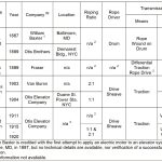
The electric gearless traction machine supplanted the high-speed multiply-reeved roped hydraulic elevator system in the early 1900s (Table 1). In the evolution of successful early electric traction elevator machines and rope drive methods, first came the worm-geared machine with a drum drive for the hoist ropes. Next came the gearless machine with traction drive, followed by the worm-geared machine with the drive sheave inserted in place of the drum, resulting in the traction drive. While the elevator industry at large used the V-groove on worm-geared traction-machine drive sheaves, Otis drive-sheave grooves moved to the undercut grooves (U/C) type based on Hymans’ analysis and design of the family of U/C grooves.
Drive-sheave grooves for the double-wrap gearless traction (DWT) elevator machines in the early 1900s were based on the round seat grooves first used on drum machines but with deeper grooves. Drive-sheave grooves on early Otis gearless machines in the early 1900s were described in an American Heritage article, much of the content of which was Otis sourced:
“One common variety, first put into use by Otis in 1903, is the gearless traction machine, powered by a variable-speed electric motor located at the top of the elevator shaft. This motor drives a large, deeply grooved sheave, over which [passes] a set of parallel cables that are fastened at one end to the top of the elevator and at the other to a heavy counterweight. . . . ”[7]
The reference to a “deeply grooved sheave” inferred that the round seat grooves deployed on the gearless machines were deeper. The description of it is consistent with groove technology for sheaves and drums, which has been followed since the dawn of wire ropes. Sheaves were designed and manufactured to have deeper grooves than drums. Drum grooves were typically shallow to accommodate side draw of the ropes as they underwent the fleet angles as winding or unwinding of the ropes occurred.
Ropes running in round seat drive-sheave grooves exhibited rope slippage in single-wrap traction (SWT) roping arrangements, thus necessitating deployment of a higher traction groove. Enter the V-groove for SWT roping worm-geared machine arrangements.
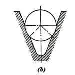
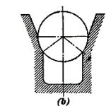
Early geared traction elevator machine drive sheaves starting in 1911 utilized V-grooves because of their high tractive capability attributed to the pinching of the rope within the groove. When the groove is new, the rope contacts the V-profile at two points at the respective sides of the V-groove (Figure 4 (a)) at points a and b, resulting in very high rope-to-groove pressures and high tractive effort. With the passage of time, the rope wears a rounded seat on both sides of the V-groove, (Figure 4(b)), thereby diminishing the pinching effect of the V-profile, inducing lower rope-to-groove pressures, which, in turn, results in a lessening of the available traction. As time goes on, the condition continues to worsen (Figure 4(c)). Once this occurs, the car continues sliding past the floor during slowdown, and accelerated wear between the rope and groove ensues. The only remedial action is to recut the sheave grooves to their original profile.[10 & 11]
In his 1897 patent,[8 & 9] Augustus L. Duwelius, while not making any claim of invention with respect to the drive-sheave groove available traction in his 28 patent claims, described the contemporary deployment of iron hoist ropes operating in V-grooved drive sheaves at the time:
“To secure the degree of engagement between the driving sheave and hoisting rope necessary to transmit the power to the elevator car, it has been the practice to provide the driving sheaves with grooves having two sides at an acute angle and resembling the letter V. The wedging of the hoisting rope in the groove, if sufficiently acute, insured the transmission of the motive power. The immediate effect of this upon the soft-iron rope employed was to pinch it out of shape, causing a change in the molecular structure of the wires, followed by the frictional wear to the outside of the rope incident to its repeated wedging in and release from the groove and its initial destruction within so short a service as to render its employment in this manner both unpredictable and dangerous. This was due to the pinch in the V-groove and the pressure resulting from the combined weight of the car with its load and the counterweight.”
Early in his career with Otis, Hymans recognized that a solution for the optimum sheave groove profiles was needed for SWT applications served by geared traction machines, the bread-and-butter market for Otis. Optimizing the traction capability for the geared market would accomplish two objectives: first, provide for a range of available traction values between that afforded by the round-seat groove and V-groove; second, reduce the rope and groove wear to a more reasonable level. Hymans posited that a groove profile arranged with the bottom portion of the groove cutaway (Figure 5(a)) would be effective in maintaining a fixed amount of available traction and adequate rope support as groove wear occurred, provided that the vertical support of the rope remained constant.
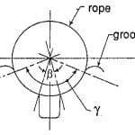
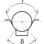
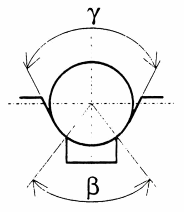
Hymans’ mathematical model was therefore predicated on maintaining a relatively constant vertical support for the rope as groove wear occurred. Referring to Figure 5,[10 & 11] a straight vertical U/C from points a to b is provided at the bottom of the groove, so that, as groove wear occurred, the rope would continue to have a relatively constant vertical support. In Figure 5(a), the horizontal width of the U/C is defined by the angle subtended by the letters aob, defined later as the groove U/C angle, β, (Figure 6).
An early commentary by an Otis spokesman at the time of the company’s first electric gearless traction machine contract at the Beaver Building, in New York City (NYC) in 1903 was memorialized in the “Otis Bulletin Special 125th Anniversary Edition,” which stated:
“With an elevator, six to eight lengths of wire cable, or hoisting ropes, are attached to the top of the elevator and wrapped around the drive sheave of the electric motor in special grooves. The other end of the cables is attached to a counterweight that slides up and down in the shaftway on its own guide rails.”
“The weight of the elevator on one end and the counterweight on the other presses the cables down on the grooves of the sheave. When the large electric motor turns the sheave, it moves the cables with almost no slippage.” [12]
The spokesman’s description of the ropes being pressed down in the grooves with almost no slippage is consistent with two extremes of the era: DWT with round-seat sheave grooves and SWT with V-grooves. However, the era of SWT for gearless applications would not occur for the better part of a century. Therefore, the commentary suggests that the early gearless traction machines were DWT, and the grooves were round-seated. The issue of rope slippage in round-seat grooves was minimized by the larger available traction afforded by the large angle of wrap,θ, resulting from the double-wrap roping.
The legacy theory posited by the Euler Eytelwein equation was insufficient in establishing the available traction between a radially contoured sheave groove and an essentially circular rope profile (Figure 6).
It is clear from Hymans’ early papers that the effective coefficient of friction that comes into play in applying the Euler Eytelwein equation at the rope-groove interface had to be variable, depending on the geometry of contact between the rope and groove surfaces.[13-19] This hypothesis set the stage for his mathematical analysis of the forces generated at the interface of the rope and groove to result in varying degrees of available traction, depending on the shape of the groove. In late summer/early fall 1920, Hymans undertook his preliminary mathematical analysis of the rope tractive effort at the rope-to-groove contact region.
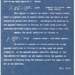
Reproduction technology was primitive in 1920 compared to later years. Aside from the original manuscripts of Fred Hymans’ work, the remaining option to obtain copies was to blueprint the documents. The originals of his Theory of Rope Traction are no longer available, but blueprint copies, covering the collection of papers, survived as blueprints, as seen in Figure 7.
To develop the mathematical model necessary to find the groove shape factor, Hymans posited:
- The sheave groove is entirely rigid and nondeformable.
- Groove wear occurs vertically.
- The hoist rope is a perfectly smooth cylinder.
- The rope cross-section remains circular as loads are imposed on the rope.
- Centrifugal effects of the rope are negligible.
- Due to large-diameter sheaves, there is negligible rope bending resistance.
- The initial wear-in period is not considered.
Hymans’ early manuscripts on the theory of rope traction were authored solely by him in 1920. These papers contained his fundamental treatises on several subjects, as follows:
- The radial force per unit length of rope[13]
- The magnitude of the groove pressures[14]
- The groove reaction per inch of rim[15]
- The apparent coefficient of friction[16]
- Traction[17]
- Single Wrap Traction[18]
- Creep[19]
Hymans posited that the most significant increase in traction can be achieved by changing the groove shape using the undercut groove, which increases the apparent coefficient of friction. He derived the mathematical relationship that would quantify the groove pressures at any point of rope-to-groove contact according to the following sinusoidal relationship:

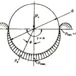
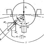
Equation (8) uses the variables shown in Figures 8, 9 and 15. The radial force, Pr, causes a pressure distribution over the lower boundary of the rope profile, thereby maintaining it in a state of vertical equilibrium. It is physically distributed over the regions of rope-to-groove contact. Such pressure distributions are shown graphically to a relative scale in Figures 8 and 9 for the groove configurations of round-seat and undercut grooves, respectively. For purposes of comparison, two grooves are shown.[1] In Figure 8, a round-seat groove is shown where the pressure decreases from its maximum, pmax , near the bottom of the rope profile contact with the groove to its minimum, pmin = 0, at the top of the groove. The mathematical model is for a slightly worn groove, such that the region of contact of the rope within the groove is shown for the case, where γ = 180° = π.
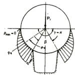
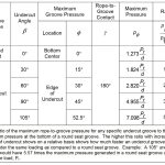
The groove pressure distribution in a slightly worn undercut groove is shown in Figure 9, where the pressures normally produced at the bottom of the round seat groove are no longer present due to the undercut. Therefore, since the vertical summation of pressure vectors must be in equilibrium with the radial force per unit length of rope, the pressure vectors must be exerted over a smaller region of groove contact, thereby inducing groove pressures higher than those found with the round-seat groove. The maximum groove pressures will occur at the two edges of the undercut. Under the same load, Pr, the maximum pressure at the edges of the undercut are increased. Table 2 shows the comparison of the maximum rope-to-groove pressures for each groove as a function of the maximum pressure induced in a round seat groove under the same load, Pr. Popular undercut grooves used in the industry are shown.
Hymans showed that the available traction could be increased by increasing the angle of undercut at the bottom of the groove.[1 & 14-17] There is a limit on the maximum undercut angle, since the larger the undercut, the less vertical support the rope receives from the groove, and, therefore, the less load we can put on the ropes without causing rapid sheave wear and rapid rope failure.
For this reason, the allowable load per rope decreases with a corresponding increase in the undercut angle.
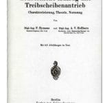
Several years after developing the mathematical theory of rope traction for traction elevator systems, Hymans and Axel V. Hellborn coauthored Der Neuzeitliche Aufzug mit Treibscheibenantrieb,[20] in which the theory of rope traction as developed by Hymans was explained in more analytical detail, and several more analyses and illustrations were added. It is also noteworthy that the theory of the oil buffer first documented in Hymans’ 1926 paper to ASME[23] was published in this book.
This book is the bible for the theory and practice of rope traction and oil-buffer design in the worldwide elevator industry. The relationship between these two engineers was their Otis affiliation, albeit on different sides of the Atlantic Ocean. Hymans was a research engineer in the chief engineer’s office at Otis’ executive offices in NYC; Hellborn was listed as engineering manager of Otis, New York. The additional geographic attribution to Hellborn on the title page notes Stockholm, which was one of the major European cities in which Otis had a large sales presence. However, the city would not have had an engineering office, since all Otis products designed for international deployment were designed in New York. Since David L. Lindquist was the Otis chief engineer, and Hymans reported directly to him, it can only be concluded that Hymans and Hellborn were contemporary colleagues with shared academic interests in the subject of rope traction, buffers, etc., but Hellborn’s role within Otis appears less notable than those of Lindquist and Hymans.
From Hymans and Hellborn, the apparent coefficient of friction is defined by the rope-groove shape factor, G, and actual static coefficient of friction, µ.
The English translation of the Table of Contents of the Hymans’ and Hellborn book is as follows:
“I. The characteristics of the traction drive lift:
A. The mechanical arrangement
B. The compensation of the weight of the suspension rope
C. The operational safety
“II. The theory of load transmission through rope friction, its nature and its characteristics:
A. The stress distribution in the rope above the traction sheave
B. The creeping of the rope (length change due to elastic nature of rope under stress)
C. The tension difference in the suspension ropes
D. Static and dynamic influences on the stress ratio
E. The surface pressure between rope and groove
F. The friction factor between rope and groove
G. The evaluation of the theoretical results
“III. The theory of the buffer devices:
A. Calculation of the spring buffer
B. Calculation of the oil buffer
“IV. Recommended practice in typification and standardization:
A. The essential significance of the range of performance
B. The series setup of machines and engines
C. Examples on standardization”[20]
Hymans postulated that, where there is radial conformance between the surface contour of the wire ropes and the supporting sheave grooves, the apparent coefficient of friction, fa, would be greater than the base coefficient of friction, µ, due to the material composition and geometry of the mating bodies. Hymans posited that there was a mathematical relationship that governed the numerical value for the apparent coefficient of friction. This relationship takes the Euler Eytelwein equation to a new level of analytical accuracy by introducing a rope-groove shape factor, G, that embodies the geometry of rope-to-groove contact and sinusoidal pressure distribution developed between the rope and groove.
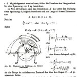
Starting with the derivation for the radial force per unit length of ropes,[13] Hymans mathematized the distribution of the groove pressure[14] resulting from the hoist rope bearing down against the groove contact surface (See Figures 11 and 12). From this, he was able to derive the magnitude of the groove pressures.[14] In the book [20], this groove illustration is given as Figure 35,P.57. In the original manuscripts, the angle subtending the undercut was given as a. In later years, a was re-designated as the available traction, and the undercut angle was assigned the symbol β.
From the groove pressures, Hymans determined the groove reaction per unit length of sheave rim,[15] from which he analyzed the radially directed pressure distribution over the regions of rope-to-groove contact, taking into account the regions of discontinuity where a groove undercut might be.[16] Once determining the resultant force acting radially from the rope center to the contact region on the groove, Hymans developed a trigonometric function for the rope-groove shape factor, G, which, when multiplied by the actual coefficient of friction, resulted in an apparent coefficient of friction. It is expressed as:

where the rope-groove shape factor was found as:
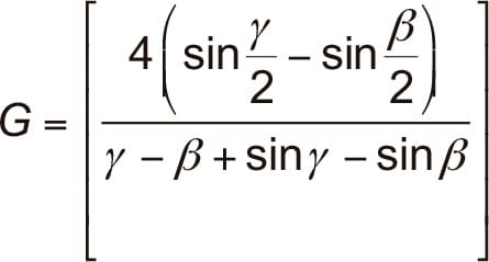
The general equation for the apparent coefficient of friction of steel-wire ropes operating on cast-iron drive-sheave grooves was derived by Hymans in the following general form based on substituting Equation (10) into Equation (9) to yield:
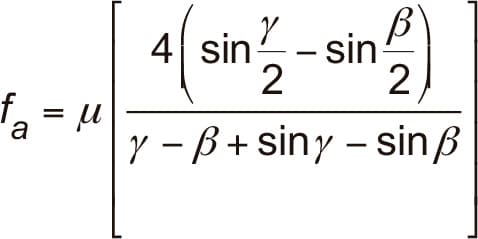
Equation (11) is the same form as the aforementioned one by Hymans and Hellborn. The ASME A17 Mechanical Design Committee, originally known as the A17 Mechanical Safety Devices & Machine Design Committee, discussed the mathematics of traction in the early days of A17 and opted not to include equations of application for rope traction in the design section of A17, preferring to leave it to the designers and manufacturers as proprietary. (The A17 philosophy of not advocating the use of A17 as a design textbook still prevails.) Decades later, the Europeans opted to include an EN 81 Appendix Section M[21] in which Hymans’ and Hellborn’s equations would be listed as informative. However, the EN 81 code writers showed the Hymans’ equation for the groove shape factor using the complementary angles. Hymans’ manuscripts show the apparent coefficient, Hymans’ Equation (5) in the form given by this article’s Equation (11).
Hymans’ 1920 manuscript sheets for the derivation of the rope groove shape factory are shown in Figures 16 and 17 for purposes of historical context and accuracy.
Hymans established allowable load per rope based on his theoretical analyses coupled with test data. A sample is seen in Figure 18. His lettering style rivaled that of a typewriter! Based on this, the Hymans’ reformulation of the Euler Eytelwein equation applicable to traction elevator drives is given as:
The author traces the Hymans’ mathematical derivations more fully in the DVD presentation. The drive sheave groove illustrated in the EN81-S0 Safety Code, Clause 5.11.2.3.1.1 is shown in Figure 19.
Based on the EN 81-1 description of the angles,[21] the corresponding apparent coefficient of friction based on Hymans’ theory was given as:
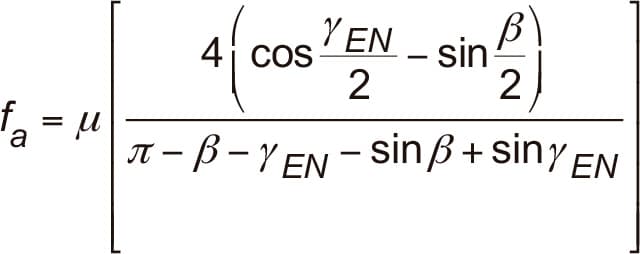
The proof of equivalence of groove shape factors between Hymans’ equation used in the U.S. and that used in the EN 81-1 code is found by substituting the following relationship into Equation 11:

References
[1] Gibson, G.W. “Rope Traction: Theory and Practice,” seminar, DVD format, Elevator World, Inc. (2009).
[2] German Patent No. 218 (August 1, 1877), Berlin.
[3] U.S. Patent No. 206,251, “Elevators,” Friedrich Koepe, Bochum, Prussia (July 23, 1878).
[4] Kempe’s Engineers Yearbook, p. K3/46, Koepe Winders (1988).
[5] Gray, Lee. “The Traction Elevator: Part One, Origins 1877-1891,” ELEVATOR WORLD, August 2004, p. 156-159.
[6] Lindquist, David L. “Outline of Elevator Development,” September 1937, presented to the ASME Transportation Section (fall 1938).
[7] Klaw, Spencer. “All Safe, Gentlemen, All Safe,” American Heritage, August/September 1978, Vol. 29, Issue 5, p. 43.
[8] Gray, Lee. “The Traction Elevator: Part Two, The First Electric Machines 1891-1899,” EW, September 2004, p. 129-133.
[9] U.S. Patent No. 595,874, “Electric Elevator,” Augustus L. Duwelius (December 21, 1897).
[10] Hymans, F. Electric Elevators, Book I, International Textbook Co., p. 25-27 (1931 & 1941).
[11] Hymans, F. Electric Elevators, Books I & II, republished by Elevator World, 1992.
[12] “Otis Develops Gearless Design,” “Otis Bulletin, Special 125th Anniversary Edition,” p. 3 (September 20, 1978).
[13] Hymans, F. “The Radial Force per Unit Length of Rope” (August 1920).
[14] Hymans, F. “The Magnitude of the Groove Pressures” (August 1920).
[15] Hymans, F. “The Groove Reaction per Inch of Rim” (August 1920).
[16] Hymans, F. “The Apparent Coefficient of Friction” (August 1920).
[17] Hymans, F. “Traction” (September 10, 1920).
[18] Hymans, F. “Single Wrap Traction” (1920).
[19] Hymans, F. “The Creep” (1920).
[20] Hymans, F. & Hellborn, A.V. “Der Neuzeitliche Aufzug mit Treibscheibenantrieb” (translated as “Modern Elevators with
Friction Drive Sheaves”), Verlag von Julius Springer, Berlin (1927).
[21] EN 81-1: 1998 Safety Rules for the Construction and Installation of Lifts – Part 1: Electric Lifts, Appendix M.
[22] EN 81-50: 2014 Safety Rules for the Construction and Installation of Lifts – Examinations and Tests – Part 50: Design Rules, Calculations, Examinations and Tests of Lift Components.
[23] Hymans, F. “The Emergency Stops of the Gearless Traction Elevator at the Terminal Landings,” ASME, New York, New York (December 6, 1926).
- Figure 1: Simplified elevator system
- Figure 2: Koepe friction hoist
- Figure 3: Koepe drive pulley with round seat and U-shaped groove
- Figure 4 (a-c): (l-r) New, slightly worn and worn V-grooves
- Figure 5 (a-c): (l-r) New, slightly worn and progressively worn U/C grooves
- Figure 6: Drive sheave rope and groove (Hymans’ version)
- Figure 7: Blueprint copy of Fred Hymans’ manuscript on Rope Traction
- Figure 8: Round Seat Groove Pressures
- Figure 9: Undercut Groove Pressures
- Figure 10 – Hymans & Hellborn 1927 Book
- Figure 11 – Title page of Hymans & Hellborn 1927 Book
- Figure 12 – Page 32 of Hymans & Hellborn 1927 Book
- Figure 13 – Page 62 of Hymans & Hellborn 1927 Book
- Figure 14: Hymans’ groove pressure model in his 1920 manuscripts
- Figure 15: Illustration of Hymans’ model showing the elemental force vector and components
- Figure 16: Hymans’ 1920 Derivation of the Apparent Coefficient of Friction, P.3 of 4
- Figure 17: Hymans’ 1920 Derivation of the Apparent Coefficient of Friction, P.4 of 4
- Figure 18: Hymans’ notes on the allowable load per rope
- Figure 19: Drive Sheave Rope and Groove (EN81-1 Version)
- Table 1: Evolution of driving means and traction grooves: early electric elevators and rope power transmission[6]
- Table 2: Maximum rope-to-groove pressures under the same load
Get more of Elevator World. Sign up for our free e-newsletter.
