Freight Elevator Door Control: An Opportunity for Wireless Technology
Feb 1, 2012

A comparison between hard-wired freight elevator door-control systems and wireless systems
by Steven Reynolds, P. Eng and Henry E. Peelle, III, DM
Introduction
To date, wireless technologies have found only limited application in the elevator industry. While a few access-lift manufacturers have applied wireless for call/send devices and some have applied Bluetooth™ to control setup, there has not been a general use of wireless for elevator controls. While adoption of wireless is limited, there is no prohibition of wireless technology in prevailing codes. The ASME A17.1/CSA B44 Safety Code for Elevators and Escalators does not prohibit the use of wireless technology for elevator functions. While the code prohibits the use of auxiliary wireless devices such as television remotes and radio-frequency identification tags not directly tied to the elevator, the code permits wireless devices or systems tied directly to the function of the elevator.
Learning Objectives
After reading this article, you should have learned that:
♦ ASME A17.1/CSA B44 allows wireless technology
♦ Wireless technology can signifi-cantly reduce the number and complexity of hoistway and car top wiring
♦ Individual wireless freight door controllers for each door and gate can eliminate a machine-room-mounted centralized controller
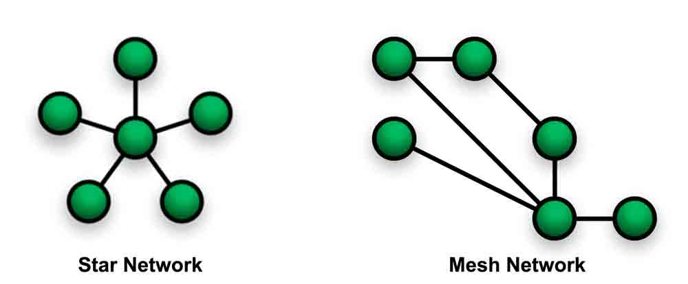
♦ Wireless door controllers can use a Wireless Personal Area Network (WPAN) in a “mesh” configuration as opposed to a “star” configuration
♦ Wireless door controllers need to meet and be tested to Federal Communication Commission standards.
With the proliferated use of wireless in applications such as mobile phones, Wi-Fi and Bluetooth, issues associated with elevator control immunity have become important. ASME A17.1-2000/CSA B44-00 included requirements for electromagnetic interference immunity on all control equipment, based on the European Marketing Confederation standard EN 12016. This standard ensures the elevator will not move unexpectedly when radiated noise is imposed on the elevator-control system. Surprisingly, adoption of immunity testing 10 years ago did not result in the adoption of wireless technology applied to the elevator.
Today, wireless communication is as reliable as wired networks. Other industries, including industrial automation, employ wireless systems incorporating safety integrity level (SIL) rated devices, with SIL ratings as high as those required by ASME A17.1/CSA B44. The time is ripe for the use of wireless in elevator-control applications. This article discusses one such application, the use of wireless for freight elevator door-control systems. Due to the many wires employed in traditional systems and the maturity of wireless technology, the application of wireless is an ideal fit for freight elevator doors.
This article discusses traditional hard-wired freight elevator door-control systems. This is then contrasted with a wireless system, focusing on the significant reduction in the number of wires required during installation. What follows is a discussion of communication methods and protocols. Before concluding, the article reviews regulatory testing and compliance.
Traditional Freight Elevator Door Control
To explain the advantages of a wireless connection, an understanding of traditional hard-wired systems is necessary. Most freight elevator doors and gates are individually operated by their own motors. As a result, each door and gate has its own set of positional limits or encoders. In addition, each door and gate has its own set of door-open, -close and stop buttons. Each landing door also has a zone switch, door interlock and an emergency unlocking device. The car gate also has a reversal device and gate switch. Wiring for these devices returns to the machine room, as series or parallel circuits, and terminates at a door controller located in a machine room.
Table 1 lists the number of conductors returning to the machine room for a front set of doors and a single car gate. Excluded are individual device wiring at each door and gate.
The first column of the table lists the electrical devices that need wiring for the doors and gate. The second column lists the total hoistway wires to connect the machine-room-located door/gate controller to the nearest landing door (either the top or bottom door, depending on the location of the machine room). This is also the same number of wires needed to connect each landing door to the next door in line and so on, until all doors are connected. The third column lists the total number of travel cable wires to connect the door/gate controller to the car gate. The fourth column lists the wires necessary to connect the door/gate controller to the elevator controller.
| Door and gate control electrical device | Number of hoistway conductors | Number of travel conductors | Elevator to door/gate controller conductors |
| Power | 0 | 2 | 3 |
| Landing door motor – two speed | 5 | 0 | 0 |
| Door open and close limits | 3 | 0 | 0 |
| Zone switch | 2 | 0 | 0 |
| Emergency unlocking device | 2 | 0 | 0 |
| Hall open, close and stop buttons | 4 | 0 | 0 |
| Interlock contacts | 6 | 0 | 6 |
| Car gate motor – two speed | 0 | 5 | 0 |
| Gate open and close limits | 0 | 4 | 0 |
| Retiring cam | 0 | 3 | 0 |
| Car-operating panel (COP) open, close and stop buttons | 0 | 4 | 0 |
| Light curtain | 0 | 2 | 0 |
| Gate switch | 0 | 2 | 0 |
| Inputs from elevator control | 0 | 0 | 7 |
| Outputs to elevator control | 0 | 0 | 3 |
| Total | 22 | 22 | 19 |
As the elevator control initiates door operation, the door/gate control must communicate with each other. Signals sent as outputs from the elevator control to the door/gate control are retiring-cam initiation, inspection operation, door-open initiation, door-close initiation, nudging and close warning buzzer. Signals received as inputs to the elevator control from the door system are door position (closed and open), reversal-device initiation, door-closed and door-locked status (interlock) and gate-closed status (gate contact).
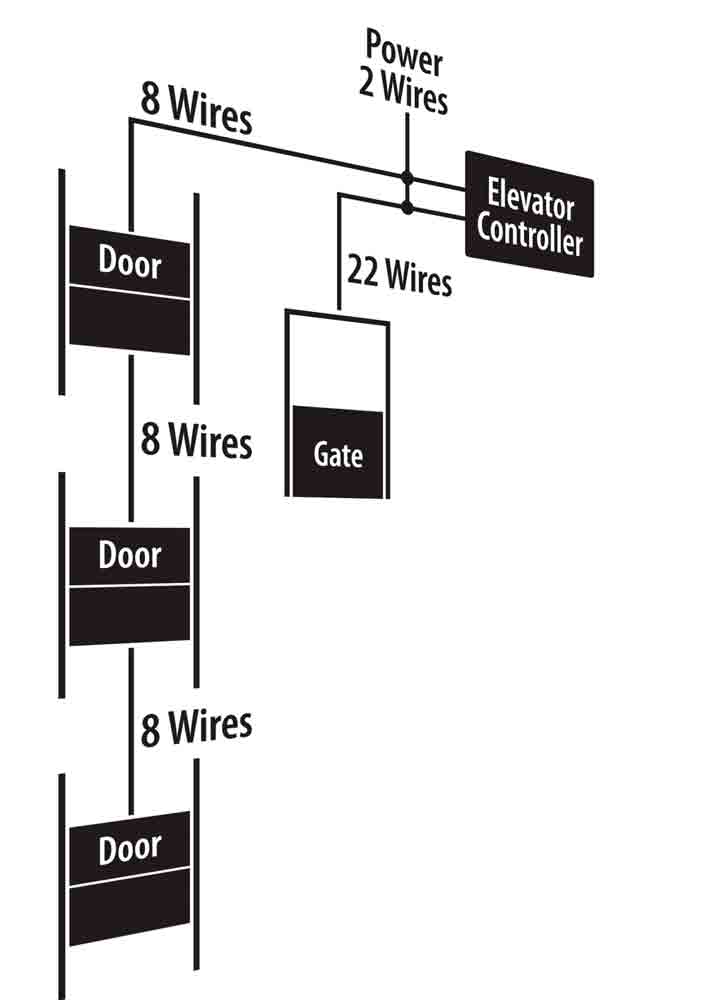
Figure 1 illustrates the number of connections in a typical hard-wired freight elevator application. As indicated, a typical three-stop freight elevator door system requires 66 wired connections (22 X 3) for the landing doors, 22 wires for the car gate, three power wires and 16 wires for controller-to-controller connections, for a total of 107 wire connections. When considering National Electrical Code requirements that all fixed wires run in either conduit or trough and union prohibitions against pre-wired connections, substantial field time is dedicated to wiring.
Wireless Freight Elevator Door Control
When stopped at a floor, the car gate and landing door are directly adjacent. However, electrically, they are much further apart. Wired connections between the car gate and landing door run through the travel cable to the machine room and back down the hoistway to the landing. Depending on the length of elevator travel, this distance could be significant. While wired serial communication reduces the discrete number of connections between landing doors, and between the machine-room control and the landing doors and car gate, the connection path between devices is still very long. Serial communication often requires special wire types and, in some cases, shielded cables.
Although fixed wired connections between the car gate and adjacent landing door are far apart, wirelessly, they are close together. In its simplest form, the only needed communication path is between the car gate and adjacent landing door. However, there are advantages to a system capable of monitoring the entire door system. Information on door conditions identifies problems with door operators. Door positional information provides a check on the closed or open status independent of the interlock. Signals indicating activation of emergency unlocking devices or showing the car is at more than one location point to problems needing response.
The Peelle Co. selected a mesh network using decentralized controls to minimize power required for radio communication. In a decentralized system, each landing door and car gate has its own wireless control. In the mesh network, each landing-door control “hands off” data to the next door in line. Each line of doors receives its own unique communication channel and unique address, usually the floor number. Figure 2 illustrates a mesh network and contrasts mesh with the more familiar star network.
Initiating close, in a decentralized wireless system, results when a discrete close initiation signal is output by the elevator control let in the machine room. The close signal travels down the traveling cable and is received by the car gate controller. Sequence operation requires the car gate to close before the landing door. Upon receipt of the close signal and after any dwell or warning, the car gate will close. In the wireless system, when the car gate has closed by 2/3, the car gate control will wirelessly communicate a close signal to the adjacent landing door, initiating landing-door closure.
Wireless communication between the landing door and car gate can extend to any number of initiations or controls. Landing-door open and close push buttons, when initiated, can transmit their status wirelessly to the car gate control from the local landing-door control to which they are connected. The car gate control then signals the elevator control that a user pressed an open or close push button via travel-cable connections. Figure 3 shows this communication path between a landing push button and the elevator controller.
Any number of signals can be transmitted wirelessly from the landing-door controller to the car gate controller and, subsequently, to the elevator controller, such as:
- Position of the landing door: fully open, fully closed or anything in between
- Hall open, close and stop push buttons
- Landing-door zone
- Unlocking-device condition
- Door reversing device or detector
- Motor condition, overload or over-duty
In a wireless system with decentralized controllers, local devices at each landing and on the car are wired to its respective controller. Wireless communication eliminates interconnections between landing doors. However, decentralization requires running lines for power, since each decentralized control directly drives the landing door and car gate motors. Table 2 lists the number of conductors returning to the machine room for a front set of doors and a single car gate employing decentralized wireless controls. Excluded is individual device wiring at each door and car gate.
As shown in column one, hard-wired and wireless controls use the same electrical devices. The second column lists the hoistway wires connecting the landing doors to the machine room. Since wiring of individual devices is local to the individual landing-door controller, the only connections are for power and interlock circuitry. The third column lists the total number of travel-cable wires connecting the elevator controller to the car gate controller. Devices local to the car gate wire directly to the car-top-mounted car gate wireless control. Wiring to the machine room consists only of power, push-button and signal wires. With no machine-room-located door control, signal wires return directly to the elevator controller, eliminating controller-to-controller interconnections.
| Door and gate control electrical device | Number of hoistway conductors | Number of travel conductors | Elevator to door/gate controller conductors |
| Power | 0 | 2 | 3 |
| Landing door motor – two speed | 5 | 0 | 0 |
| Door open and close limits | 3 | 0 | 0 |
| Zone switch | 2 | 0 | 0 |
| Emergency unlocking device | 2 | 0 | 0 |
| Hall open, close and stop buttons | 4 | 0 | 0 |
| Interlock contacts | 6 | 0 | 6 |
| Car gate motor – two speed | 0 | 5 | 0 |
| Gate open and close limits | 0 | 4 | 0 |
| Retiring cam | 0 | 3 | 0 |
| Car-operating panel (COP) open, close and stop buttons | 0 | 4 | 0 |
| Light curtain | 0 | 2 | 0 |
| Gate switch | 0 | 2 | 0 |
| Inputs from elevator control | 0 | 0 | 7 |
| Outputs to elevator control | 0 | 0 | 3 |
| Total | 22 | 22 | 19 |
Figure 4 illustrates the number of connections for the embodied wireless application. As shown, a three-stop freight elevator using decentralized wireless control reduces the number of wired connections to 24 for the landing doors and 22 for the car gate, and eliminated controller-to-controller connections in the machine room. The wireless system reduces wiring by 57% when compared to a hard-wired system (see Figure 1). Fewer connections and wires reduce the level of complexity, troubleshooting and opportunities for error. This directly translates into substantial savings in field installations.
Wireless Communication Protocols
A wireless personal area network (WPAN) interconnects each decentralized wireless control using a mesh network, as described earlier. A WPAN is analogous to a local area network which is commonly used for wired computer networks. Peelle selected the Institute of Electrical and Electronics Engineers (IEEE) 802.15.4 communication standard, which defines the network and data communication protocols for WPAN. This standard includes communication collision avoidance to ensure reliable and secure communications. This carrier-sense multiple-access (CSMA) protocol uses a listen-send-acknowledge procedure. CSMA allows the wireless control to reliably receive and send communications while in the presence of other wireless devices.
In carrier-sense protocol, the transmitting wireless device first listens for other carrier waves. The device then waits for a pause in ongoing transmissions before sending. Devices with multiple-access protocol are equally capable of receiving any transmitted data. However, use of a mesh network limits receipt of transmission to the next landing door in line. When the next landing door in line receives transmitted data, it acknowledges receipt to the sending device. This landing door can then transmit data to the next door in line, again following the listen-send-acknowledge protocol.
While every wireless device will, in sequence, receive, for example, a close initiation signal, not all landing doors will respond and initiate close. As previously described, a unique channel is assigned to each line of each elevator; only devices set for that unique channel can receive a close signal originating from a device programmed to communicate along that channel.
A door zone switch then limits which door in a line responds to the close signal. When the car arrives at a landing and lowers the retiring cam, unlocking the hoistway door, it also activates a zone switch. This zone switch limits any open and close signals received along the channel to that particular door. The zone-switch methodology is not new; zone switches are common on hard-wired systems of all types. However, use of the decentralized control allows status communication by each door along a channel. This makes it possible to detect if more than one zone switch is active, as would be the case when the car is at one landing, and authorized personnel activate an emergency unlocking device at another landing. The mesh-networked decentralized control will then suspend door operation.
Regulatory and Certification Requirements
To meet the requirements of ASME A17.1/CSA B44, wireless controls must be listed and certified to ASME A17.5/CSA B44.1 and pass electromagnetic immunity testing at levels associated with “safety circuits” in accordance with EN 12016. ASME A17.5/CSA B44.1 sets the minimum safety criteria for elevator control equipment. Moreover, when tested in accordance with EN 12016, the tested control must not:
- Render important electrical protective devices ineffective
- Permit motion of the car beyond the leveling zone when interlock or gate contacts are open
- Permit speeds to exceed the limits prescribed in the code
- Allow the car to revert to normal operation if it is in bypass
- Render ineffective interlocks, gate contacts, access switches or bypass switches
While similar requirements apply under EN 81, that also requires testing to EN 12015. In contrast to EN 12016, which tests the controller’s sensitivity to radiated emissions, EN 12015 tests and limits the amount of radiated and line-conducted emissions a controller can generate.
Testing requirements also come from the Federal Communications Commission, Industry Canada and European Commission, which regulate spectrum usage and other electromagnetic interference requirements. Federal and global standards applicable to wireless controllers include:
- Federal Code or Regulations – Grant of Equipment Authorization, FCC Part 15 Subpart C, Intentional Radiators
- Industry Canada – Certificate of Acceptance for Canada
- European Radio and Telecommunications Terminal Equipment – R&TTE Directive
- IEEE 802.15.4 – International standard wireless data communication protocol
Conclusion
This article reviewed the application of a mature but largely underutilized technology – in this case, wireless communication to freight elevator door controls. Wiring represents a significant portion of installation time. Control systems employing wireless communication can dramatically reduce the numbers of wires and connection points. Decentralization eliminates machine-room control, now essential with the widespread adoption of machine-room-less units. As described, wireless communication not only provides robust and simplified control, it is also a significant cost saver.
Learning-Reinforcement Questions
Use the below learning-reinforcement questions to study for the Continuing Education Assessment Exam available online at www.elevatorbooks.com or on page 94 of this issue.
♦ What advantages does wireless technology provide in a complex freight elevator door control system?
♦ What type of network arrangement was used for wireless freight elevator door controllers and why?
♦ List some of the information passed wirelessly from one door controller to another.
♦ What is floor zoning and what does the zone switch do?
♦ What certifications and listings are required for wire-less elevator devices?
Get more of Elevator World. Sign up for our free e-newsletter.


