Old-technology motors have no place in modernized elevators for many reasons.
This paper was presented at  Berlin 2018, the International Congress on Vertical Transportation Technologies, and flrst published in IAEE book Elevator Technology 22, edited by A. Lustig. It is a reprint with permission from the International Association ofElevatorEngineers
  (www.elevcon.com).
DC motor technology is now considered outdated. When modernizing old gearless elevators, it is recommended to replace DC hoisting machines with machines based on the latest permanent-magnet (PM) technology. Because DC machines have not been used in new elevator installations for the past 20-25 years, there is limited support available from manufacturers and small repair providers. Pulse-width modulation (PWM)-based DC drives place high stress on the windings insulation of the existing machine and increase the risk of bearing failure. Typically, the elevator traction sheave will be worn out, as well, and require machining or complete replacement. Furthermore, modern safety codes require a brake system that has two independent and separately monitored brakes, which might mean costly changes to the existing hoisting machine or other elements of the hoisting system.
Introduction
Main reasons to replace a DC gearless machine when modernizing an elevator:
- DC machines have not been used in new installations for the last 20–25 years, meaning there is limited support available from manufacturers and repair providers.
- New PWM-based DC drives providing a power factor of 1 place high stress on the existing motor-windings insulation, which increases the risk of damage to the insulation and, therefore, the need for costly repairs and an extended period of downtime.
- PWM-based drives also increase the risk of bearing failure due to the bearing currents generated.
- Silicon-controlled rectifier (SCR) technology has a poor power factor and is also becoming outdated.
- Alongside hoisting machine replacement, the traction sheave typically requires machining or complete replacement.
- Modern safety codes require a brake system that has two independent and separately monitored brakes.
- The cost of DC machines and spare parts is rising, because the few remaining manufacturers are producing increasingly lower volumes.
- To eliminate all the failure risks related to different components (windings, bearings, traction sheave and brakes) and to meet the requirements of modern safety codes, in many cases, the machine will need to be disassembled and taken to a specialized repair workshop. The cost of the repairs will easily exceed that of a new machine, based on state-of-the-art PM technology.
- Most universities no longer include DC motor technology as part of their engineering curriculum, meaning there is a shortage of young professionals with the required skills to maintain and modernize equipment that uses this technology.
Benefits of replacing a DC gearless machine with a modern machine based on PM technology:
- Safe, modern solution that fulfills the latest code requirements
- Greater overall system e–ciency reduces energy consumption.
- Machine and drive are designed and thoroughly tested to work together to provide superior ride comfort.
- In many cases, rope life is increased, as the optimum roping arrangement can be used.
- No lack of skilled maintenance technicians, since the same technology is used in new buildings.
- Spare parts are widely available.
Technology Trends
Gearless Machines
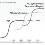
Figure 1 shows the most important technology trends in high-speed elevator machines since the invention of DC machines. DC machines have been used in medium- and high-speed elevators for decades, but by the late 1990s, they had been overtaken by asynchronous AC machines. This trend was not confined to the elevator industry — other industries also began adopting AC technology, because it was more reliable and easier to maintain. Because DC machines have not been used in new high-speed elevator installations for so long, the technology is considered outdated.
There are still tens of thousands of old high-speed elevators in operation with DC gearless machines as the key component of their hoisting systems. The hoisting system includes the ropes and roping arrangement with the required pulleys, the machine and its control components, the compensation system, as well the car sling and counterweight arrangements.
Because DC machine technology is no longer used in any major industry, the available volume of related components — such as the DC drive needed to control it — has decreased significantly, and the number of companies supporting the technology is diminishing rapidly. This has served to drive up the cost of components and increase the risk of poor spare-parts availability in the future.
Once an elevator has been in heavy use for about 20 years, component failures and other problems become more common, due to wear and tear. It may be di–cult to find spare parts, especially if the manufacturers of the original components were small companies that are no longer operating.
Control Technologies For DC Machines: Drives
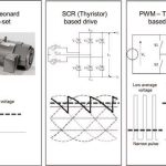
Figure 2 shows the three main control technologies that have been used to control DC machines. The Ward-Leonard Machine- Generator set, or “MG set” for short, provides smooth voltage to DC machines. This set was superseded by thyristor-based drives — also known as SCR-based drives — in the mid 1980s. Transistor- based drives using the PWM principle became more widespread in the early 2000s.
Many older DC machines were designed for MG-set technology and had a low insulation class; Class A, the lowest class, can be found in several old DC elevator machines. In general, Class A was used in household appliances and is not very common in real industrial applications requiring high reliability.[1]
Because of their operating principle, SCR-based drives typically have a poor power factor, which can lead to a high network current, as well as high losses in transformers and cables. Utility companies, in particular, are interested in the power factor and even have rebate programs in some markets to encourage building owners to upgrade their systems to achieve the best possible power factor.
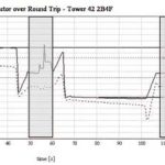
Figure 3 shows the measured power factor of a double-deck elevator powered by an SCR drive. The average power factor over the round trip was only 0.33.
PWM drives typically have a power factor greater than 0.95. The PWM transistor drive principle is that the transistors connect the maximum voltage to the machine for a short period of time. It is possible to achieve a controlled average voltage for the machine by controlling the length of this time period. While their high switching frequency and PWM principle enable good machine control and power factor, their high voltage spikes and fast du/dt result in heavy stress on the machine windings, which may result in damage to the windings insulation over time. The following sections examine this issue in more detail from thermal, electrical and mechanical points of view.
Risk of Damage to Windings With PWM Drives
Thermal Considerations
Thermal losses in an electrical machine depend on the load condition (duty point) and the form of the supply. Sinusoidal supply (for example, from a rotating transformer) results in the lowest losses, whereas PWM with relatively sharp pulses results in the highest losses. The thyristor-controlled DC drive supply sits between the two.
The overall e–ciency of the system is, however, significantly improved by moving from a rotating transformer to PWM, as the losses on the supply side are reduced. The additional losses of pulsed supply are due to current harmonics and the increased dielectric losses of the insulation itself.
If there is little or no margin in the thermal dimensioning of the machine, the increased running temperature (due to additional losses) may significantly reduce the machine’s thermal lifetime. The impact of these additional losses needs to be considered carefully if an old machine is going to be used with a new variable-speed drive. As a rule of thumb, the thermal lifetime of the insulation system is reduced by half with every 8-10°C increase in temperature.
Electrical Considerations
Sinusoidal supply provides the smoothest supply for an electric machine and the least electrical stress on the insulation. Similar to thermal losses, PWM stresses the insulation, mainly because of the high du/dt of the pulses, which changes the voltage distribution in the winding elements from linear (sinusoidal supply) toward nonlinear (pulsed supply).
The margin of the electrical dimensioning determines whether the increased electrical stress will result in a reduced electrical life. Even if the characteristics of the insulated winding and pulsed voltage were to remain at a level where no partial discharges appear in the winding, the increased surface and dielectric currents tend to decrease the electrical life of the insulation.
Mechanical Considerations
Sinusoidal supply results in the closest to sinusoidal current within the winding. On the other hand, PWM supply results in a wide spectrum of current harmonics that expose the winding elements to force harmonics.
Depending on the original design and, especially, on how the insulation system has aged, the vibration pattern of the winding elements may change significantly if the supply is changed (for example, from sinusoidal to PWM or thyristor-controlled DC).
Vibration of the winding elements tends to reduce the mechanical integrity of the winding, and, as aging progresses further, results in mechanical wearing of the insulation at slots and points where the winding elements support each other.
In the long term, wear caused by vibration is likely to age the insulation until normal operational stresses lead to it breaking down, if there is no other factor, such as thermal or electrical stresses determining the life of the insulation.
Machine-Room Environment
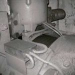
In the elevator machine room, the brushes of DC machines typically produce a lot of carbon dust, and there may also be small metal particles coming off the ropes and traction sheave. Old DC machines typically have very open structures, meaning it is easy for dust and particles to get inside the machine and into the commutator and windings. Since carbon and metal particles are highly conductive materials, they increase the risk of commutator or winding failure.
Figure 4 shows a machine room where metal particles from the ropes and traction sheave, as well as carbon dust from the DC machine’s brushes, have accumulated on top of the machine. Because of the machine’s open structure, these materials have penetrated it, resulting in a high risk of windings insulation failure.
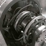
Figure 5 shows another DC machine with an open structure. The commutator and brush mechanism — the weakest and most sensitive components in a DC machine — may also require machining and repair, work that can only be done using special tools.
The brush type has a significant effect on how well the current flows from the brush to the winding. Because of the high level of wear they experience, brushes should be regularly checked and maintained. As the brushes wear, they release black carbon dust into the air, which, in many cases, finds its way into the building’s air-conditioning systems. If the commutator starts to show signs of “burning,” it should be repaired at the earliest opportunity by a qualified maintenance technician.
There are still companies that provide specialized cleaning services for DC machines in some countries. To clean and repair a DC machine, it needs to be disassembled in the machine room. Often, some windings will also need to be replaced during this process.
The armature winding is typically the most di–cult component to replace, and this work must be performed in a specialized workshop. Eliminating the risk of future winding problems requires specialized maintenance and repair by experienced technicians with good knowledge of DC machines. Because DC technology is now considered obsolete, finding technicians with the necessary skills and experience to perform the work is becoming increasingly difficult.
Risk of Bearing Damage With PWM Drives
Figure 7 shows a typical roller bearing used in high-speed DC gearless machines. The typical life for bearings is around 20 years. If a machine is about that age, there is an increased risk the bearings will already be worn out, even under normal operation.
Because of their high switching frequency, PWM transistor drives introduce common-mode currents, which can cause gradual damage to the bearings in the form of fractures and fluting.
In many cases, it is very di–cult to assess the actual condition of a bearing without dismantling the machine. The only reliable way to assess bearing condition without dismantling is by using specialized diagnostic instruments. A noisy bearing is the most common indication that damage has already occurred, and is a clear sign that a major and costly repair is required.
Modern AC machines are designed so that the common-mode voltage driving the currents is negligible or the bearings are insulated to prevent bearing currents from flowing.
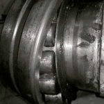
Traction Sheaves and Rope Wear
Traction sheaves also wear and, in many cases, will need to be machined or even completely replaced after 15–20 years. Typical reasons for the extensive wear experienced by these components are inadequate lubrication of the ropes or unequal rope tension.
Old high-rise elevators powered by DC machines are typically roped 1:1 or 2:1 and use a double-wrap roping arrangement: the rope comes from the elevator car to the traction sheave, then to the diverter pulley (also called the secondary sheave), returns from the diverter pulley to the traction sheave, then goes back over the diverter pulley to the counterweight.
In a double-wrap arrangement, the ropes bend several times, which shortens their life. Each bend also consumes energy. Modern and energy-e–cient high-rise elevators are powered by AC synchronous PM machines and use a conventional single-wrap roping arrangement. This arrangement provides the longest rope life and can be retrofitted as part of a hoisting-system modernization.
Safety Code Requirements
The latest elevator safety codes require mechanisms in place to prevent both unintended car movement when the doors are open and ascending car overspeed. In gearless elevators, the hoisting machine’s integrated brake system plays a key role in both of these situations. In terms of the requirements for the brake system, modern safety codes specify that there should be a minimum of two independent brakes that act and are monitored separately, are fast operating, and have su–cient torque and capacity to stop the elevator.
In many cases, the brake systems of old DC machines do not fulfill these requirements and need either costly modifications or additional brake systems, such as rope brakes, the installation of which further increases the system complexity and cost.
Figure 10 shows a brake system that has been fitted with two brake arms to meet the latest safety code requirements. The old brake magnet system, a single-piston system, would not have fulfilled the latest code requirements, because a stuck piston would prevent both brake arms from operating. Since these types of systems are typically one-off designs engineered by small repair companies, they require special approval from local authorities. Furthermore, sourcing spare parts will become a problem in the future. In general, implementing these kinds of custom-designed solutions is not advisable. Replacing the entire machine with a modern unit will ensure that the elevator fulfills the latest safety codes.
Summary
When modernizing old high-speed gearless elevators with DC hoisting machines, it is recommended the machine and related drive be replaced with a modern PM machine and AC drive technology. A system modernized in this way will minimize safety risks, comply with the requirements of the latest safety codes, and significantly improve the elevator energy e–ciency and ride comfort.
-
- Figure 1: Elevator machine technology trends
-
- Figure 2: The main control technologies used in DC machines
-
- Figure 3: Measured power factor of an SCR drive
-
- Figure 4: A DC machine covered in carbon dust and metal particles
-
- Figure 5: Old DC machine with open structure
-
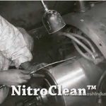
- Figure 6: Cleaning a DC machine (source: McIntosh Industries Inc.)[2]
-
- Figure 7: Close-up of a bearing in a high-speed gearless DC machine
-
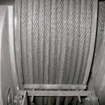
- Figure 8: Ropes on a traction sheave with a double-wrap arrangement
-
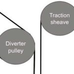
- Figure 9: Double- and single-wrap roping arrangements
-
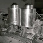
- Figure 10: Modifi ed brake mechanism
References
[1] Polka, Dave. Machines and Drives: A Practical Technology Guide; (2003), p. 81; ISA67, North Carolina.
[2] McIntosh Industries, Inc. YouTube video: youtu.be/V8xeOq0yXAs.
Get more of Elevator World. Sign up for our free e-newsletter.