Part one of this series (ELEVATOR WORLD, May 2013) traced the history of Gurney Elevator Co., from Howard Gurney’s purchase of National Elevator and Machine Co. in 1905 to his decision in 1911 to change the company’s name to Gurney Electric Elevator Co. Part two (EW, June 2013) focused on the creation of the Gurney Elevator Company Bulletin and included an examination of the company’s drum machines manufactured in the same period. This article will examine the Gurney Electric Elevator traction elevator and the company’s factory built in Honesdale, Pennsylvania, and completed in 1913. The examination of these topics will shed light on the development of the geared traction elevator and the early application of scientific management techniques to elevator manufacturing.
The final two issues of the Gurney Elevator Company Bulletin appeared in July 1912. Both were dedicated to providing readers with a thorough technical understanding of the Gurney Elevator Type K traction elevator, which had been developed in 1908/1909. The first issue contained a narrative account of the development of the Type K machine, while the second focused on the machine’s technical specifications (Figures 1 and 2). The narrative began with a brief history of the electric elevator from drum machines to the development of the gearless (one-to-one) traction machine. Gurney defined this type as a machine “where the electric motor is directly connected to the traction, or driving sheave so that when the motor makes one revolution, the driving sheave also makes one revolution – hence the name.” The one-to-one type was also described as having a specific design flaw, the solution to which drove the development of the Gurney Elevator Type K elevator.
| Gurney Elevator Co. Comparative General Balance Sheet | ||||
| Assets | January 1, 1910 | January 1, 1911 | January 1, 1912 | January 1, 1913 |
| Real estate, etc. | $97,796 | $108,895 | $185,218 | $369,046 |
| Bills receivable, materials, etc. | $69,932 | $113,655 | $114,227 | $150,219 |
| Cash | $3,655 | $2,039 | $5,471 | $3,426 |
| Uncompleted Contracts | $73,115 | $81,641 | $69,247 | $139,872 |
| Totals | $244,498 | $306,230 | $374,163 | $659,563 |
| Liabilities | ||||
| Capital Stock | $186,800 | $189,300 | $200,000 | $260,000 |
| Bonds | NA | NA | $94,500 | $195,500 |
| Bills and accounts payable | $14,351 | $18,671 | $42,655 | $98,701 |
| Surplus | $43,347 | $98,259 | $37,008 | $105,362 |
| Totals | $244,498 | $306,230 | $374,163 | $659, 563 |
According to Gurney, the primary design flaw in the typical one-to-one machine originated with the electric motor. He described electric motors as “naturally” high-speed machines that were forced to operate at “very slow speeds” when utilized in gearless machines. He claimed that to achieve a car speed of 600 fpm, the motor would only be required to operate at 63 rpm. This would, in turn, require the use of a “200-hp motor frame, where only 35 hp is needed.” The weight of the larger motor frame was estimated to be 13,000 lb. (in comparison to 4,000 pounds for a 35-hp motor), which made the elevator machine “excessively heavy” and necessitated additional structural support for overhead placement and the installation of permanent overhead cranes for maintenance. Gurney claimed the larger motors had a higher first cost, a relatively low efficiency, were difficult to control and had poor speed regulation. He also stated there was the “liability of frequent trouble with the brake, armature, commutator and controlling device.”
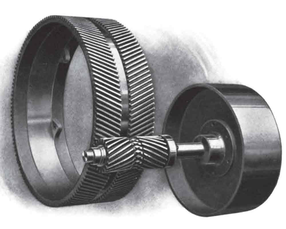
It is of interest that Gurney felt it was necessary to report when the company began development of a traction elevator system in 1908, “there were no patents to prevent our building the one-to-one traction type.” This “disclaimer” may have been perceived as necessary due to the litigious nature of several of Gurney Electric Elevator’s competitors, always willing to file lawsuits against patent infringements, either real or imagined. However, as noted above, Gurney was not content to build an “ordinary” one-to-one system – he sought to develop a design that overcame the perceived design flaw. His solution was a geared traction elevator that employed a helical or herringbone gear connection between the motor and driving sheave, which permitted the use of a 45-hp electric motor (Figures 2 and 3). Gurney claimed this elevator had “a greater efficiency than any other machine on the market,” weighed “less than half” of typical one-to-one traction machines and occupied “very much less space.” The Type K machine also featured the new Gurney Elevator Differential Limit Stop “operated by the car striking a rope at the beginning of the limit zones” and an improved controller design (Figures 4 and 5). The controller was reportedly based on “a plan never before followed” in which every contact was “of the make and break type and the contact made between copper and carbon.” A carbon element of the same size was used for all the contacts, which reduced costs and allowed for easy replacement.
Evidence of the success of Gurney Electric Elevator’s marketing campaign and product development is found in a “Comparative General Balance Sheet,” published in the 1913 edition of Poor’s Manual of Industrials: Manufacturing, Mining, and Miscellaneous Companies (Table 1). Of particular interest is the doubling of the U.S. dollar amount of “uncompleted contracts” between January 1, 1912, and January 1, 1913 (following a slight decline in the previous 12 months). This increase in business may be attributed to the anticipation surrounding the completion of the company’s new factory, which opened in April 1913. According to the Gurney Elevator Company Bulletin, the building’s design and proposed system of operation reflected “the efficiency methods originated by Mr. H.L. Gantt, which insures the manufacture of the highest-grade apparatus at the lowest cost.” Henry L. Gantt (1861-1919) was a mechanical engineer who had been associated with Frederick W. Taylor (1856-1915), author of The Principles of Scientific Management (1911) and creator of the time-saving organizational and manufacturing strategy that became known as Taylorism. Gantt was an equally well-respected management consultant and is best known for his invention of the Gantt Chart – a graphic organization and scheduling technique still used today for planning and controlling workflow.
Gantt’s organizational skills were required, because his company manufactured “practically every part” of its elevators. This necessitated having a diverse set of functional spaces: “Foundry” (for gray iron), “Brass Foundry,” “Casting Cleaning and Storage Area,” “Pattern Shop and Pattern Storage,” “Light Machine Shop,” “Heavy Machine Shop,” “Woodworking Shop,” “Dry Kiln,” “Forge Shop,” “Structural and Rails Shop,” “Electrical Department,” “Drafting Room,” “Tool Room,” “Assembly Department,” and “Storage and Shipping Department.” All critical functional areas were connected by a system of “industrial tracks” or small railways that facilitated the movement of work from one section of the factory to another. The primary track began in the rear of site and moved in a more-or-less continuous line to the Storage and Shipping Department at the opposite end of the building.
Raw materials entered the site via a rail siding that paralleled the building, with lumber stored adjacent to the main building and other materials stored in bins or piles at the rear of the site. The manufacturing process was predicated on the initial production of heavy castings in the foundry, which were then moved along the industrial track, with work done as needed by the supporting shops that lined the Main Hall (which contained the Heavy Machine Shop, Assembly Department, and Storage and Shipping Department). In addition to the track system, two ten-ton traveling cranes (one in the Foundry and one that passed through the Main Hall) also helped move components through the building. Finally, a “depressed” rail line entered the Storage and Shipping Department such that freight cars were at floor level to facilitate ease of loading.
The building also had two large “service rooms” that workers accessed at the start and close of the workday. Each worker was assigned a “steel locker” for personal effects, and the Foundry Service Room was equipped with “shower baths.” Six “toilet rooms” were located “at convenient points” in the factory and were accessible throughout the workday. The workers also operated in a well-lit environment. The building had ample exterior windows, clerestory windows over the Main Hall, Woodworking Shop, and Structural and Rails Shop, and employed a saw-tooth roof equipped with skylights over the Light Machine Shop and Electrical Department. In addition to ample natural light, the building employed a sophisticated interior lighting system designed by George H. Stickney (1872-1958) in collaboration with the building’s designer, Day & Zimmerman of Philadelphia. The exterior windows were fitted with “reinforced diffusing glass,” and the interior walls were painted white. The lights employed were tungsten lamps that ranged in size from 400 W in the Main Hall to 60 W in the Pattern Storage Room. All lamps were placed in Holophane D’Olier porcelain fixtures. Worker and facility safety was also ensured through the provision of sprinklers throughout the building; water for the sprinkler system was furnished by a 50,000-gal. tank located outside the building, adjacent to the Brass Foundry.
The Gurney Electric Elevator factory received an unprecedented amount of press coverage. It was the subject of three articles published from 1913-1916: “A Complete Elevator Manufacturing Plant” (Iron Age, July 10, 1913); “Lighting Considerations and Results in a Modern Plant” (Electrical Engineering, June 1914); and “Architecture and Industry (Illustrated Examples of the Work of Day & Zimmerman of Philadelphia),” (The American Architect, May 10, 1916). These illustrated articles permit a thorough look into the world of elevator manufacturing in the early 20th century. This information also raises questions about the factories of rival elevator companies and how they compared to this “complete elevator manufacturing plant.” Gurney, however, left little doubt regarding his relationship with his rivals. The final two issues of the Gurney Elevator Company Bulletin concluded with the following statement:
“The GURNEY ELECTRIC ELEVATOR COMPANY of Pennsylvania and the GURNEY ELEVATOR COMPANY of New York are not connected, either directly or indirectly, with any other corporation or individual engaged in the manufacture or sale of elevators.” Gurney’s emphatic commercial independence, coupled with his business skills, resulted in his election in 1914 as president of the Elevator Manufacturers Association. This recognition by his peers was a fitting recognition of his achievements up to this point in time and serves as an equally fitting conclusion to this series.
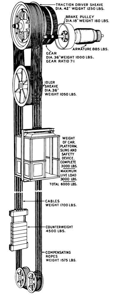
Figure 1: Type K traction elevator 
Figure 2: Type K traction elevator 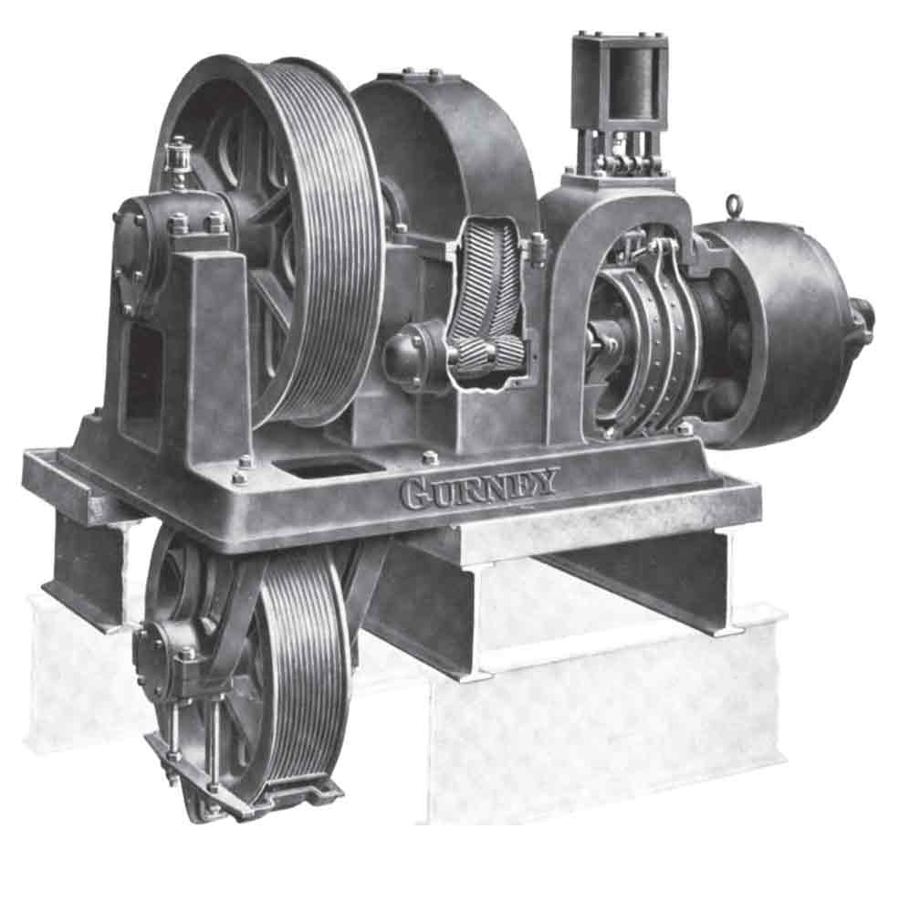
Figure 3: Type K-2 traction elevator machine 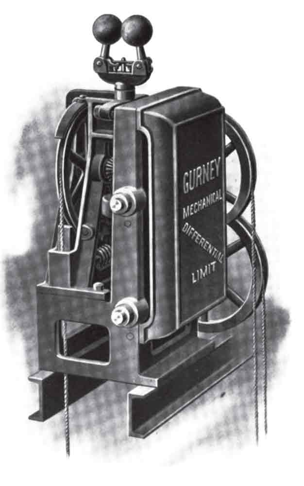
Figure 5: Differential limit stop 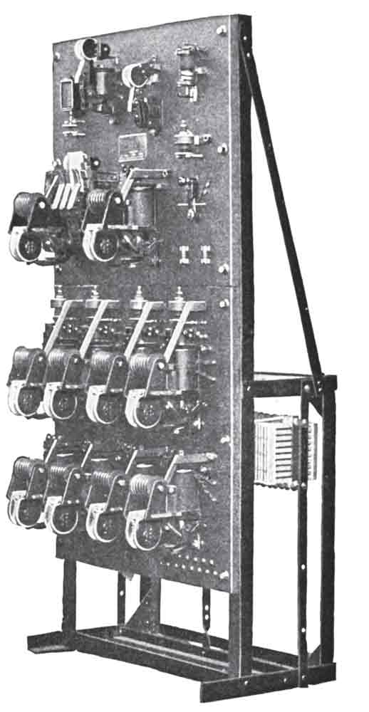
Figure 6: Type K controller 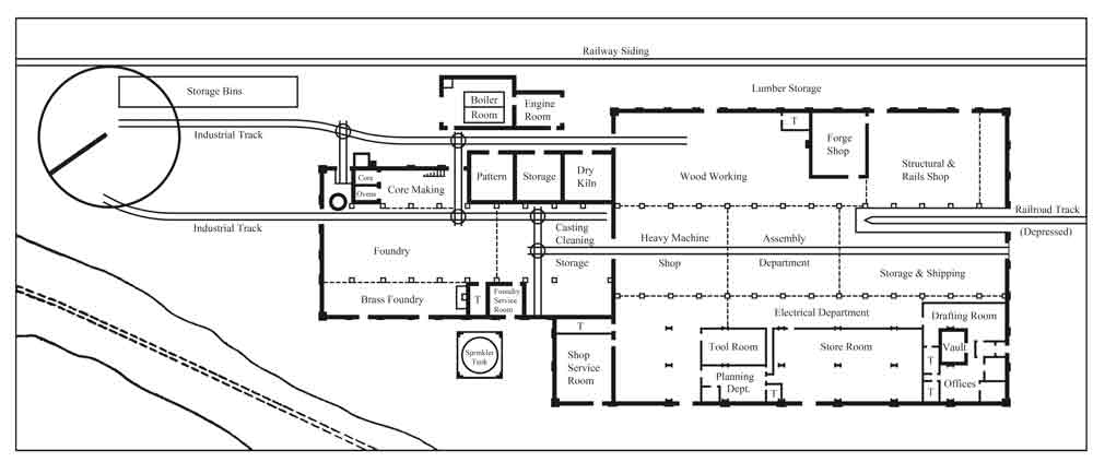
Figure 7: First-floor plan of Gurney Electric Elevator’s Honesdale factory (1913)
Get more of Elevator World. Sign up for our free e-newsletter.
