Helicopter Blade Lift and Safety Rail System
Jan 1, 2015
A custom solution for the U.S. Navy presents unique challenges.
Corpus Christi, Texas
submitted by John Linsley, Gene Richards and Gary West, Gillespie Corp.
At a U.S. Navy facility located within sight of the Gulf of Mexico in Corpus Christi, Texas, helicopter blades are spin balanced after being mounted to a spin shaft fixture located at the top of a 60-ft.-tall structural-steel tower. For many years, the existing conveyor system used to transport blades to the work platform and spin fixture had been troublesome, resulting in much downtime and loss of productivity. Maintenance costs had escalated, and more time was being spent repairing the conveyor than balancing helicopter blades. Gillespie Corp. was contacted by Bath Group Engineering and Commissioning and LNV Engineers, Architects, and Contractors. A solution was designed and built by Gillespie, then installed by ThyssenKrupp Elevator.
The Challenge
When Gillespie was first contacted, Bath Engineering described the existing equipment to the Gillespie engineering staff, headed by John Linsley, Engineering manager. The complexity of the existing system lay at the root of its failure and was exacerbated by the rust and corrosion brought on by the salty air of the Gulf. In addition to raising and lowering the helicopter blades to and from the top of the tower, it was necessary to design retractable handrails mounted to the fixed tower work platform. This was required, because helicopter blades sag before they reach operational rpm, and fixed handrails would interfere with the rotation of the blades. Furthermore, it had been necessary to manually install and remove the interfering handrails – a dangerous process requiring safety harnesses.
The Solution
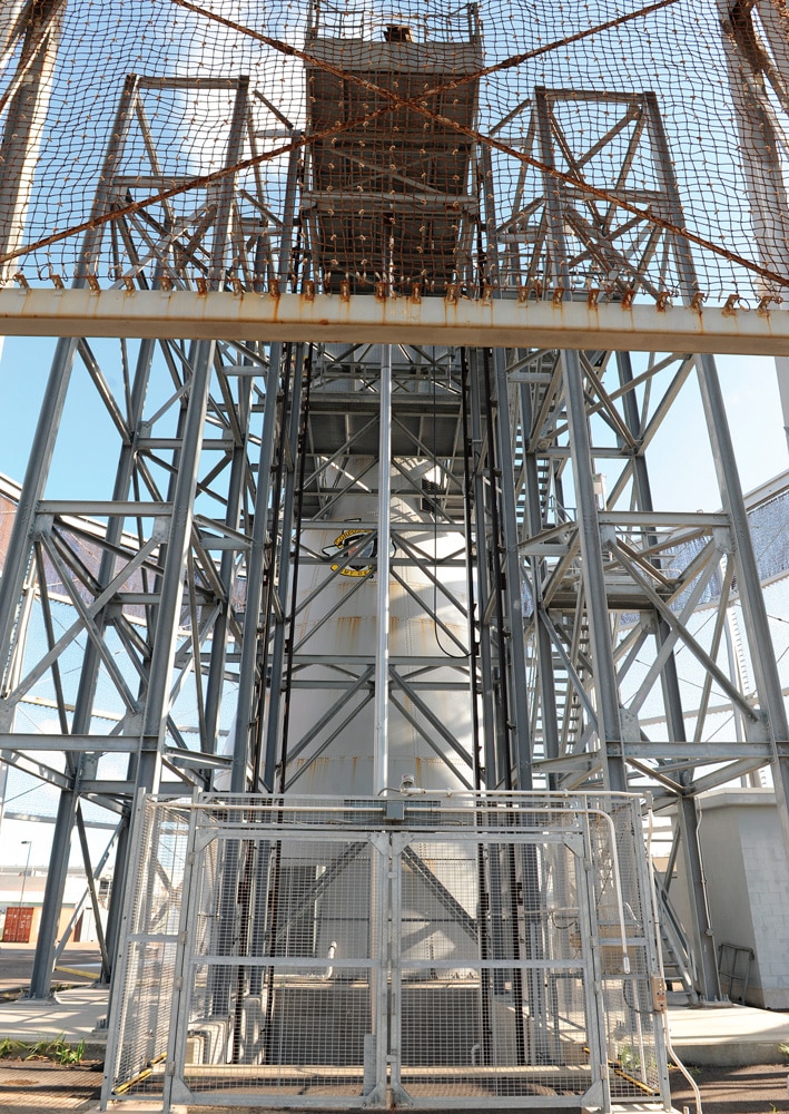
Gillespie proposed to drastically simplify the lifting procedure. Since the environmental conditions played havoc with the automated equipment, it was decided that a simple lifting platform would be built, with a cart specifically designed to cradle the blades. The platform was to be 12 ft. by 26 ft., 2 in.; the travel 58 ft., 9 in.; the capacity 5000 lb. at 50 fpm; and the pit depth 10 ft. The lift frame would be an underslung design running on four rails and lifted by a single in-ground cylinder with a 50-hp, submerged pump and motor.
The blades were to be moved about the facility while on the cart, and the platform lift would then bring this cart to the top of the tower. It was here (at the upper tower platform) that the handrails presented their challenge. Gillespie proposed to raise and lower the handrail sections using the compressed air available in the tower. Both the position of the handrails, as well as the lift platform, had to be monitored to prevent operation of the spin balance if either the lift or the handrails were not in their lowered positions. The platform lift would have an intermediate landing position located below the upper work platform while the blades are being balanced.
Gillespie then proceeded with fine tuning the design and constructing the required equipment. The entrance handrail is designed to be the same width as the platform and forms the landing sill when in the down position. The lift platform has fixed handrails along both sides and hinged, swing handrail gates at each end. Since the helicopter blades hang off the back end of the cart, a removable handrail section has been supplied for when the blades are on the lift platform. This center section of handrail drops between the short gates on the end of the lift that serves the lower landing, while the upper landing end has full-width swing gates. The gates were built with both locks and switches.
Each of eight powered handrail sections on the upper work platform has a single air cylinder with an adjustable flow control. The landing-sill handrail at the end of the lift platform has its own control valve, while all the rest of the handrail sections have one other control valve. Each handrail section has both upper and lower position switches, rated NEMA 4X. The air cylinders are supplied with soft-stop features, and the height of the handrails are the full stroke of the cylinders. When raised, the air cylinders are fully extended, and when lowered, they are fully retracted. The switches are there to report the position of the handrails, not to limit travel.
At the lower landing, there is a wire-mesh enclosure that completely encases the pit, hoistway area, and a considerable area between the platform sill and lower landing gate. This area is required by the overhanging helicopter blades. A large double-swing wire-mesh gate is built into the enclosure at the loading end of the platform beyond the area required by the overhanging blades. To prevent operation of the lift if someone is standing here, category-4 industrial safety sensors are positioned to illuminate the location. All interlocks, switches and electrical devices are NEMA 4 or NEMA 4X rated.
Control stations are located at the lower landing and at the floor below the upper work platform. In addition, there is a lift station with up/down buttons for the upper landing-sill handrail on the lift. The lift has up and down leveling switches, mid-level switches, and upper and lower limit switches.
To combat the corrosive environment, all structural steel was been sandblasted and painted with ZRC®, Cold Galvanizing Compound, and the vertical sliding portions of the powered handrails were built of stainless-steel tubing.
Operation
To operate the lift system, the lift is first called to the lower landing. The lower gate interlock is released by the car cam, and the gate is opened. The blade cart is then pushed onto the lift platform, and the gate is closed and latched.
The lift can then be sent to the upper landing from the lower station or called to the upper landing from the upper station. The upper landing station has both lift control buttons, as well as handrail control buttons. If the handrails are not in their upper positions, they must be raised before the lift can be operated.
After the lift has reached the upper landing, the landing-sill handrail is lowered, and the lift gates are swung out. The cart can then be moved onto the work platform to allow for the blades to be mounted onto the spin fixture. All the handrails will be up, and the work area will be secure. With the blades mounted to the spin fixture, the cart must then be moved back onto the lift, the gates closed and locked, and the landing handrail raised to its upper position. From the upper control station, the lift is then lowered to the midlevel landing, and the landing-sill handrail (in addition to the rest of the handrail sections) are lowered. With both the lift and handrails in a retracted position, the blades can be spin balanced.
After completing the blade balancing, the handrails are raised to their upper positions, and the lift platform is called to the upper landing. The landing-sill handrail is lowered, the lift gates opened and the cart moved back onto the platform. With the blades on the cart and the cart back onto the lift, the lift gates are closed once again, the sill handrail raised and the lift sent to the lower landing. There, the lower gate interlock is released, allowing the gates to be opened and the cart unloaded from the lift platform. To prevent operation of the lift in an unsafe condition, all the handrails must be in their raised position, the lower landing gate closed and locked with the interlock and the sensor screen unblocked.
Conclusion
Gillespie builds unique elevators, lifts and cranes. We undertake jobs that fall outside of the production lines of fellow companies in the industry. The helicopter-blade lift and powered retractable handrails presented unusual challenges. Once again, Gillespie feels it has demonstrated its ability to face a difficult challenge and arrive at a practical solution through imagination, engineering and manufacturing capability.
Credits
Equipment designer and builder: Gillespie Corp.
Equipment installer: ThyssenKrupp Elevator Hydraulics provider: ITI Hydraulik Contractors: Bath Group Engineering and Commissioning and LNV Engineers, Architects, and Contractors
Get more of Elevator World. Sign up for our free e-newsletter.

