Hoists, Teagles and Safety in the Early 20th Century, Part One
Oct 1, 2011

A look at the role of teagles and hoists in early elevators
The teagle elevator system holds a special place in the history of vertical transportation. Designed in the early 1800s for use in English textile mills, it was one of the first fully mechanized elevator systems. What is less well known is that the teagle remained an important component of British elevator technology through-out the 19th century, even surviving into the early 20th century. Evidence of this is found in W. Sydney Smith’s Report on the Construction, Arrangement, and Fencing of Hoists and Teagles of 1904. Following an apprenticeship and career with “various engineering firms,” Smith (1866-1945) was ap-pointed as one of “His Majesty’s Inspectors of Factories” in 1895, and his 1904 report was one of his most significant contributions. The report had been commissioned in 1902 by Sir Arthur Whitelegge (1853-1933), chief inspector of factories, in response to the Factory Workshop Act of 1901, which included new “fencing” or enclosure requirements for hoists and teagles employed in factories and other industrial settings. The 71-page illustrated report – the result of a two-year investigation – permits a detailed look into industrial elevator use and safety in the early 20th century.
In his introduction, Smith noted he had decided “to separate the subject matter into the two main sub-divisions of Hoists and Teagles, and these again have been further sub-divided into construction and arrangement [and] fencing and safeguarding.” The report included 41 plates of illustrations and was divided into the following sections: “Preliminary Definitions,” “Teagles: Construction and Arrange-ment,” “Teagles: Fencing and Safeguarding,” “Cage Hoists: Construction and Arrangement,” “Cage Hoists: Fencing” and “Safeguarding.” It also featured three appendices: “Causes of Hoist Accidents,” “Summary of Recommendations” and “Statistics of Hoist Accidents for the Year 1902.”
The necessity to distinguish be-tween a teagle and a “caged hoist” is evidence that the definition of the term teagle, which was originally applied to a system that employed a partially enclosed or “caged” car, had changed during the course of the 19th century. Smith offered his readers the following definition:
“The term teagle appeared in the earliest Factory Acts, and has been retained in subsequent amending of or consolidating Acts. In the absence of Statutory definitions the generally accepted view is that it applies to fixed lifting appliances on the form of a “cathead” or fixed der-rick in combination with a winch, by which goods are hoisted into or discharged from works, warehouses, or other buildings without the use of a cage or cradle, with or without the aid of mechanical power.”
He also observed that the term derived from “a north country dialect word signifying a lift or hoist.”
The designation teagle was thus restricted to hoists that employed hooks or slings to carry loads, such as sacks of flour or grain, or bales of cloth, typically from the street to the interior of a factory or warehouse. Smith described and illustrated various teagle types, ranging from simple friction devices to electric drum machines.
The section “Teagles: Fencing and Safeguarding” included a discussion of an unusual safety device – the Life Belt. It consisted of a “strong leather or canvas belt attached by means of a swivel hook to a stout radius rope suspended from an eye bolt in the ceiling and of such a length that a man wearing the belt. . . would be unable to fall more than a few inches should he accidently slip out of the [shaft] opening.” However, although Smith pro-vided a reasonably thorough discussion of the teagle (which included eight plates of illustrations with 26 individual drawings), the primary focus of the report was “caged hoists.”
According to Smith, hoists “have been understood to be appliances for the conveyance of persons or goods by means of cages or cradles traveling generally in vertical shafts or on fixed guides.” Following normal conventions, he divided the hoist types by their motive power: hand, steam, hydraulic (both direct ram supported and suspended systems) and electric power. Interestingly, Smith limited his discussion of hand power systems, although they constituted one of the most common hoist types, to a single sentence: “These are usually of such small capacity, slow moving, and scarcely call for further comment.” However, his discussion of steam powered hoists, which were doubtless rapidly decreasing in popularity in 1904, served as the primary means of introducing the reader to the critical aspects and basic components of caged hoists. Smith provided a detailed discussion of belt-driven machines, which included belt arrangements, pulleys, belt forks (shifters), brakes and starting (shipper) ropes. This discussion opened with an explanation of winding-drum and “friction driven” (traction) systems.
In this context, “traction” (a term not, in fact, used by Smith) referred to a very simple counterbalanced system:
“The most common method of driving the cage consists in suspending the cage from a rope or chain passing over a grooved pulley keyed on the driving shaft, supported by bearings at the top of the hoist-well. The free end of the rope is fastened to a heavy counterweight capable of sliding freely between guides in a suitable recess at the side of the well. . . . In practice several ropes are usually employed, passing over separate pulleys, if the hoisting rope is of hemp or Manila. With steel ropes or cables a single pulley with separate grooves may be employed.”
Interestingly, while traction systems were gaining in popularity in the U.S., Smith, perhaps reflecting a conservative viewpoint, claimed that winding-drum machines were the preferred system:
“A safer arrangement consists in driving the cage direct from a drum or barrel round which the hoisting ropes are coiled. The balance weight may be suspended by ropes passing over a second guide at the top of the well or by independent ropes coiled around the hoisting drum.”
He noted that the drum should be “provided with a spiral groove to facilitate the coiling of the rope” and that all “drum hoists should be fitted with automatic stop motion to prevent over running at the top and bottom of travel.”
The next section addressed ropes and chains. Although ropes (made of Manila, hemp or steel) were the most common means of supporting cages, chains composed of “short iron links” were also occasionally used. Smith noted that roping systems employed in many installations only gave the illusion of the cage being supported by multiple ropes:
“In many of the ordinary friction-driven hoists. . . a frequent plan is to fasten the two ends of a single rope separately to eye bolts in the top of the cage, and allow the loop formed by the center of the rope to pass round a pulley from which the balance is suspended.”
He then stated emphatically, “Such arrangements should be at once condemned.” The preferred method was to employ at least two independent ropes, each of which was capable of carrying the full load. This requirement was deemed to be of particular importance in hoists designed to carry goods and passengers. Smith also pro-vided three tables that listed the safe working loads and breaking weights for various sizes of iron chains, and hemp and steel wire ropes.
The next topic addressed was the hoist well (shaft), the walls of which should be “smooth and free from any pro-jecting obstructions such as beams, the ledges of over-hanging doorway lintels, the tops of window recesses, etc.” This description and its accompanying drawings clearly indicate that it was common practice to have win-dows in hoist wells. While these assisted in satisfying the requirement that wells should be “efficiently lighted,” the primary solution to this problem was a skylight located at the top of the shaft. According to Smith, the skylight also served an additional purpose:
“From the point of view of safety from fire it is prefer-able to light the shaft from the top by means of a ceiling light or glazed roof. Should a fire break out on the lower floors the hoist shaft usually acts as an excellent chimney and the flames rush up it to the top of the building. If the top of the shaft is built over, the flames, smoke, and heat will at once find their way through the hoist door into the top rooms. If the top of the shaft is simply covered with glass the heat will readily break the glass and allow the flames, etc., to escape in this manner often leaving the top rooms intact.”
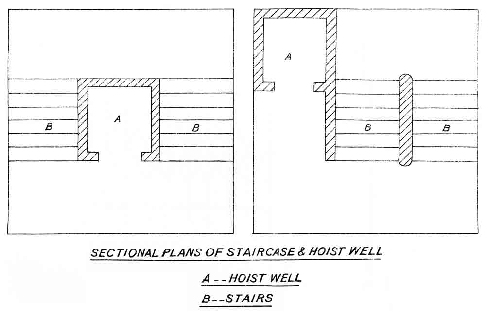
Although the shaft may not, in fact, have actually served the useful purpose Smith imagined it would in the event of a fire, at least he demonstrated an awareness of the potential danger it represented. The preferred plan arrangement was one in which the hoist was located not in the stair-well (as was common practice), but adjacent to it, where it would be less tempting for “persons passing up and down to tamper with the hoist.” This placement would also permit the space in front of the hoist to “be utilized, if necessary, for the storage of goods required to be carried by the hoist, leaving the stairs and landings free from obstruction.” The landings should be well lighted and, “if pro-tected by doors, clearly distinguished from the doors leading to rooms.” Finally, shafts should have a minimum pit depth of 3 ft. and a minimum clearance of 3 ft. between the cage and gearing at the top of the shaft.
The preferred cage design was one that had three sides “boarded in.” Smith believed that having “more than one opening. . . weakens the construction.” He noted, “It is a severe strain on the construction of any cage to throw goods direct from a lorry into the cage even if one opening only is pro-vided.” Smith also observed:
“Examples of hoists with two and three openings in the cage are continuously seen in which a little care and planning in the positioning of the hoist well would have obviated this defect. . . . Architects are chiefly to blame for this fault.”
He stated the “tops of all cages should be covered so as to prevent persons travelling inside from being struck by falling bodies.” The “cover” was typically composed of “stout wire mesh netting,” which protected passengers and admitted light into the car. Smith also briefly described cage guides and bearings and illustrated four typical plans of lifts designed to receive goods at street level.
Following this extensive and well-illustrated discussion of the essential components of normative hoist systems, Smith next described the basic operation and design of hydraulic hoist engines (both direct ram supported and suspended types), and electric hoist engines. The latter discussion was divided into two parts: machines designed to only carry goods or freight, and machines designed to carry freight and passengers.
It is of interest to note that in addition to providing a thorough description of a typical push-button-controlled, winding-drum passenger hoist system, Smith also mentioned Frank Sprague’s screw-driven electric elevator (ELEVATOR WORLD, July 2004):
“A type, which is practically limited to the electric express elevators of the U.S., consists of an electric motor coupled direct to a steel screw which revolves in a nut to which is attached a combination of pulley sheaves somewhat simi-lar to those in the suspended type of hydraulic hoist.”
It is almost impossible to imagine a more striking contrast than that between the architectural world of the American express elevator and that of the British caged hoist. This begs the question, “Why did Smith mention this elevator system?” The simple answer may be that he sought to demonstrate his awareness of current techno-logical developments. What is known is that in the second half of his report, which addressed specific safety devices, Smith demonstrated a thorough understanding of con-temporary British practices. These devices will be the focus of Part Two of this article.
Life Belt safety device, Report on the Construction, Arrangement, and Fencing of Hoists and Teagles, W. Sydney Smith (Plate 7, Figure 1) 
“Insecure Methods” of supporting hoisting cages, Report on the Construction, Arrangement, and Fencing of Hoists and Teagles, W. Sydney Smith (Plate 12, Figures 1 and 2) 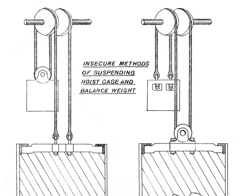
Hoist well plans (preferred plan on right), Report on the Construction, Arrangement, and Fencing of Hoists and Teagles, W. Sydney Smith (Plate 14, Figures 1 & 2)
Get more of Elevator World. Sign up for our free e-newsletter.


