Hydraulic Elevators – Configuring the Power Unit, Part II
Sep 1, 2011
This article discusses some of the basic concepts of hydraulic elevators and configuring their power units.
by Parag Mehta and Dr. Ferhat Celik
The first installment of this series (ELEVATOR WORLD, December 2010) gave insight into the selection of components like the pump, motor, flow control valve, cylinders and pipe rupture valve. This concluding article will serve as a guideline in the selection of components such as the hydraulic tank, oil and oil cooler. This article also explains how an elevator power unit should be properly commissioned so as to deliver trouble-free operation and how hydraulic piping can be optimally designed. Addition-ally, accessories that provide added safety will be covered.
Learning Objectives
After reading this article, you shouldhave learned about:
• The power unit of a hydraulic elevator
• Hydraulic tanks, oil and oil coolers of a power unit
• Selecting the correct tank, oil and oil cooler for a power unit
• Important guidelines for installing and commissioning a hydraulic elevator Piping in a hydraulic power unit
Introduction
Usually, little thought is given in selecting the tank and hydraulic oil used in an elevator power unit. Unfortunately, many have a misconception, like, “What is so technical about a fabricated sheet-metal tank and hydraulic oil?” In this way, oil coolers may be disregarded where necessary, and important accessories may be avoided due to lack of know how. Only the wrong selection of tank size and hydraulic oil could cause problems in the hydraulic elevator, which would fail to deliver despite the best components from reputed manufacturers. Considering some basic principles would not only give the power unit the needed thermal stability, but, in return, maintenance and trouble-free operation.
It’s not uncommon when power-unit manufacturers hand over systems to the elevator companies that, at times, have little or no experience in commissioning hydraulic elevators. Improper handling of the system, lack of protection against onsite dust (where construction is ongoing) and inadequate commissioning of the entire system adds to the problems.
The Biggest Component of the Power Unit: The Tank
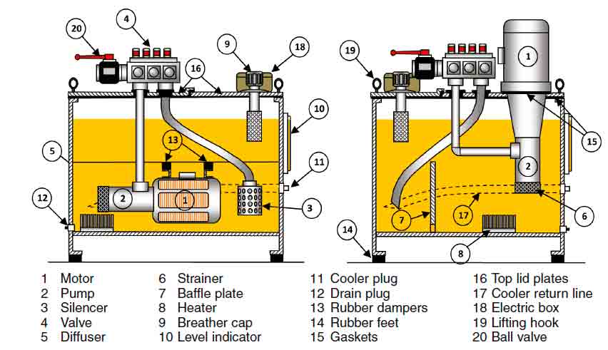
A hydraulic tank stores oil. While it is simple to think of a tank as an enclosed container, there is much more to it. There are different types and forms of tank available but the most commonly seen would be something similar as shown in Figure 1. Depending on the power unit’s de-sign and make, nonmetallic tanks unsuitable for heat dissipation are supplied by some manufacturers. A hydraulic tank fulfills the following main functions:
- Housing the pump (and, in some cases, motor)
- Oil storage
- Heat dissipation
- Provides a place for hydraulic fluid expansion
- Supports the unit
Conventional machine-room installations are slowly giving way to machine-room-less (MRL) hydraulic installations in the home lift segment. Here, the tank is often hidden and compact, and often found under a staircase or in a closet (Figure 2).
It is often debated about how big the tank has to be. As a rule of thumb, tank size should be calculated by a factor of two to two-and-a-half times the pump output. That means if the system has a pump delivering 60 liters per minute, the tank should be big enough to contain 120-150 liters of oil, plus an additional 10% space for air cushion. However, the tank size and volume of oil that it holds have to be chosen keeping in mind the thermal balance of the system. In no circumstances should the oil level drop below the pump inlet, which would cause the pump to dry run and create a whirlpool effect. The heat generated in the system is effectively transferred to the environment from the sides of the tank; therefore, a tank volume with the largest possible sides (in the shape of a square or rectangular prism) is most desirable. These have the largest heat-transfer surface per unit volume. Hence, where possible, the profile of the tank should be deep and narrow, rather than shallow and broad. Heat dissipation can be improved by increasing the surface area of the tank and mounting it on legs to raise its bot-tom by at least 150 millimeters from the ground level. This also provides easy servicing and draining of the oil.
A slightly thicker plate is used for the bottom plate and heavier plates for the top lids are utilized to ensure vibration-free operation, especially with external motors. If the tank is made of metal sheets, both its exterior and interior should be painted. Onsite tempering of the power unit can also be prevented by designing the tank such that the lid covers the control valve and other components in the system (Figure 3). This also helps isolate the system from the grimy environment and makes the power unit quiet.
When installing hydraulic elevators in such places as shopping malls or airports where the units handle heavy traffic, it would make a lot of sense to select an oversized tank that could contain more oil, thus decelerating the heat generation and increasing the heat dissipation of the system. The same principle applies for warm climates, where the ambient temperature often soars in summer. Fabricating a bigger tank and having more oil would only amount to slightly more initial investment and offer a considerable daily advantage throughout the lifecycle of the elevator.
The Fluid in the Power Unit: Oil
Hydraulic oil transmits the energy generated by the pump to the cylinder. Thus, it is an important medium of energy transfer, and its selection should be well considered. Ideally, the hydraulic oil should have the following characteristics:
- Stable viscosity with changing pressure and temperature
- Stable chemical and physical characteristics
- Good heat dissipation qualities
- Fire resistance (if regulations require)
- Good lubrication characteristics and ability to prevent rust formation
- Low coefficient of expansion
- Nontoxic, easy to handle and readily available
The best hydraulic fluid for elevator application is one with a relatively low change in viscosity when the oil temperature changes. The temperature and viscosity of hydraulic oil is inversely related; that means that oil viscosity decreases with an increase in temperature. For example, oil quoted as conforming to ISO 22 will have a viscosity of 22 square millimeters per second (cSt) at 40°C. However, the same oil would have a kinematic viscosity of 7 cSt at 80°C. While selecting the viscosity grade for a particular elevator system, starting viscosity at minimum ambient temperature; maximum expected operating temperature; and permissible and optimum viscosity range for the pump, motor and control valve should be taken into consideration. Applications in which the hydraulic elevator is going to experience heavy traffic coupled with warm ambient temperatures should preferably use oil with a higher viscosity index (VI) after checking with the component manufacturers about its suitability.
VI is a single-number representation of the viscosity temperature characteristics of a fluid. The greater the VI, the smaller the variation in viscosity for a given change in temperature, or vice versa. Oils with a VI of 80 or more are said to have a high VI value. Oils with a VI between 80 and 40 are considered to have a medium value, and those below 40 have a low value.
The Thermostat of the Power Unit: The Oil Cooler
The first law of thermodynamics states that energy cannot be created or destroyed – simply transformed from one type of energy to another. In a hydraulic elevator system, energy must be added to the hydraulic oil in order to elevate the car to its destination. An energy source such as an electric motor is needed to drive a pump to convert the mechanical energy into flow. Resistance to flow in the hydraulic system creates pressure, which energizes and actuates the cylinder. Hence, the complete hydraulic elevator system is actually an energy transfer system.
Inadequately adjusted pressure relief valves, improper oil viscosity, high ambient temperature, incorrect tank location, poor ventilation, insufficient tank size and tank design, and power units exposed to sunlight are some external factors that can reduce a hydraulic system’s capacity to dissipate heat. One of the main objectives of power-unit design is to balance heat losses at an accept-able oil temperature by the natural transfer of heat from the oil to the pipes, actuators and reservoir, and subsequent dissipation into the air. The heat (thermal) balance temperature calculation requires a true mathematical summation of heat entering and leaving the hydraulic system. In order to obtain a realistic estimate, many factors (both internal and external) are to be calculated simultaneously. Some of these are:
- Average load factor of the elevator
- Average trip factor
- Average motor starts per hour
- Total trip time
Heat dissipates from a hydraulic system in two ways: through natural convection and forced convection. Because of the temperature gradient, natural convection takes place as heat moves from the various system components to the surrounding air. It is preferable for natural convection to dissipate all the heat generated by the elevator system. In this case, generated and naturally dissipated heat balances at a temperature that should be below 60°C for a longer oil life (Figure 6). Using an electronic valve and the external motor can reduce thermal balance temperature by approximately 21%. If, on the other hand, natural convection cannot remove generated heat, the system temperature will continue to rise. An oil cooler is generally required when the heat generated by the system is more than what the system can dissipate (forced convection).
If the elevator system is optimally designed, oil coolers are generally not necessary; however, the decision as to whether a hydraulic-elevator power unit should have an oil cooler can only be decided after calculating the thermal balance of the system. However, if an oil cooler is used, it is necessary to place it in a machine room with proper ventilation.
Types of Oil Coolers
Air Oil Coolers
Air-cooled heat exchangers are generally used in hydraulic-elevator applications. A thermostat switches the cooling circuit on and off. The operating temperature of the thermostat contact can be set from the outside by means of a hand wheel. The sensor element is immersed into the oil. A pump is used to deliver hot oil from the tank to a heat exchanger. Oil is cooled there by a motor-driven fan, utilizing a process similar to the water cooling system in an automobile. The cooled oil is then pumped back into the tank for use by the hydraulic-elevator system. The exchanger is either fitted onto the oil reservoir or nearby, or is installed on the wall of the machine room. The calories (or the amount of heat transfer) depend on the size of the cooler. Thermal balance calculations help derive the amount of heat generated by the system against the amount naturally dissipated. If the amount of heat naturally dissipated by the system is less than what the system generates, a cooler with an appropriate heat transfer rate suitable for neutralizing the excessive heat should be selected.
Refrigerated Oil Coolers
Refrigerated oil coolers are rare but can also be found in installations where the ambient temperature is very high and the elevator is used very frequently (such as shopping malls, hospitals or exhibition centers). A refrigerated oil cooler works very much on the principle of a refrigerator. The warm oil from the tank (circulated by means of a pump) exchanges its heat, with the coolant being circulated in the refrigerator by a compressor. Thus, the oil is quickly cooled and delivered back to the hydraulic tank.
Installation of the Power Unit
The project of installing a hydraulic elevator often involves more than one company in the complete process. The company that installs the elevator on site often sources components and the power unit from different suppliers. The power unit, along with the cylinder and sometimes other accessories, is delivered by a supplier that specializes in the design, manufacturing and assembly of hydraulic-system components. It is very important that different vendors collectively fulfill the requirement of the end user and understand the basic facts of material handling and installation principles in order to deliver a problem-free solution.
A dusty environment, contamination and poor maintenance often create problems even before the elevator is installed and starts working. At times, the unit and hydraulic equipment are delivered, while other construction work is ongoing. Sometimes the equipment lies on the site for days before the elevator installation finally begins. In such a case, it should be properly concealed and protected from the environment.
Hydraulic piping done onsite should be checked for remains of welding burrs and metal slivers that remain in the pipe if not properly flushed. These fine metal particles have the potential to damage oil seals, O-rings and block filters in the circuit, which could result in expensive repairs and replacements even before the first run of the elevator.
As a hydraulic tank is an oil reservoir for the complete hydraulic system, any contamination in it can become the primary source of problems for the complete system. A tank inspection for cleanliness should be carried out before making the power unit operational. Oil should only be filled in the tank using proper filters. Pouring the oil into an unclean tank without filtering or checking the state of the tank can result in classic system failures that can be seen in the first few runs of the elevator. Dirt can accumulate on the ram during transport, and storage should be carefully cleaned before putting the cylinder into operation to safeguard oil seals.
The Nerves of the Power Unit: Hydraulic Piping
Hydraulic tubes, pipes and hoses interconnect the pump to the control valve, the control valve to the cylinder and other accessories used in the power unit. Hydraulic systems can use steel or galvanized pipe, but the latter is not recommended, as the zinc coating can react with the oil in an unfavorable manner. The lines, including the fittings, must be capable of withstanding calculated maximum system pressure and the surges created within the system. It is very important that the piping used possesses the required cross-sectional area large enough to handle the required flow rate without producing large pressure drops. The volume of oil that can pass through the pipe/tube/hose in a given period of time can be calculated by using the equation before deciding the diameter of the pipe:
Flow = 6A*V (Equation 1)
where “Flow” is the flow of oil in Cu.dm/m, V is the oil velocity in mps and A is the inside area of the pipe in square centimeters.
A pipe is identified by its wall thickness and schedule number. Since hydraulic-elevator applications usually do not go above 100 bars of operating pressure, they fall into a low- to moderate-pressure system and schedule 80 pipes are normally used.
Hydraulic hose pipes used in piping are graded by pressure, temperature and fluid compatibility. They provide flexibility and are used to connect the control valve to the cylinder where pipes or tubes cannot be effectively used. The grade SAE100 R2 is generally used in the hydraulic elevator industry. The inside diameter of the hose must be adequate to keep pressure loss to a minimum and avoid damage to the hose due to heat generation or excessive turbulence.
The hydraulic hose bend radius should be strictly followed as per the manufacturer’s instructions, as failure to do so can result in bursts that can cause injury or death. The weakest part of the hose is generally the terminating area or steel fittings, which are swaged at the end. Improper and incompatible fittings could be equally dangerous during operation. Hoses should never be twisted or pulled, but instead carefully sized and properly sup-ported, if necessary.
The use of couplings and connectors is inevitable in piping. There are some common misconceptions about these, such as, “If a coupling is compatible with a hose that meets SAE or EN specifications, the coupling will work with all hoses that meets the specifications.” This is simply not true. When making or buying an assembly, it is strongly recommend that the hose and fittings all come from the same manufacturer. That’s because dimensional tolerances listed in the standards are quite broad. Hoses not manufactured with tightly controlled dimensions might still meet the standards yet be difficult to assemble and perform unsatisfactorily due to compression variations when couplings are crimped on.
Conclusion
Hydraulic tank design and oil selection are important parameters in building a trouble-free power unit. These two together contribute greatly to heat dissipation and the natural cooling process. With proper design considerations and a properly ventilated machine room, coolers are generally not required. It is necessary to perform a thermal balance calculation of the elevator system in order to guarantee optimum performance, which pays back throughout the complete lifecycle of the elevator system.
Learning-Reinforcement Questions
Use the below learning-reinforcement questions to study for the Continuing Education Assessment Exam available online at www.elevatorbooks.com or on page 181 of this issue.
• What are the important criteria in selecting a hydraulic tank, oil and an oil cooler for a hydraulic elevator?
• Give some characteristics of the oil used in hydraulic elevators.
• Which factors should be considered while calculating the heat balance of the hydraulic elevator?
• What care should be taken during installation of a hydraulic elevator?
• Briefly explain the principles of hydraulic piping.
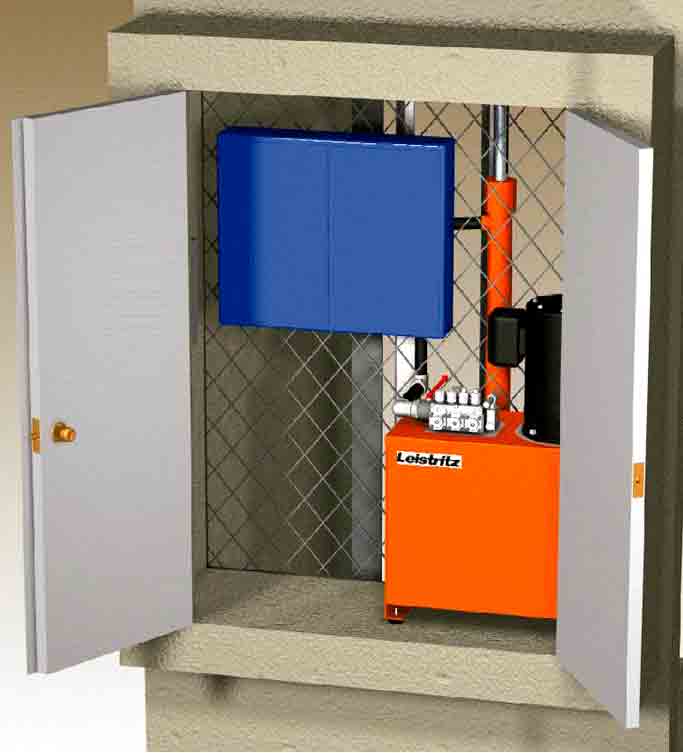
Figure 2: An MRL hydraulic power unit in a closet (photo courtesy of Leistriz) 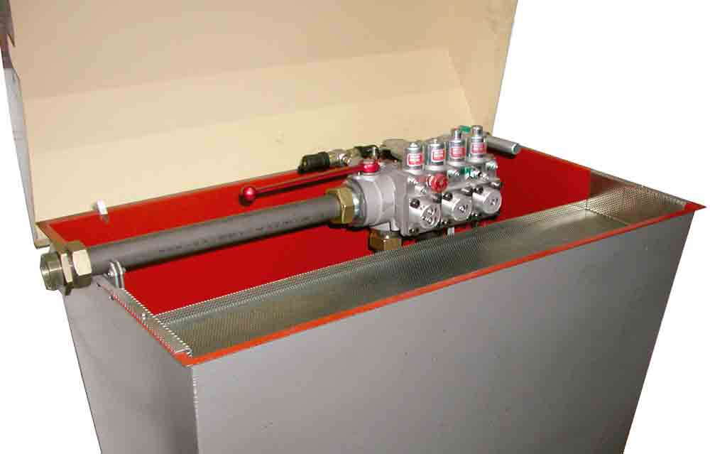
Figure 3: A hydraulic power-unit tank with lid to conceal the control valve 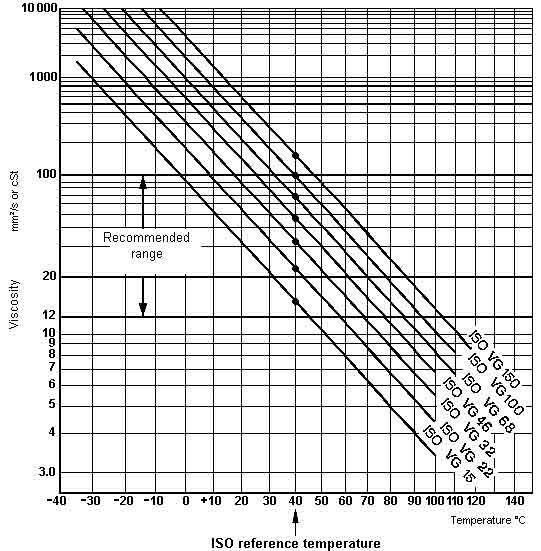
Figure 4: Viscosity grade table 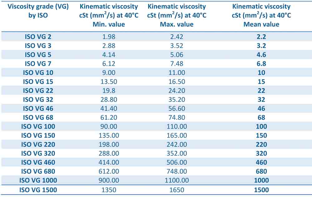
Figure 5: Viscosity grade of oil classified as per ISO 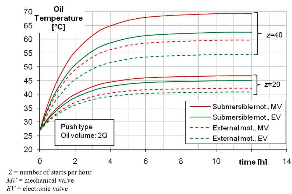
Figure 6: Effects of motor and valve types on thermal balance temperature 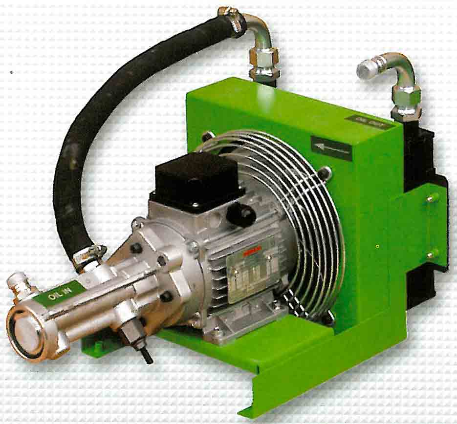
Figure 7: An air oil cooler (photo courtesy of Seim, Italy) 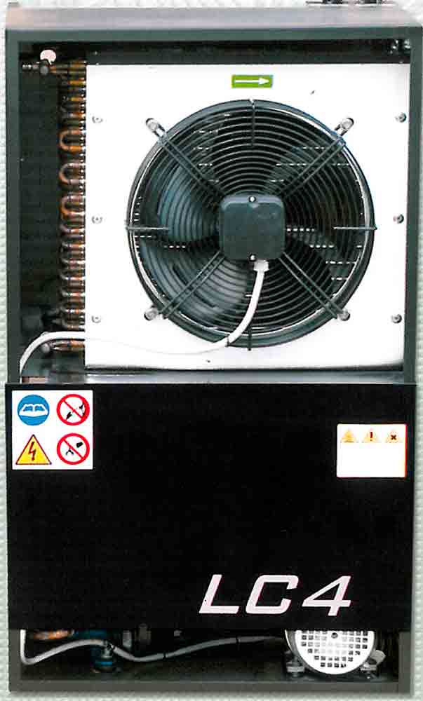
Figure 8: A refrigerated oil cooler (Courtesy: Seim) 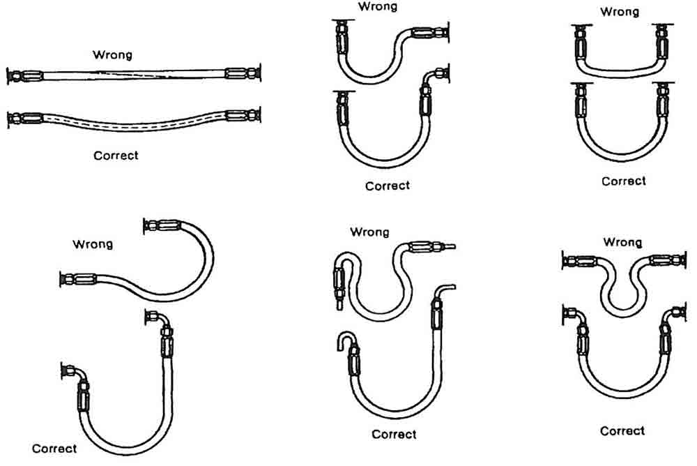
Figure 9: Hydraulic hose pipe bending methods 
Table 1: Performance chart of air oil cooler (Source: Seim, Italy) 
Table 2: A performance chart of a refrigerated oil cooler (Source: Seim, Italy)
References
[1] P. Mehta, “Hydraulic Elevators: Busting the Myth,” EW India, 2nd Quarter 2010.
[2] P. Mehta, “Hydraulic Elevators – Configuring the Power Unit,” EW, December 2010.
[3] F. Celik and M. Kucur, “Importance of Thermal Balance for Hydraulic Elevators,” Elevator Technology 18: Proceedings of Elevcon 2010.
Get more of Elevator World. Sign up for our free e-newsletter.


