Integrated Control Solution Provides Many Advantages
Sep 1, 2013

Elevator control technology has come a long way since the days of the earliest Ward Leonard control system. The lift engineer’s work has only become more complicated as attention is given to every single detail of design, lift travel, safety and commissioning. While simplification and ease of use must drive any technical advancement, both laymen and learners are often confused when dealing with new control technologies.
While the field engineer has been dealing with separate wirings and commissioning procedures for both an individual variable-frequency drive (VFD) and controller, the time has come for our industry to embrace the integrated elevator controller (IEC). Combining the features of a VFD and lift controller, it provides a cost-effective technological advancement that caters to the needs of both the end user and field engineer, and offers enhanced safety.
Evolution of the Elevator Controller
- Ward Leonard: the earliest elevator controller can be traced back to the long-accepted Ward-Leonard system. It used a motor-generator set. The output of the generator is given to the DC motor, the control of which is to be established.
- PLC and AC inverter: programmable-logic controllers (PLCs) were introduced in the late 1960s. The primary reason for designing such devices was to eliminate the large cost involved in replacing complicated relay-based control systems. The availability of programmable input and output also proved to be a good change. Even today, there are OEMs that use this control technology for their hydraulic lifts. With smaller size, better diagnostics and easy programming, PLCs set the trend for the modern elevator controller.
- Elevator controller and AC inverter: this system represents the present-day trend. With the need for elevator-specific functions and controls, customized microcontrollers for specific elevators emerged. Retention of the compactness and easy programming from the PLC made this controller a successful innovation.
- Integrated solution: with rapid advancements in silicon technology, this was simply a change for which the time had come. Integrating the elevator controller and VFD led to many advantages, including reduced size, cost, wiring, commissioning and time. The advent of the integrated solution meant that highly advanced safety standards, improved ride quality and better commissioning experience could be guaranteed.
Evolution of the Modern Elevator Machine
Rapid development of electrical machines was the catalyst for progress in elevator-control technology. DC machines played an important part in the advent of control technology in the Ward-Leonard system. After the era of DC machines, induction-motor technology almost gained a monopoly in the elevator industry.
The machines were mostly geared, as the motor torque would be transferred on a gear system, which would mobilize the lift. The control setup was not preventive, because of the lack of motor feedback. This system was called the “open-loop geared system.” With the advent of feedback components like encoders and resolvers, safety and monitoring of elevator technology were highly improved. This system was called the “closed-loop/geared-machine” system. Both are still popular.
During the last decade, permanent-magnet synchronous machines played a major role in development. Along with advanced SinCos encoders, synchronous machines formed a new system with a promising future. The green-minded, safety-conscious era welcomed machines that consumed 40% less power than conventional motors. Known as gearless machines, they did not require a set of gears to mobilize a lift.
Traditional Elevator Control
Today, control of elevators is through an AC inverter/VFD and a dedicated elevator controller. A brief explanation of the components is given below.
AC Inverter
The variable-frequency drive controller is a solid-state conversion system consisting of three distinct subsystems: a rectifier bridge converter, a DC link and an inverter. Voltage-source inverter (VSI) drives are, by far, the most common type of drives. The most basic rectifier converter for the VSI drive is configured as a three-phase, six-pulse and full-wave diode bridge. In a VSI drive, the DC link consists of a capacitor that smoothes out the converter’s DC output ripple and provides a stiff input to the inverter. This filtered DC voltage is converted to quasi-sinusoidal AC voltage output using the inverter’s active switching elements. VSI drives provide higher power factor and lower harmonic distortion.
Lift Controller
A lift controller is a single integrated circuit containing a processor core, memory and programmable lift-specific input/output (I/O) peripherals, logic units for elevator functions like braking, automatic rescue operation, etc. A good elevator controller must also have a communication module that gives instructions to and receives information from the AC inverter.
Independent Elevator Controller
VVVF drives and lift controllers have to support lift-specific I/O functions, such as direction buttons, floor buttons, car inputs, floor and car display I/Os, emergency stops, car status reports and voice annunciation. With both devices constantly trying to communicate with each other and the remaining I/Os, one can picture a highly complex network of instructions and information being exchanged throughout the system.
While trying to generate the profiles, the controller must maintain and keep track of the brake logic with the motor and remote database logic, while simultaneously conveying the same information to the VFD. In the traditional system:
- Up to 10 numbers of additional digital and analog I/O interface is required between the elevator controller and VVVF AC inverter. Likewise, this holds true for the encoder signal. A traditional system requires a dual feed to both the elevator controller and AC inverter. The AC inverter neither knows the current position of the elevator car, nor where it is going next.
- In the event of malfunction detection, the elevator controller has to apply the emergency brake to prevent damage.
- There are basically two sets of parameter entries: one set for inverter, and one for controller. This increases the commissioning and fine-tuning time and effort.
- With the drive and controller generating separate ramp profiles, there are many chances of the ramp profiles becoming conflicted.
The ideal solution to solve this complication is to merge the two technologies. With the integrated solution, we believe and can prove that the whole elevator experience has only gotten better.
Integrated Solution
The integrated solution for elevator control is simply the embedding of the VFD and elevator-controller technologies into a single unit. It easily solves the aforementioned problems. Further, it has the following advantages over the traditional control system:
- Safety: the integrated solution continuously monitors and updates the position of the elevator car and manages the safety functions for every few microseconds. It has full information about car position, distance to end limits, present speed, nearest door zone, etc., and can respond in a secure and timely manner, which ensures a smooth stop without sudden braking.
- Seamless software: it offers a single programming keypad for both the elevator controller and VVVF drive, eliminating the need for two programming tools, manuals and individual training. Diagnostics accurately point to the exact problem, which reduces troubleshooting time.
- Smooth ride comfort: the integrated solution provides optimum travel speed with minimum travel time and maximum comfort for different floor heights with direct-to-floor landing (distance control). Smart management of the optimum Sramp profile generated is shared
directly with the VVVF AC inverter microprocessor without noise interference or dual-ramp conflict. - Cost savings: reduction in components and wiring automatically reduces the net cost of the control system. Indirectly, reduction in commissioning and troubleshooting time also lowers cost.
- Space savings: panel space is optimized.
- Simplification: setting up and fine tuning elevator ride comfort is performed with a common set of parameters in easily understood elevator terms (“m/s,” “kg,” etc.). In the traditional system, there are two sets of programming parameters: one for the AC inverter and another for the elevator controller.
The IEC eliminates the need for close matching of parameter settings of the elevator controller and VVVF AC inverter, along with brake open/close time-delay adjustments, which are vital for achieving reasonable ride comfort.
Conclusion
The IEC is not a novel idea, but a well-proven concept. Of the 450,000 lifts produced in 2012 in China alone, more than 360,000 sets included IECs. This proves the acceptance of the integrated solution. It is only a matter of time before the rest of the world embraces this innovation.

Figure 1: An IEC 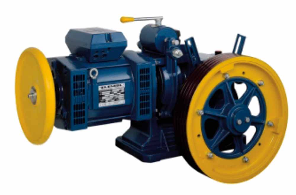
Figure 2: An open-loop induction machine (photo source – Montanari) 
Figure 3: Closed-loop induction machine with incremental encoder (photo source – Montanari) 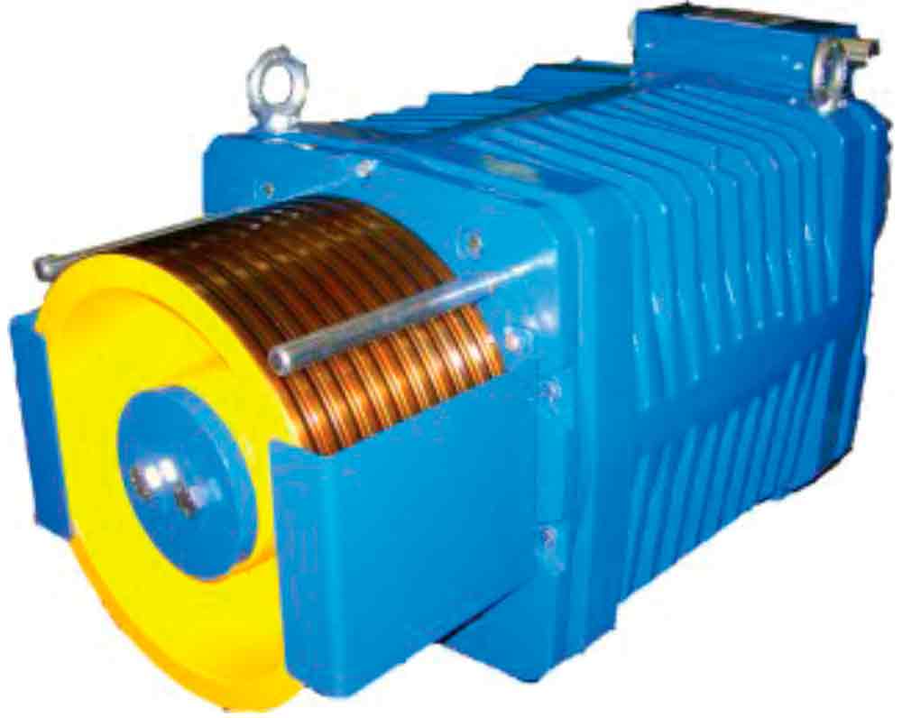
Figure 4: Gearless synchronous machine (photo source – Montanari) 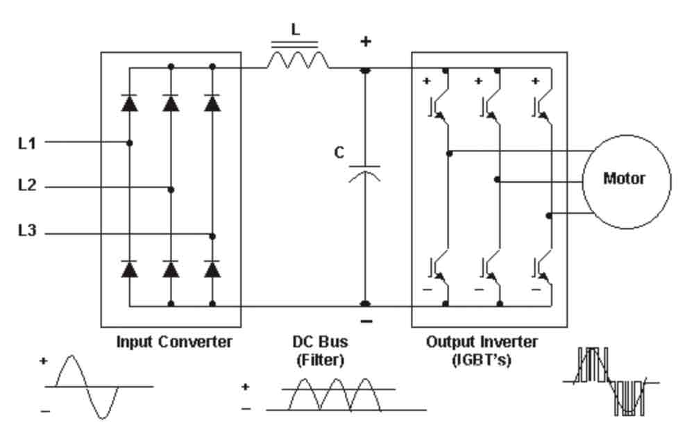
Figure 6: Block diagram of a VVVF drive 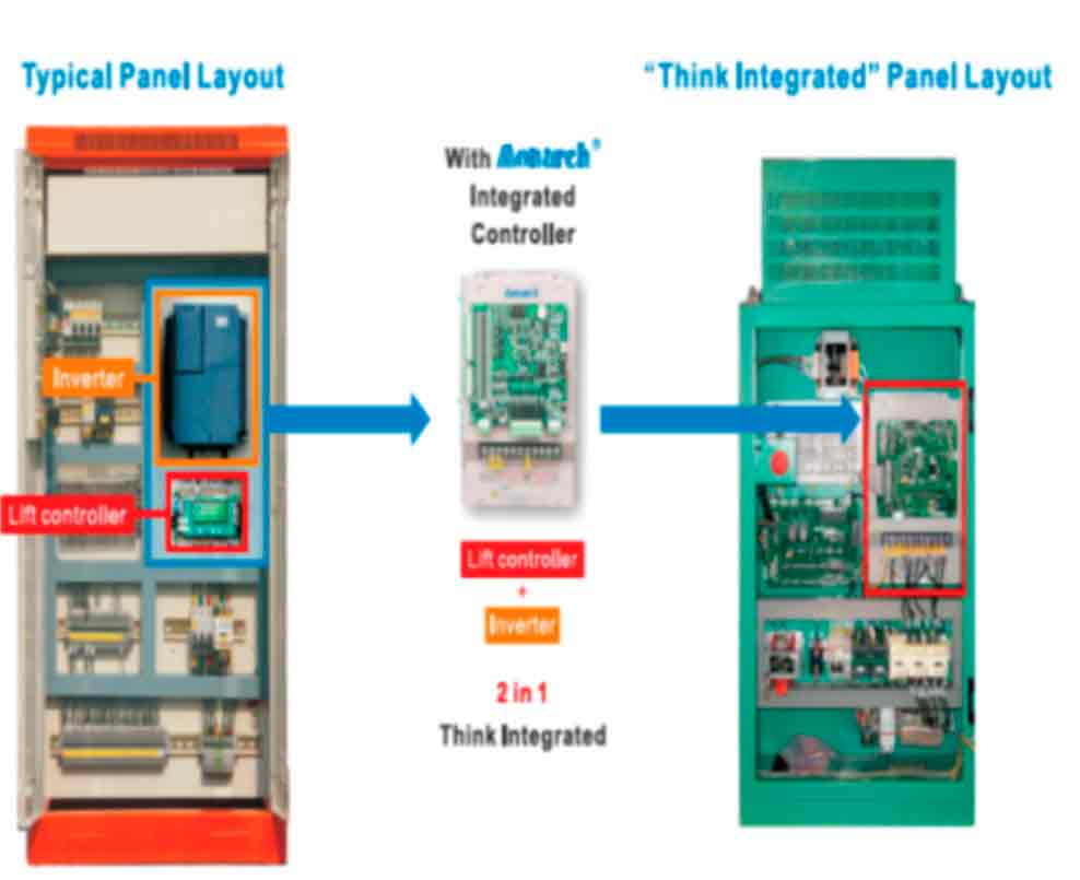
Figure 7: IEC panel layout 
Figure 8: Automatic generation of S-ramp profiles
Get more of Elevator World. Sign up for our free e-newsletter.