Intelligent Transit in Modern Buildings
May 1, 2013
Modern buildings impact the balance of an urban environment and represent one of the most important mediums in drawing public attention and epitomizing citizens’ pride in their cities. They represent a significant building typology that continues to grow all over the world.
Once the basic form and shape of buildings are determined, the most painstaking part is to cater to allied services, which can help keep the modern building up and running at all times. As is the case with most spheres of modern social life, better planning and technology are vastly improving results from building planners. People’s movement management becomes the key to be able to extract the most from a building’s facilities, and if this can be done in an intelligent, energy–efficient manner, half the battle is already won.
Elevators made it possible for cities to expand upward and become global engines of economic growth and progress. Today’s global trends are creating new opportunities and challenges for our industry. This growth can largely be credited to the following factors.
Urbanization
More than 50% of the world’s population now lives in cities, and migration is accelerating this trend further. In China alone, more than 12 million people move from the countryside to urban areas each year. Elevators will continue to play a greater role in urban development, because the emerging model of sustainable urban living has to be vertically oriented with high-density cities connected by public transportation. We are already witnessing this in emerging countries, especially in Asia. Here, traditional single-purpose buildings next to each other along a street are giving way to more complex multipurpose structures linked by public-transportation systems located underground or overhead. While India continues to trail even the other developing nations in this regard, plans to catch up on this trend are afoot.
Demographics
Urbanization is accompanied by related demographic trends, such as the increase of people of household-formation age in economies such as India, Latin America, Turkey, the Arab world and China. In India, for example, the number of urban middle-class households is expected to grow from less than 10 million currently to more than 87 million by 2025. This rising consumer market will drive the need for more and improved residential living space, all of which will lead to the derived demand for better-elevatored structures.
Per-Capita Income Growth
The emergence of a middle class in much of the developing world, especially China and India, is creating new consumer societies looking for new and improved residential living space. In many cities, congested roads, inadequate facilities and undeveloped or fragmented shopping areas are already giving way to new public-transportation systems, airports, hospitals, shopping malls and other modern urban infrastructure.
Energy Efficiency
Wide-reaching political and societal changes are projected to accompany these developments. One is the green movement, which is transforming the construction and automobile industries, and increasingly exerting pressure on building construction and its allied agencies, chief amongst them elevator installation. This is especially relevant in terms of how elevators contribute to the energy efficiency of a building.
Safety and Comfort
Safety and comfort have always been vital, but they are becoming even more so because we are increasingly dealing with structures and challenges of unprecedented scales. Today, buildings more than 500 m high are increasingly part of the urban landscape, which means we must provide safe, comfortable journeys at speeds in excess of 10 mps and allow for pressure changes that would literally make riders’ ears pop. Then, there is traffic management, security and access control, which must be convenient, fast and secure.
Innovation – A Necessity
To meet any/all of these growth challenges, we have to continuously innovate. For instance, Schindler has made strides in traffic management and access control. This trend must be continued, along with solutions to improve reliability and energy efficiency. We must also look hard at how we carry out the service business in light of environmental considerations.
Traffic Management
HC5%
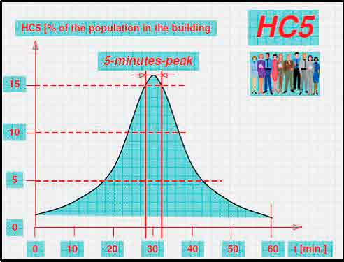
5-min. handling capacity (HC5%) is the total number of passengers an elevator system can transport within a period of 5 min. during up-peak traffic (Figure 1). The value is expressed as a percentage of the population on the upper floors.
THAQ
Theoretical traveling time (THAQ) is traveling time for the entire height of a building without taking into account time lost by acceleration and deceleration (Figure 2). It is recommended this value be 20 s. for top requirements, 25 s. for medium requirements and 32 s. for basic requirements.
RTT
Roundtrip time (RTT) is the time between two starts of the same elevator from the main entrance (Figure 3). It is evaluated by mathematical formulas and a predefined table for the number of expected stops and averaged reversal floor.
Interval
The interval is the average time lag between successive departures of cars from the main stop (Figure 4). It is recommended this be 25 s. for top requirements, 32 s. for medium requirements and 40 s. for basic requirements.
Method of Traffic Analysis
A traffic analysis should cover a variety of important traffic situations, especially when planning new buildings. Reported values should be as reliable and comparable as possible. However, performance values depend on the methods of the traffic analysis and basic traffic assumptions, for which the following preliminary inputs are necessary:
- Purpose of building, including purposed zones (e.g., area designations, such as parking, restaurant, health club)
- Building elevation, including exact interfloor distance
- Building occupancy plan and/or floor area (e.g., number of hotel rooms, residential flats per floor and square footage of office area tenanted)
Simulation Versus Calculation Methods
In simulation methods, a real passenger flow is being replaced by a virtual one created with the help of a random generator and loaded into the same control algorithm as used in a real elevator controller. Thus, the results can be measured under different traffic conditions and reflect the expected reality. In contrast, calculation methods are based on formulas that only cover a very limited range of traffic situations (usually, only up-peak traffic). The formulas reflect theoretical assumptions, rather than a realistic behavior of elevator groups, and results are usually too optimistic. Therefore, calculation results should not be compared with simulation results.
The traffic flow in a building changes constantly; no two days are the same. As a rule, traffic depends on many factors (such as location of building, tenant structure, etc.) and may vary considerably during building operation. A traffic analysis should take such factors into consideration and try as far as possible to cover future traffic situations.
In a complex building, a single traffic assumption is not sufficient (e.g., it is not sufficient to apply a traffic pattern measured in an existing building to the design of a new building). In particular, the limits of elevator handling capacity cannot be found by such an examination. Predictions of the range of handling capacity of an elevator group can only be made by simulating a wide range of traffic situations. A benchmark method applies a reference traffic situation from low to very high traffic intensity; the limits of the elevators’ handling capacity can be detected by this. Schindler uses a benchmark method that gives a neutral system assessment.
Elevator Control Systems and Traffic Management
Typical architecture of an elevator control system is illustrated in Figure 7. The control boards of an elevator group are usually situated in a machine room. There can be one or several group controls in an elevator group. One of the group controls is the master, which delivers the hall calls to the elevators, and the other group controls are backups. Other functions inside the car (e.g., registering and canceling of car calls, door control and measurement of the car load) are handled by the elevator control. Modern elevator controls provide built-in elevator-monitoring devices or remote building-monitoring systems to follow the elevator traffic. Typical control software for an elevator component includes an operating system; task-scheduling programs; input, output and communication programs; and programs for controlling and optimizing component function.
The group control allocates hall calls to the most suitable elevators by optimizing the cost function. The most usual optimization target in an elevator control is to minimize hall-call times. It has been found, however, that by optimizing passenger journey times, the number of elevator stops is reduced, which increases handling capacity. The same traffic can be handled with fewer elevators than would be needed for a conventional system. In Schindler’s Miconic 10™ control system, special keypads at the landing floors are used. Passengers can input their destinations at the landing floors, so no car calls inside the elevators are needed. With normal up-and-down hall call buttons, passenger arrival floors, times and destination floors cannot be determined.
History/Principles of Group Control
The first elevators were operated by simple mechanical devices, such as “hand-rope” control. A passenger could call an elevator by operating a rope on both sides of the car. Since the shafts were not fully closed, the operation of elevators was quite unsafe. A primitive form of elevator control in a single car was based on an attendant-operated electrical car switch. Using the switch, the attendant could manually drive the car up or down and decide at which floors to stop. Elevator efficiency and safety were increased with signaling devices at landings. Push buttons were introduced in the 1920s to give the attendant information on traffic demand, and elevator shafts became closed. When the registered calls are memorized, the elevator can pick several hall calls during the up or down trip. If there is only one call button at each floor, the calls can either be arranged in a time queue according to the order registered, or served collectively.
In the interconnected-queue-selective control system, hall calls are picked one at a time from the time queue so the oldest call is served first. This type of control is used, for instance, in hospitals, where bed calls are served individually. In collective control, the car stops in floor sequence at each hall call. The interconnected-down-collective control system is often used in buildings where traffic is mostly two way between the ground level and the upper floors. This kind of traffic occurs, for example, in residential buildings. The elevator collects the hall calls during the down trip (i.e., serves the calls in sequence), always stopping at the nearest call floor.
In high-rise buildings, hall-call buttons for both up and down directions were adapted. The most common call-allocation principle, especially in old relay controls, is the interconnected-full-collective control system. With two buttons at each floor, an elevator can pick the nearest hall call in front of the car in its direction of travel. The car calls given inside the elevator are always served in sequential order. After serving all the calls in the travel direction, the car moves to the furthest hall call in the opposite direction, where it reverses its direction.
Elevator-group efficiency was improved with a common central logic, the group control. The hall calls could be shared between several elevators where a common hall-call button exists at every floor. The group control chooses the best elevator from a group of elevator cars to serve a given hall call. Group control also dispatches cars to floors for other reasons than hall calls, such as for parking or if more than one elevator is needed at a busy floor. Elevators can be disconnected from the group for special service modes, such as emergency service, Firefighters’ Service or VIP service. A disconnected elevator operates independently of the other elevators.
One drawback of the collective control principle is the bunching of elevators. During heavy traffic, there are many hall calls to serve, and the elevators have a tendency to move side by side (i.e., they start to bunch). This happens because elevators always stop at the nearest call and bypass hall calls only when fully loaded. One of the early methods of preventing the bunching of elevators was to adopt a bus-type schedule by dispatching cars from the lobby at specific intervals. Elevators were delayed at the lobby for a certain time before they were sent to the upper floors. However, by delaying elevators at the lobby, part of the handling capacity was lost.
In the 1970s, collective control was first adapted to electronic controls. This improved collective controls by giving priorities for the long or timed-out hall calls. Hall calls that had been on for a short time were bypassed in favor of faster service for the timed-out calls. To some extent, the elevators were kept apart from each other with this control. Peak traffic situations were handled with separate operation modes. In up-peak operation modes, such as next car up, dispatching intervals, zoning of floors and, later, a channeling option were used.
The allocation principles of relay and electronic controls were brought to microprocessor controls in the early 1980s. Hall calls were still prioritized according to the call service times, and the hall-call times were forecast with mathematical calculations. When it was found a hall call would become long with the normal service order, a car would bypass some hall calls to provide faster service to this call before it became long. When bypassing other hall calls, it was checked whether the bypassed calls could be served by other cars within an acceptable timeframe.
One important feature in the modern group supervisory controls is the time when hall calls are finally reserved to the cars. The reservation moment can be seen in the signalization at the landing-call floor. As soon as the hall call is finally designated to a car, an arrow above the car-door opening is illuminated. Simultaneously, an audible gong signal is given to inform the passenger which car is going to serve the given hall call. The final reservation must be stable so the passenger is not misled. For optimization, the reservation is often made at the latest possible moment (i.e., when the elevator starts to decelerate to the hall-call floor). The other extreme is to allocate hall calls to an elevator immediately after the hall call has been given. This shortens the psychological waiting time of the passengers. Passengers have more time to gather around the arriving elevator, which shortens the loading time. When the hall calls are allocated at an early stage, future traffic events change the situation so the early reservations are not as optimal as if the allocation were made later. In the course of the fast development of microprocessor technology, call-allocation algorithms have become more sophisticated, and building traffic is measured and learned in statistical forecasts.
The Schindler 7000 traffic-management system is based on the following principle of bringing passengers to their destinations faster with less crowding and more comfort than a conventional elevator system (Figures 8-10). Through the embedded Miconic 10 destination-control system (DCS), the system’s software drives a logic program that systematically optimizes the elevator traffic flow. It uses an algorithm to manage the complexities of traffic patterns as they change through the day.
Example
In an example of a simplified classic up-peak situation, 24 people call elevators to travel from the lobby to various different floors over a period of a few seconds. With conventional control, the first 10 people cram themselves into the first available car. The next eight fill the second, and the few remaining occupy the other cars. This random passenger behavior means every car makes multiple stops, so journey times are lengthened, and most passengers suffer overcrowding. The Schindler 7000 system, conversely, limits a maximum comfortable car load at six persons and has recorded that floors four and five have the highest density of calls in up-peak traffic. The system directs the six passengers traveling to each of the two busy floors to individually assigned cars and optimally distributes the others. As a result, it ensures all the passengers experience a fast one- or two-stop ride, no one suffers overcrowding, and transit time is shorter and more comfortable.
DCS Versus “Hybrid” Control Logic
There are different control functions in service, which should advance the traffic peaks in the morning, during lunchtime and in the evening. These control functions are often promoted with different and partially contradictory arguments. The following comparison will look at hybrid control (up-peak boosters) versus DCS. All aspects, including performance, costs and user friendliness, should be considered.
Up-Peak Boosters
Up-peak boosters are a mix between conventional control and a DCS. User interfaces with 10 digits in the lobby and a conventional operation panel with up and down buttons in the other floors use the DCS concept in the main lobby only and assign elevators to the users according the indicated destination. The term “up-peak boosters” is assigned because the DCS concept is used only for up-peak traffic.
In the up-peak, handling capacity can be increased (i.e., boosted) by reducing the number of stops during the up trip. The total time, including waiting time and ride time inside the car and journey time, becomes shorter with zoning. The elevator group can, for instance, be zoned so half the elevators serve the lower part of the building, and the other half serves the upper part. At the entrance floor, car calls are accepted only to served floors of the car. The served floors of each car are indicated above the landing doors. The fewer floors an elevator has to serve during the up trip, the shorter the RTT becomes. Also, the shorter the RTT, the more up-peak handling capacity increases. The served floors of an elevator group can be split into as many sectors as there are elevators in the group. The service interval and waiting times become longer, since a waiting passenger cannot enter any elevator, but has to wait for a specific car.
DCS
In a DCS, the system insists on each floor – the entering of the destination floor. Here, passengers with the same destination floor are gathered in the same car. The number of stops during the up trip is reduced, and handling capacity increases. Passengers give the destination call at the landing floor, and the control system indicates to the passenger which car to enter. The DCS implements the concept of the up-peak booster in all traffic situations, giving it flexibility and applicability.
| Characteristic | Schindler’s DCS | Up-Peak Boosters | Remarks (Related to Up-Peak Boosters) |
| Building Types | Various types of buildings, independent of the traffic situation | Mostly single-tenant office buildings | Application is limited to traffic situations where many people are entering the building at the same time. |
| Performance/Handling Capacity | High | May not be more advantageous than conventional control | Depending on the configuration, the whole system can be disturbed by redundant car calls. |
| User Interface | Consistent | Varies depending on floor and time | The elevator doesn’t have an uniform operation mode. |
| Flexibility | Adaptable to all traffic situations | Just applicable for up-peak traffic | Inflexible to changing patterns |
| User Error | Improbable | High likelihood, because of the additional COP | If the functioning of the COP is not limited, wrong or redundant inputs may be given |
| Scope | General traffic | Up-peak traffic | Limited scope |
| Robustness in Practice | Proven by experience; highest number of functional units worldwide (more than 6,000) | Depends on users’ cooperation; very few installations | Lack of cooperation can limit the performance of the whole up-peak system. |
| Traffic Optimization | Always | During up-peak traffic | Limited in scope |
| Security/Access Control | Yes (whole building) | Only possible for the floors with 10-digit terminals (lobby) or via COP | Access control cannot be resolved uniformly for hybrid control systems |
| Transit Management | Yes | Does not make sense with up-peak booster systems | Not future ready |
Main Disadvantage of the Hybrid System
Since the car-operating panel is active as soon as the car leaves the main floor, passengers can key in additional floors. This will lead to a situation where users will just enter the lift cars available at the main floor, then key in their destination floor after the lift has started to move. This would totally negate DCS’ main advantage (i.e., shorter time to destination because of lesser stops).
Conclusion
The application range for up-peak booster systems is limited to the building and elevator type. It makes sense more for single-deck elevators and single-tenant office buildings. It also limits the flexibility of the system and the application of the building. Lerch Bates Inc. recommends using full destination hall-call systems in the following situations:
- When probable stops above the main dispatch lobby include six or more landings served by three or more elevators
- When evaluation of traditional two-button systems, as measured by traditional average interval and handling capacity, yield marginal results for the building type
- When the building contains multiple loading lobbies or an intermediate destination floor (auditorium, cafeteria, theater, etc.) requiring special consideration
- When the average time to destination results exceed 60 s. with a conventional two-button control system
Personalized Transit
Schindler’s Personal Occupant Requirement Terminal (PORT) makes a networked and highly personalized environment that recognizes occupants and responds to them individually (ELEVATOR WORLD, January 2011). The technology manifests itself to aid a building’s overall movement management: ingress, egress and movement within the building (Figure 12). It can regulate this movement and, in doing so, provide either the primary or secondary line of defense for building security through access control. This can effectively reduce or even eliminate the need for personnel or other systems to verify occupants’ or visitors’ access rights.
The system can also be programmed to take account of user preferences. Hence, a resident of a building may choose to always travel alone in an elevator when going to his or her office or apartment, in which case, the car will not stop for anyone else during that particular journey. The ride can be fully customized to the user’s preference by personalizing in-car entertainment, lighting, etc. Because its interfaces are equipped with both visual and verbal instructions, PORT can further accessibility: occupants with a visual impairment, for instance, can choose to be assigned routes equipped with tactile indicators, while a wheelchair user can opt to always use a more spacious elevator or travel alone.
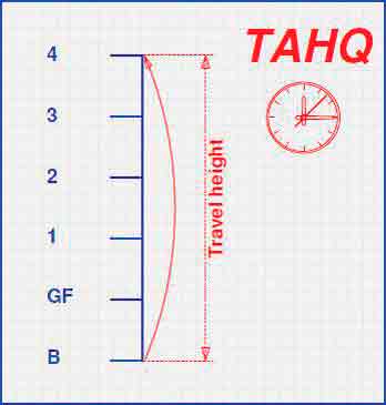
Figure 2: This determines the rated speed. 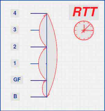
Figure 3 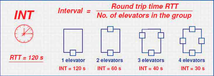
Figure 4: This determines the number of elevators. 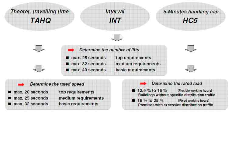
Figure 5: A summary of the interpretation of traffic-calculation parameters 
Figure 6: A summary of destination time. The current equation for calculation destination time is WT + BT + TT + ET, and the new one is WT + BT + TT. 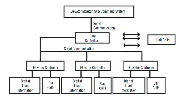
Figure 7: Elevator group control 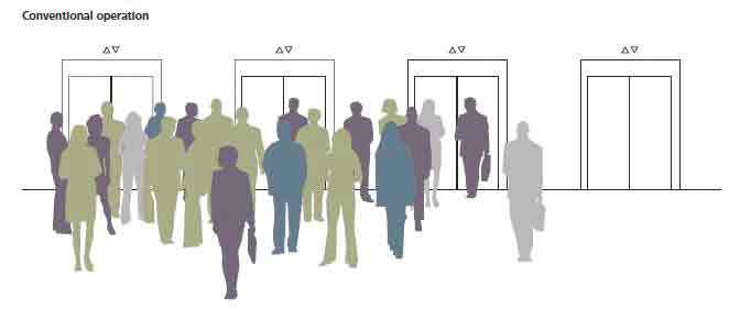
Figure 8: A typical lobby with a conventionally operated system 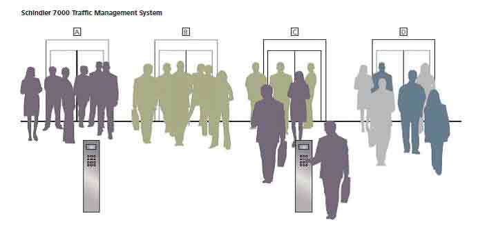
Figure 9: A typical lobby using the Schindler 7000 traffic-management system 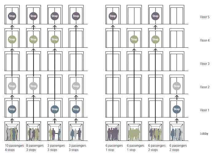
Figure 10: (l-r) Conventional control versus that of the Schindler 7000 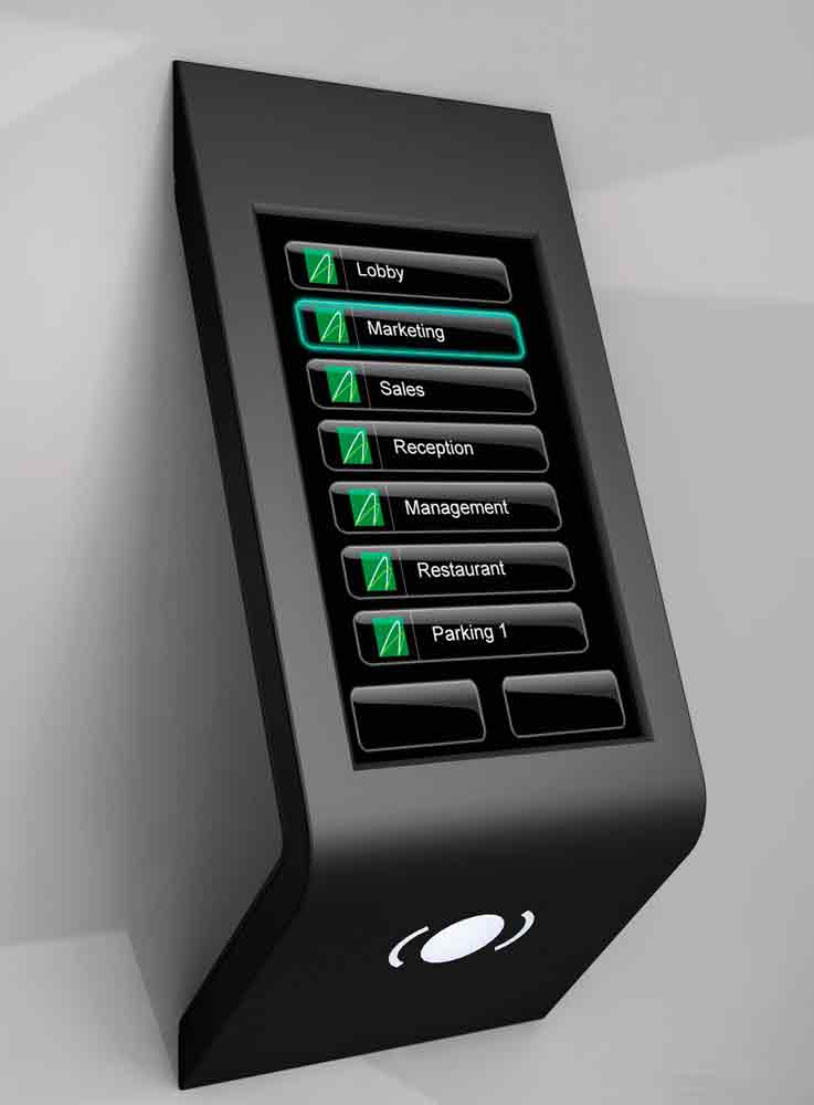
Figure 11: The Schindler PORT interface 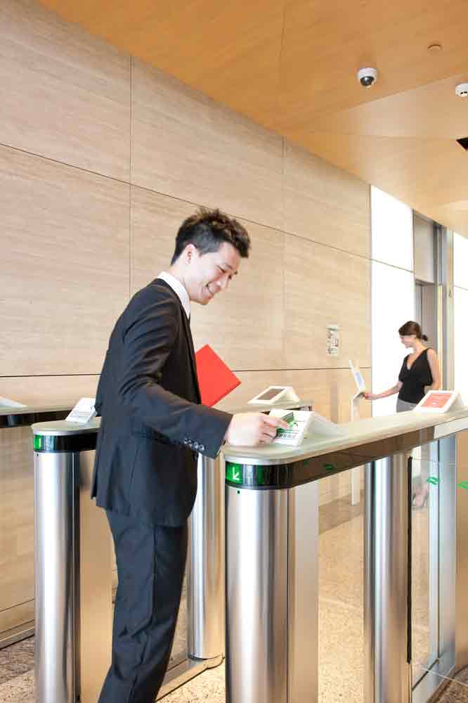
Get more of Elevator World. Sign up for our free e-newsletter.

