
A review of the protective measures of the requirement in lifts
Abstract
Two major earthquakes happened in Türkiye on February 6, 2023. The levels of the earthquakes were 7.8 Mw and 7.5 Mw, and they were very destructive. More than 40,000 people died, and cities, towns and villages were destroyed completely.
I visited the earthquake zone just after the earthquakes and saw that most of the buildings were completely collapsed. But what happened to the lifts in buildings that were standing? In most situations, counterweight frames separated from guide rails, suspension ropes separated from sheaves and traveling cables were damaged.
The content of this paper details the protective measures of the EN 81-77 requirement in lifts. What is design acceleration (ad), and how is it calculated? We will review the information from EN 1998-1 that is required for calculation of ad. How seismic zones are defined based on ad will be seen. Protective measures for elevators in each seismic zone will be reviewed.
1. Introduction
Earthquakes are a serious natural disaster for many countries and cities around the world such as the west coast of the U.S. and Canada, Italy, Iceland, the Balkans, Türkiye, the east coast of the Mediterranean Sea, Iran, Pakistan, Central Asia, Southeast Asia, the whole of Central America and the west coast of South America. Approximately 1.6 billion people around the world live in areas at high risk of earthquakes.
Over hundreds of years, humanity has developed measures to build structures to withstand earthquakes. The vertical-transportation (VT) industry has also developed measures to keep elevators and escalators safe in case of an earthquake. Mainly, European, North American and Japanese codes are leading the effort to improve the safety of elevators during an earthquake.
EN 81-77 is the European code and describes safety rules and requirements for passenger and goods lifts to withstand seismic conditions in compliance with EN 1998-1. EN 81-77 aims to avoid loss of life, reduce injuries, prevent entrapment in the car, prevent damage and environmental problems and reduce the number of lifts that stop working after an earthquake.

2. Design Acceleration
Design acceleration (ad) is the horizontal acceleration arising from seismic events, and it is used to calculate forces acting on lifts systems. It is a function of ground acceleration, soil behavior, importance of nonstructural elements and some other parameters. Elevators are nonstructural elements, according to EN 1998-1. EN 1998-1 is Eurocode8 and regards the design of structures for earthquake resistance. The formula of ad is below:
Sa in the formula is the seismic coefficient that is applicable for nonstructural elements and is a number that is nondimensional.
ga is importance factor. This factor is 1 for lifts in residential and office buildings. If lifts are in hospitals or will be used for special reasons like emergency services, in this case, the value shall be increased according to EN 1998-1. ga is nondimensional. Importance factor can be defined by national authorities, as well as based on seismic behaviors in the country.
qa is the behavior factor of the element. It is nondimensional and should be equal to 2 for lifts.
Sa needs to be calculated as explained below:
a is nondimensional and is the ratio of design ground acceleration (ag) on Type A ground to gravity (g).
α=ag/g
ag= gl.agR
ag: Design ground acceleration
g1: Importance factor
agR: Reference peak ground acceleration on type A ground
g1 importance factor is defined based on importance classes of buildings, and it is between 0.8–1.4. Importance classes of buildings are related to the building types as defined below:
Class – I (g1=0.8): Buildings have minor importance for public safety like agricultural buildings, etc.
Class – II (g1=1.0): Ordinary buildings, not belonging in the other categories.
Class – III (g1=1.2): Buildings whose seismic resistance is of importance in view of the consequences associated with a collapse, e.g., schools, assembly halls, cultural institutions, etc.
Class – IV (g1=1.4): Buildings whose integrity during earthquakes is of vital importance for civil protection, e.g., hospitals, fire stations, power plants, etc.
agR, is the reference peak ground acceleration on type A ground, agR, for use in a country or parts of the country, may be derived from zonation maps that can be found in related national annexes.
S in the formula is soil factor according to EN 1998-1, and it is nondimensional. S is 1.0 for type A ground, 1.2 for type B, 1.15 for type C, 1.35 for type D and 1.4 for type E. We recommend you always get the ground type of the project from the static designer of the project.
Ta is the fundamental vibration period of a nonstructural element, and it is in seconds. If the lift does not affect the fundamental vibration of building, Ta is 0.
T1 is the fundamental vibration period, and it is in seconds.
z is the height of the highest part of the lift above the foundation or rigid basement. It is in meters.
H is the height of the building above ground level, and it is in meters.
3. Seismic Lift Categories
The seismic category of a lift is determined according to ad.
If 1 < ad ≤ 2.5, the lift’s seismic category is 1;
2.5 < ad ≤ 4, the lift’s seismic category is 2;
ad4, the lift’s seismic category is 3>.
4. Requirements for Category 1
Suspension ropes, overspeed governor ropes, traveling cables, compensation ropes and chains may sway during an earthquake in the lift shaft and will get entangled with fixed equipment and snag points. These snag points will be created by brackets, sills and devices fixed in the lift shaft. Snag points need to be protected if the shaft height is above 20 m.
The following protection measures need to be taken when the traveling height is between 20–60 m:
- If any snag point in the shaft like brackets, sills etc., is closer than 900 mm from the loop of the traveling cable, protection with a wire between snag points is required.
- Wire protection between brackets and similar snags is required during the whole travel height for compensation ropes, chains and CWT overspeed governor ropes if snag points are closer than 750 mm to the related equipment. This is required during the whole travel height if the overspeed governor rope is closer than 500 mm and the suspension rope is closer than to any snag point in the shaft.
If the travel height of the lift is more than 60 m, the above-mentioned snag protection measures need to be taken for the whole travel height.
If the building is divided into independent units by expansion joints, the machinery space of the lift should be in the same independent unit of the building.
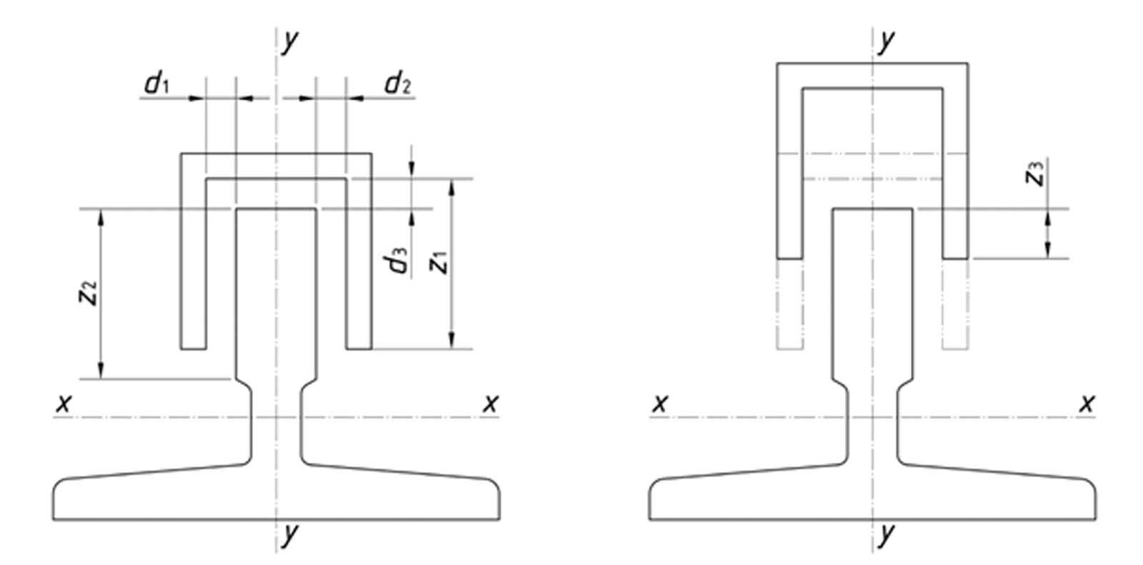
The counterweight should have a retaining device as shown in Figure 2 at the top and bottom of the frame and as close as possible to the guide shoes. d1, d2 and d3 dimensions in the figure should be maximum 5 mm. The retaining device should not cause accidental activation of the safety gear at the counterweight side. The retaining device should be designed and fixed in such a way that z3 in Figure 2 should be minimum 5 mm.
It is required to have retainers for traction and diverting pulleys for traction and compensation ropes. Retainers should be 15° from the entrance and exit of ropes and in every 90° of wrapping of ropes. Retainers should be effective enough in comparison with rope diameters. Retainers are required for chain and sprockets, as well.
Compensation means need to be guided in the pit to prevent swaying and engaging with any snag points.
In the case of hydraulic lifts, lifts should have rupture valves to prevent oil spillage when an earthquake happens.
Guide rails, rail joints and brackets need to withstand the forces that will be created by calculated design acceleration (ad). If there is a retaining device, the device can be used as support for the frame. The deflection produced by ad cannot cause unsafe working of lifts. Door locking devices should remain active, safety gears should work properly and moving parts should not encounter each other. In the case of having a retaining device, at maximum, deflection should not cause less than 5 mm overlapping of the retaining device and blade of the guide rail.
Machines, suspension means, overspeed governors, compensation means and their attachments should be designed and fixed in such a way that forces created by ad should not cause overturning and displacement. In the case of having rigid pipes for hydraulic lifts, each rigid pipe should end with flexible pipe.
All electrical equipment and switches in the lift shaft should withstand forces created by ad.
5. Requirements for Category 2
Requirements for Category 2 lifts are a combination of Category 1 requirements and the following protective measures.
It is required to have a retaining device at the top and bottom side of the car frame. Clearances defined for Category 1 should be maintained for car retaining devices, as well.
Lifts in Categories 2 and 3 should have car door-locking devices. A door-locking device is a safety component and needs to be tested and certified according to EN 81-50.
In case of power failure, the lift should be able to move to the next landing floor in an up or down direction, and entrapment of persons in the cabin should be prevented. The lift should open its door and stay open when it arrives at the landing. If the lift has a semi-automatic door, the door should be unlocked when the lift stops at the landing. If a power failure happens when the lift is at the landing, doors should be open to rescue possible trapped passengers.
6. Requirements for Category 3
Requirements for Category 3 lifts are a combination of Category 1 and 2 requirements and the following protective measures.
If the lift has a counterweight or balancing weight, then the lift should be equipped with a seismic detection system. The detection system should be in the lowest pit level of the lifts in the building or a lower place than the lift shafts. It should be possible to detect three-axis acceleration. Any acceleration equal to or lower than 1 m/s2 should activate the seismic system. Response time should be a maximum of 3 s. The seismic detection system should be checked at least every 24 h, and if it does not work, the lift should be taken out of service. The seismic detection system should have a power supply backup of at least 24 h, and it should only be possible to reset the detection system manually.
When the seismic detection system becomes active, the lift should cancel all hall and car calls and move to the nearest landing at a maximum speed of 0.3 m/s. Cars should not pass the counterweight or balancing weight while moving to the nearest landing level. If a seismic detection system is active when a lift is at the landing, closed doors should be open, and the lift should leave service. If the doors are semi-automatic, they should be unlocked. The seismic mode shall not override any safety device, inspection operation, emergency electrical operation or phase-2 of firefighter mode according to EN 81-72.
7. Conclusion
We tried to explain the calculation of ad and requirements in the lifts if they are in seismic categories according to ad. Our main guide for this paper was the EN 81-77 and EN 1998-1 standards. We strongly recommend calculating ad in any project and taking the needed measurements for the lift based on calculated seismic category.

Get more of Elevator World. Sign up for our free e-newsletter.
![]()


![]()