Maintenance on New Equipment Designs: Electric Driving Machines and Brakes
Apr 1, 2025

The impact of the MRL on these two key elevator features
Value: 1 contact hour (0.1 CEU)
This article is approved for Continuing Education by NAEC for CET®, CAT® and QEI credit and by NAESA International for QEI.
EW Continuing Education is currently approved in the following states: AL, AR, CO, FL, GA, IL, IN, KY, MD, MO, MS, MT, NJ, OK, PA, UT, VA, VT, WA, WI and WV | Canadian Province of BC & ON. Please check for specific course verification of approval at Elevator Books.
Learning Objectives
After reading this article, you should have learned about:
- The function and importance of the electric driving machines and brakes
- New changes and requirements for MRL units
- How to perform maintenance, inspection and testing, and repair and replacement on the electric driving machines
- How to perform maintenance, inspection and testing, and repair and replacement on the brakes
- The cornerstone of elevator safety
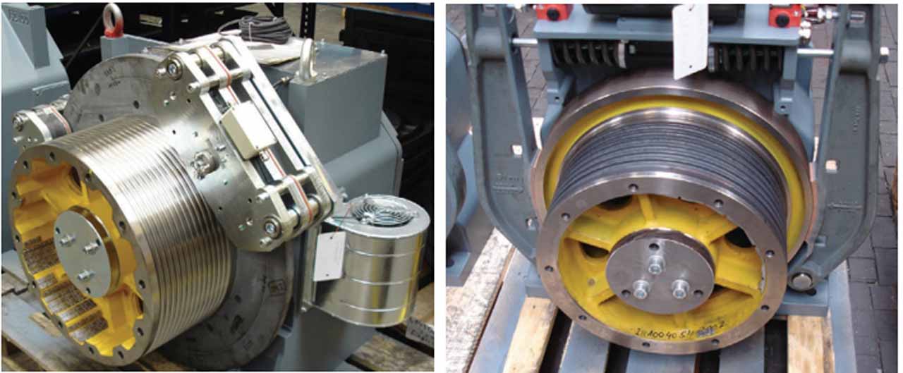
Electric Driving Machines
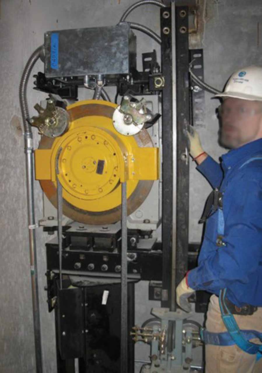
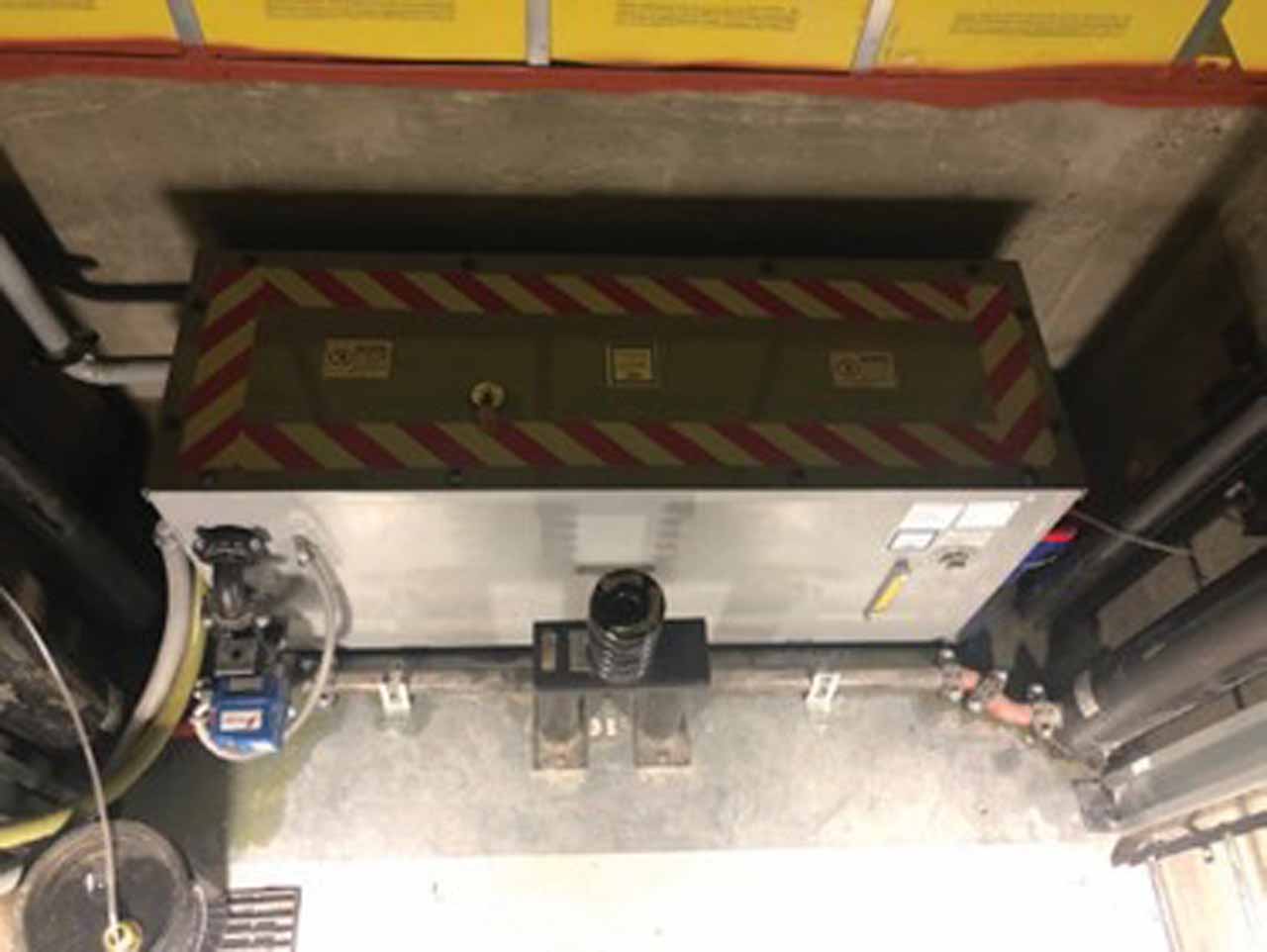
The heart of most machine-room-less (MRL) systems is the location of the driving machine: It not being required to be in a machine room is the reason for the term “machine-room-less.” The express purposes for MRLs are to eliminate the expense of building a machine room on the roof that needs to be heated and cooled and to reduce roof lines that don’t necessarily blend architecturally and don’t require an overhead supporting structure, as most systems are floor loaded. The end result is that the driving machine is located in the hoistway. There are several schemes for specific locations: Some are patent protected, others simply offer novel design and functionality.
In the simplest version, there is a support structure (bedplate and machine beams) sitting atop the hoistway enclosure walls or in pockets in the walls near the top of the hoistway. Other designs include mounting the driving machine on the rails, either on the back or on top of the main guide rails, or on both the main and counterweight guide rails. Other designs rest the driving machine on a spreader beam or wall pocket – behind the main guide rail but not attached to it. Another configuration is the driving machine in the pit area.
From a new risk standpoint, they are not as easy to access. The driving machine used to be in a machine room with a floor around it. Now, depending on the configuration, it may be very difficult to access. The new risks include having to replace or alter the driving machines with their large masses from the top of the car. While these driving machines are smaller and more compact than legacy driving machines, they still can weigh from 340 kg (750 lb) up to 1133 kg (2500 lb); and with little or no overhead to pick up these loads, it is a new and very significant risk. The trade-off in design locations is the reliability that comes with modern electric permanent magnet motors driving gearless machines. If they never have to be replaced, the hazard is not created.
Maintenance
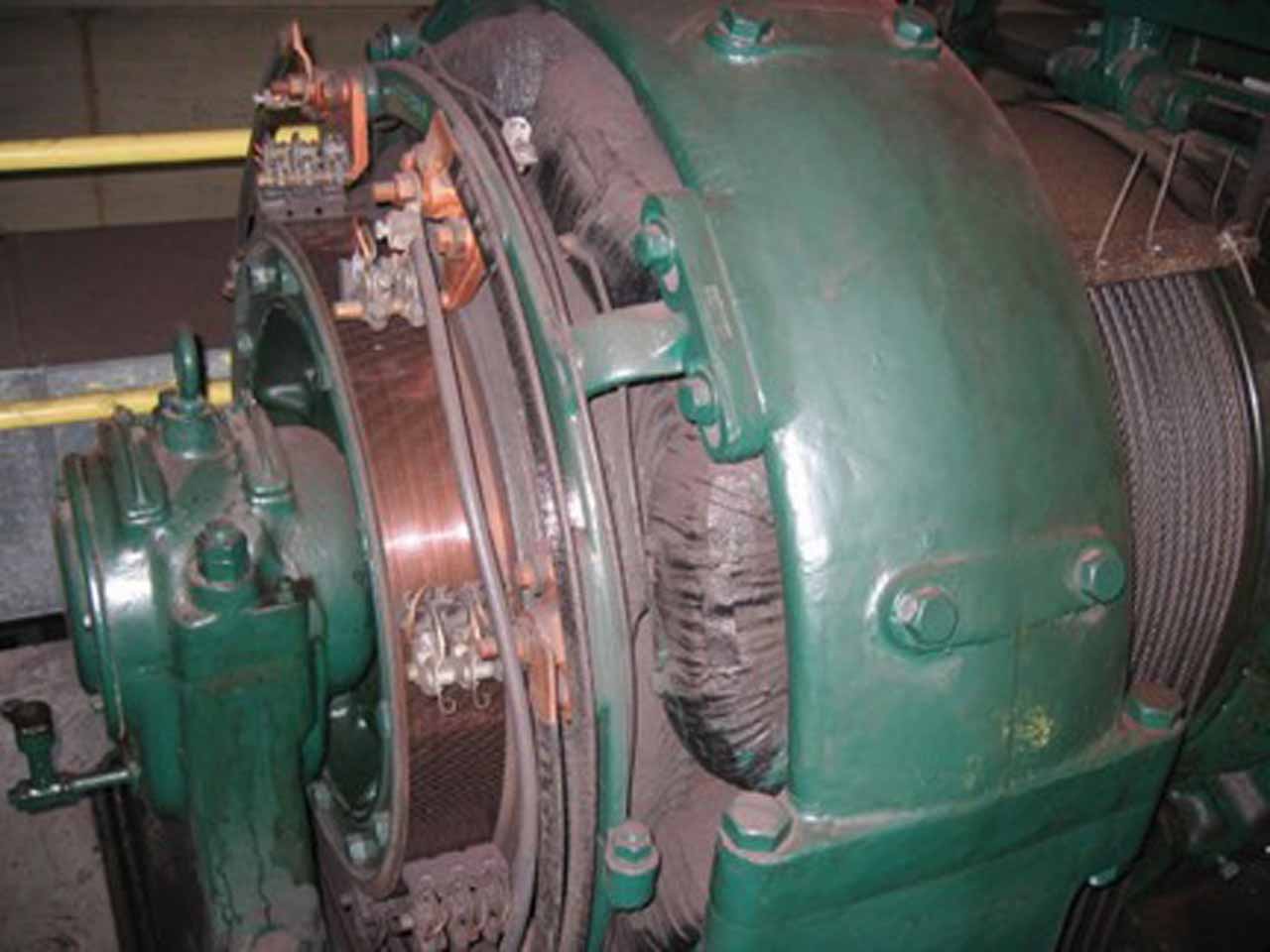
Traditional equipment utilized DC machines that used commutators and brushes and had bearings that needed constant attention. The machines in common use today are AC and require little maintenance, except housekeeping and examination. They are typically provided with sealed bearings. It is not hard to argue the point that no maintenance required means that it works or it doesn’t. If it doesn’t, then it is a replacement. With little maintenance to do, except cleaning the machine itself, there are other maintenance items around the driving machine.
With modern elevator systems using a solid-state motor controller, detecting the rotation of the machine is required in order to provide a secondary encoding device. These encoders are typically mounted on the end of a motor or machine shaft and need replacement, but not maintenance. Most of these devices are optical, encased and very sturdy. When they do not work properly, the system shuts down, entering a safe mode of operation. Replacing them is done from the car top with the power off and the blocking means engaged, restraining the system in place.
With the requirements for reliable electronic circuitry in critical operating circuits, a critical failure of an electronic part will rarely cause any catastrophic movements. It is designed to be safe. The electrical design must employ reliability and checking methods to verify the function of critical operating circuits. The mechanical design must employ factors of safety for critical elements using specified materials verified by certified organizations. If the design complies with the code, the component will either not fail or fail in a safe state and be replaced.
The traction grooves or surfaces of the driving-machine sheave must be inspected to ensure there is no buildup of debris or rouge. Generally, in all MRL systems today, inspection can be done from the car top, with the car at the top of its travel. In some designs, a ladder may need to be employed. If the car must be moved to where failure of a component could cause the car to become unmovable, there is a chance that the technician could get trapped on the car top in the overhead in a confined space. If any maintenance procedure requires this risk to be present, the code requires a means of egress from that space. This is usually accomplished through a ladder permanently available on the car top to egress from the top of the car, down through the emergency hatch onto the platform and out through the car door and hoistway entrance.
For example, if during the time the car top is at the top limit with the technician on the top of the car, they see a problem and are in the process of maintaining or repairing it, a fuse blows, a bolt breaks or any number of things can happen causing the car to become inoperative. Now the technician can’t get off the car through the top hoistway door. But the technician can get out if they could safely get into the car and go out the car door. This means of egress is required by Code.
With no brushes or lubrication required on the driving machines, they become as interesting as the rail brackets and rails. Check the brake pads, braking surfaces and sheave grooves.
Inspection and Test
For all MRL systems in the marketplace, inspector’s guides have been provided to NAESA International for reference by inspectors. The tests remain the same for either legacy systems or the newer MRL systems, but the location of testing is very different. Where the technician stands and what steps are required are detailed in these guides.
The tests required on the driving machine are to verify traction, verify the driving machine brake and emergency brake operation and the speed. Whereas these tests were done in a machine room (generally with the driving machine right there to see), now the machine is out of sight and a display is telling us the speed. This is no different from a percentage of legacy machines that are in remote locations. Since technicians have been able to test these for almost a century, it is also possible to test these newer systems from a location where there is a display device indicating direction and speed. Remember, this is at the test and inspection panel.
Whether sheave turning is directly visible or display devices show the speed of the sheave turning, the information is available. Since it is available, it can be inspected, tested and witnessed as though it were visible to the eye. The same technologies that allow accuracy to the millimeter on automatic operation are used to display the motion of the machine during an inspection. Since the elevators are operating hundreds of times a day without failure, it is not logical to doubt the display system during testing.
Adjustment, Repair and Replacement
The current driving machines have high reliability, low maintenance requirements and can operate hundreds of thousands of times. However, some do go bad and require replacement. The code requires that the replacement must be the same as the original. If the motor is listed, the replacement must be listed.
Because of the new locations of the driving machines, there is likely much less room to perform a replacement than from a machine room floor. This is a new hazard, and in some cases, special tools for the removal of the machine have been developed by the OEMs. The procedures and a description of any special tools should be provided in the Maintenance Control Program (MCP).
It is likely that the machine will not be altered, but occasionally an owner wants a faster unit, bigger capacity and more floors to be installed. These are typical alterations. The Code is clear about the requirements for alterations of driving machines. The Code specifies the types of changes that mandate further changes are required to be done to the system. At the time of this writing, and likely in the future, most MRL designs have a life cycle of 15 to 20 years.
Conclusion
The location for the MRL driving machine presents the challenges of access working in its new location and how the car top can be made into a safe working platform. With requirements for blocking means to safely land the elevator and prevent unintended movement, the car top is safe. Tasks were done from traditional car tops such as deflector sheave replacements, oiling, greasing bearings, replacing 2 to 1 sheaves on the top of the car and top of the counterweight, etc. These were done with no blocking means protections. Generally, the blocking means were tools brought to the job. There were fewer protections for these procedures than are now required for MRLs. This evolution in safety is good for the safety of elevator personnel in the future and should be viewed as a positive development. Having other equipment in addition to legacy equipment at the top of the hoistway does not greatly change the dynamics, given the presumed reliability of the driving machines expected. Only the frequencies change: Elevator personnel will perform maintenance more frequently from the top of the car.
Other requirements for this new working space include a lighting level equal to a machine room 19 fc (200 lux), fall protection (handrails) from the car top if the car top has more than 300 mm (12 in.) of space to the hoistway enclosure (though this predates the MRL Supplement), emergency stop switch requirements, working clearance requirements and egress requirements. The Code considered the requirements for a machine room and transferred all of these requirements, where possible, to the new working platform: the car top. Whereas technicians worked on the car top for many years in near darkness without car top handrails, now that environment is totally transformed into a safer location to perform the necessary work.
It is still a car top, with inherent dangers from movement, falling objects and many potential tripping hazards; however, due to the MRL code changes, the car top is a much improved working space from any legacy system in existence. The driving machine has become a large replacement component, no different really than that of a deflector sheave. When it stops working, replace it.
The procedures for maintenance, testing, inspection, adjustment, repair and replacement should be provided in the MCP to ensure that work performed by elevator personnel does not cause unsafe conditions.
Materials Required by the MCP
- For all driving machines, test and inspection procedures or methods
- Any product-specific driving machines; maintenance, repair, replacement, adjustment, test and inspection procedures or methods
- Schedule of maintenance requirements for driving machines
- Records of replacements
- Records of alterations
Brakes
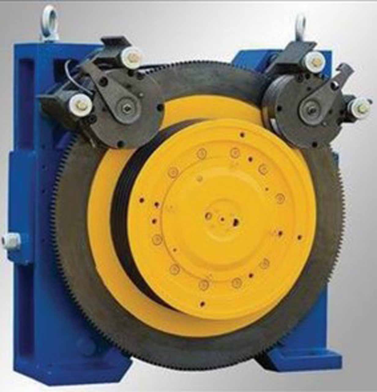
The prevention against uncontrolled movement of elevators is a cornerstone of elevator safety, and the primary devices that protect against it are the brakes. It is the primary means when the elevator is not moving, which arguably is most of the time an elevator is in operation. The designs of brakes have changed with the advent of MRLs and smaller driving machines.
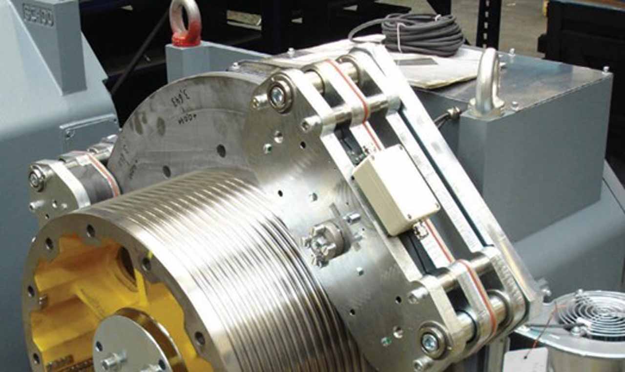
New suspension systems allow for smaller driving traction sheaves, which have to rotate proportionately faster to drive the elevator at reasonable speeds. With the smaller sheaves, the brakes are also smaller and more compact. The stopping force of the brake is a relationship between the surface area of the brake pads in contact with the moving surface, the coefficient of friction and the force that the pads exert on the moving component. Smaller machines have smaller surface areas to brake against. In legacy driving machines, these areas were much larger than those found in MRL units. The braking force per square area is much higher on MRL systems and, therefore, can lead to excessive wear in less time than in legacy equipment.
In legacy equipment, the thickness of the pads is usually visible when inspecting the brake shoes; with MRLs some pads are not visible. With new locations of the driving machines, the accessibility of the brakes is severely reduced relative to legacy driving machines, therefore requiring a different approach to determine that the brake pads have not worn down too much. Typically, feeler gauges are used to determine if the pads have acceptable thickness. Each manufacturer will have information on the testing and adjustment procedures. The Code also requires certain information to be on a plate mounted on each brake, such as the range of total masses (car with attachments and its load) for which it is permitted to be used, the range of speeds at which it is set to operate and criteria such as rail lubrication requirements that are critical to its performance. The Code also requires the brake information plate be readily visible.
The failure of brakes due to the wearing of the brake material ultimately led to the addition of another brake; however, many methods have been devised to prevent the brake wear from becoming a problem. Motion limit switches will prevent the elevator from restarting if the material thickness is severely reduced. This is not required by the Code, however, and, therefore, some systems rely solely on maintenance and the visual examination of the thickness of the pads to ensure proper operation and function.
Over time, the safeguard to prevent failure of the driving-machine brake was to provide a redundant brake (emergency brake), which has been code required since 2000. The emergency brake has other code-required conditions to ensure minimal brake-pad wear. For example, it is not allowed to drop onto a moving braking surface, except in an emergency, unlike the driving-machine brake, which is designed to be used on a moving braking surface (such as at reduced braking force during releveling). Therefore, the brake pad of the emergency brake is designed to always have full brake force at all times in the event of a failure of the driving-machine brake.
Maintenance
MRL driving machines are usually very compact, and most use a disc brake fully housed in the brake assembly. There is little maintenance to be performed on them. There are generally no lubrication requirements and no means by which to clean them. In some designs, it may be possible to see portions of the disc; however, since they are a disposable unit, there is little to do but test their operation and replace them if they do not perform.
The Code elaborates what components of the brake require maintenance including the residual pads (antimagnetic pad), linings and running clearances, pins and levers, springs, sleeves and guide bushings, discs and drums and brake coils and plungers.
Most of these requirements assume a traditional brake in which these components are available to be disassembled and maintained. Each manufacturer must provide any special brake maintenance instructions in the MCP.
Inspection and Testing
In all elevators, the brakes must be designed and tested to hold a load and bring a full speed elevator to a stop with full load. Depending on the class of elevator, the load is 125% of rated load for passengers, and up to 150% of rated load for C2, or for very large freights and special loading conditions, such as where a fork lift may be driven onto the elevator to drop off a load, and only then the load is moved.
Since the brakes of MRL units are located in the hoistway, testing and inspection cannot generally be performed while directly observing them in operation. This is not a new hazard; the testing of the brake is usually done from the controller after putting weights into the car at the bottom floor and demonstrating its ability to hold the required loads. The difference with MRL systems is that, since visual confirmation is not possible in all cases, this test must be performed at an inspection and test panel, where an indication of direction, speed and proximity to the landing is displayed.
Two sets of tests must be performed: one for the driving-machine brake and the same for the emergency brake.
Adjustment, Repair and Replacement
In the life cycle of the elevator, adjusting and readjusting will be performed many times; depending on the technology used for the mechanical brake. All brakes wear. They are designed with a friction material that over time and use will require replacing. Some designs require that adjustments be made to ensure correct operation. There is more likelihood that the only procedure to be performed on an MRL brake is a replacement. However, there are few things that will be adjusted or repaired.
The Code directly requires that any work done that can affect the holding capacity or decelerating capacity shall be adjusted and checked by a means to verify proper function and holding capacity. The Code now requires all brake adjustment means have a seal after testing the brake to assure the adjustments are maintained.
The same requirement should apply to the emergency brake. The general requirement for replacements is that they must be at least the same strength as the driving-machine brake. It is critical to ensure that any work performed to either brake be verified by testing.
Conclusion
Without a properly operating brake, the car can move with the doors open and run in unchecked acceleration into a terminal. These are unacceptable conditions.
The advent of MRL units does not increase this risk. However, since checking the brake pads and brake operation were more easily done from a machine room, there had to be improvements in brake technology to not be as reliant on maintenance and ensure that with the new locations, checking the brake pads is accomplished as easily and dependably as from a machine room. The proper procedures for testing, inspection, adjustment, repair and replacement must be provided in the MCP.
Materials Required by the MCP
- Any product-specific procedures or methods for tests and inspections
- Schedule of maintenance requirements
- Records of replacements
- Records of alterations
Learning-Reinforcement Questions
Use the below learning-reinforcement questions to study for the Continuing Education Assessment Exam available online at Elevator Books or on p. 127 of this issue.
- What are the function and importance of the electric driving machines and brakes?
- What changes and requirements have MRL units brought to these tasks?
- What are the maintenance, inspection and testing, and repair and replacement specifics for electric driving machines?
- What are the maintenance, inspection and testing, and repair and replacement specifics for the brakes?
- What is the cornerstone of elevator safety?

Get more of Elevator World. Sign up for our free e-newsletter.
![]()


![]()