Maintenance on New Equipment Designs: Governor and Safety Systems and Suspension Means
Sep 1, 2024
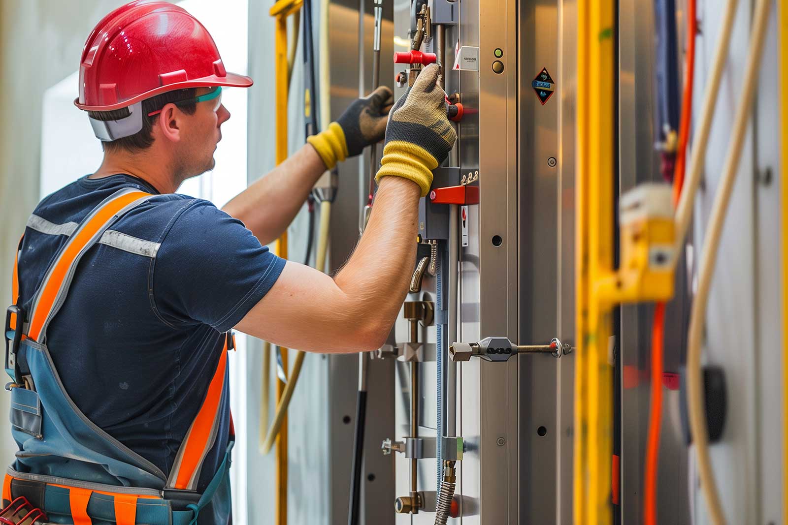
An inside look
Value: 1 contact hour (0.1 CEU)
This article is approved for Continuing Education by NAEC for CET®, CAT® and QEI credit and by NAESA International for QEI.
EW Continuing Education is currently approved in the following states: AL, AR, CO, FL, GA, IL, IN, KY, MD, MO, MS, MT, NJ, OK, PA, UT, VA, VT, WA, WI and WV | Canadian Province of BC & ON. Please check for specific course verification of approval at Elevator Books.
Learning Objectives
After reading this article, you should have learned about:
- The function and importance of the governor and safety
- How to perform maintenance, inspection and testing, and repair and replacement on the governor and safety
- The differences in the governer and safety systems for MRLs
- How to perform maintenance, inspection and testing, and repair and replacement on various types of elevator suspension means
- Steel-wire ropes versus coated steel belts
Governor and Safety Systems
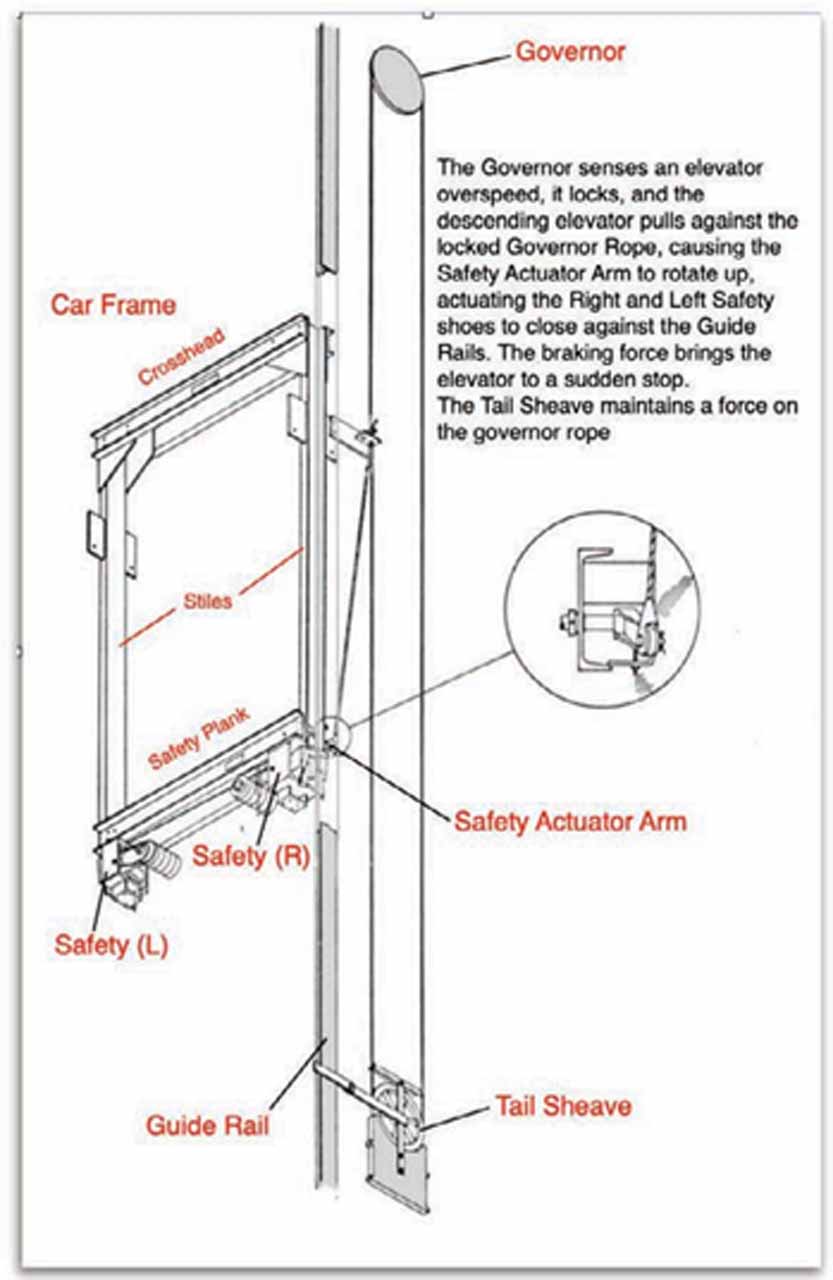
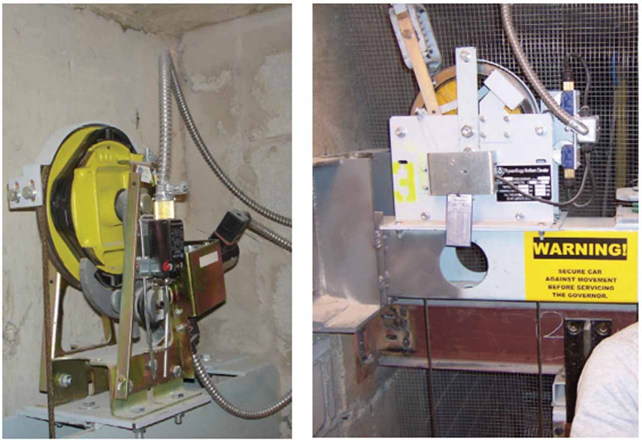
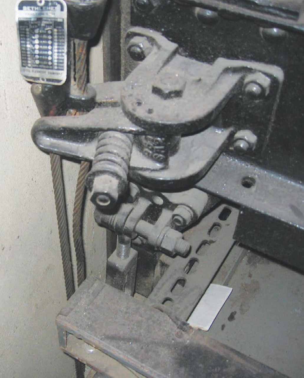
In all electric elevators and roped hydraulic elevators, the fundamental system for protecting against overspeed and free fall of the elevator is the governor and safety (Figure 1). The governor acts as a speed detector; at predetermined speeds two protections will trip: The first is an overspeed switch designed to electrically stop the elevator, and the other is a mechanical activator that will capture the governor rope and mechanically bring the elevator to a stop. While the elevator is moving and the governor rope is captured, the governor rope is being pulled on by a force known as the governor pull-through force. This pull-through force is then used by the car safety to mechanically actuate and frictionally engage on the guide rails.
The stopping force exerted by the safety is tremendous and requires that several key components remain free from debris, corrosion, physical damage, unintended or incorrect lubrication or other disabling condition. Due to the importance of this function, the governor and safety system are functionally tested at intervals established by the AHJ, typically annually with no load and every five years with full load.
With legacy elevator systems, most governors are accessible from the floor (or sub-floor) of the machine room and the safety located on the car. The testing is performed from the machine room and the elevator personnel are only on the car top after the test to examine the releasing carrier, if present, and results of the safety test. This is a physical measurement of the slide, visible on the rail face as scratches in the milled surface where the safety engaged the rail to bring the car to a stop.
It is important to note that older safety systems and most systems having a speed of 1.7 m/s (350 fpm) or greater use a releasing carrier to hold the governor rope steady at the car to prevent the acceleration of the car from inadvertently actuating the safety. Over time, this critical device can become seized and not allow the safety to actuate at all. It is critical to verify that the releasing carrier is free to release the governor rope when called upon to function.
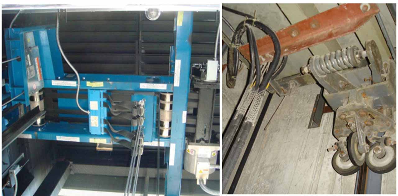
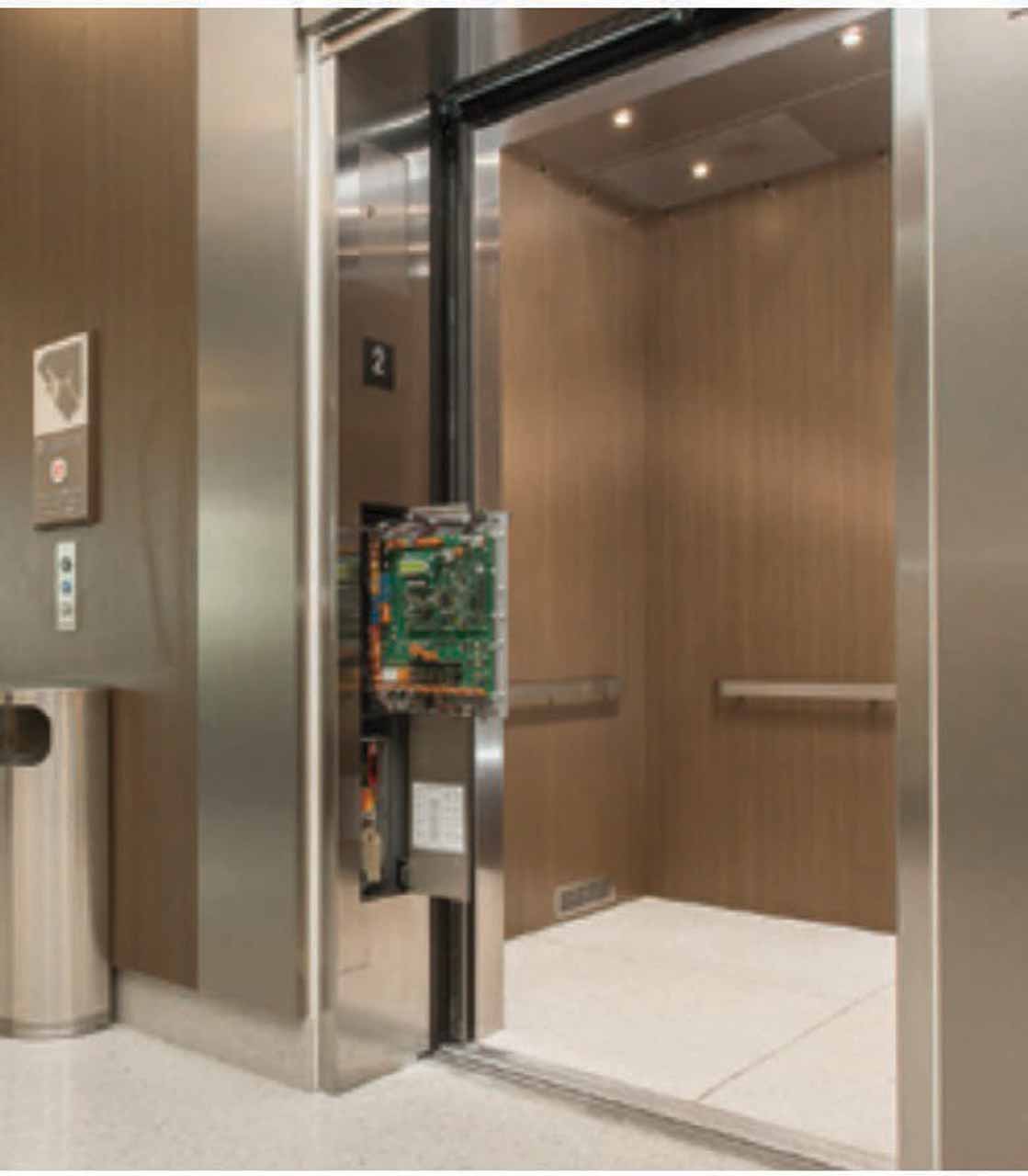
Machine-room-less (MRL) elevators, which operate at relatively slower speeds (less than 2.5 m/s [500 fpm]), usually do not have a releasing carrier (Figure 3). The governors are located in the hoistway and, of course, the safeties are still located on the car. The new governor locations present new risks because the working space, where the elevator personnel will be performing tasks, is on the car top. It is not possible to manually trip the governor from the car top because the technician would be on the car top moving down, putting the governor out of reach as it traveled. Therefore, the Code requires that there is an access door or other means to trip the governor. This procedure must be as sure as the method used in traditional systems.
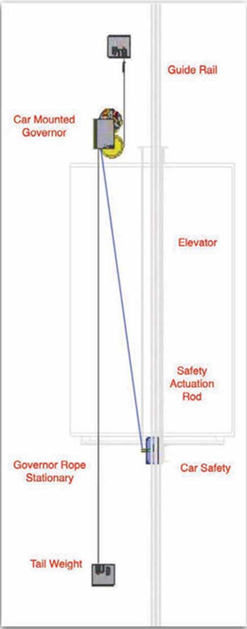
New governor/safety system designs include car-mounted governors. In these systems, the governor rope is stationary with a tail weight and a friction governor sheave accessible on the top of the car, connected to the car safety actuator. Like any governor mounted in the hoistway, it is exposed to hoistway dirt and debris, and careful attention must be made to assure this doesn’t affect normal operation of the governor. For example, if the governor will trip in error, this will cause unexpected sudden stops. Maintenance procedures assure cleaning is performed relative to the environment being exposed to this new condition of dirt and debris.
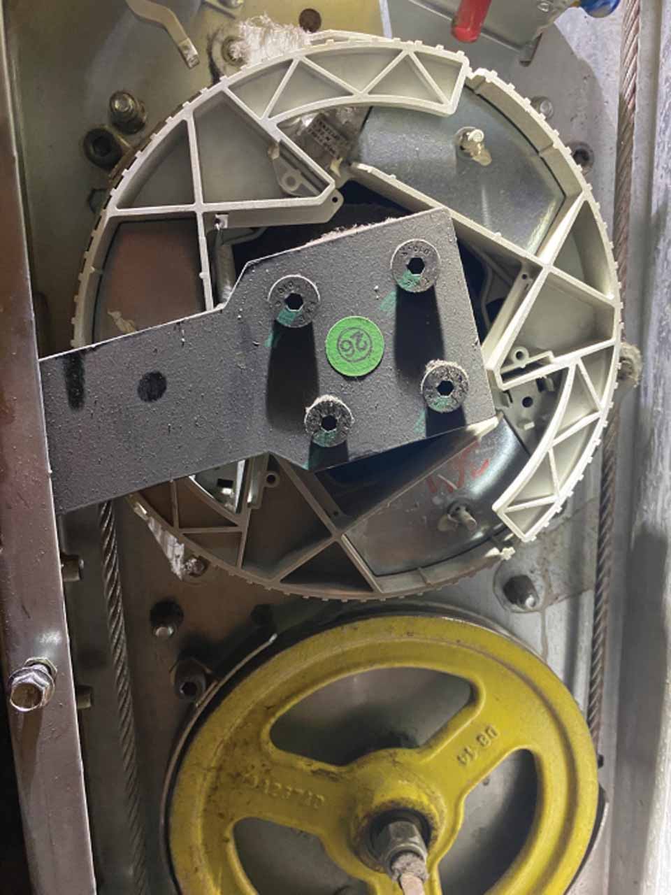
In the car-mounted governor (Figure 6) arrangement shown in Figure 5, unlike traditional locations, the governor is located on the top of the car with the governor rope mounted stationary from the top to the bottom of the hoistway with a tail weight to maintain governor rope tension with the governor moving with the car. It is novel and eliminates the requirements for external hoistway enclosure access. They incorporate an overspeed switch and a means to reset the governor from outside the hoistway located via the Test and Inspection Panel. Maintenance on this type of governor must be included in the Maintenance Control Program (MCP) recognizing the effects on dirt and debris that will accumulate on its components and potentially cause it to nuisance trip.
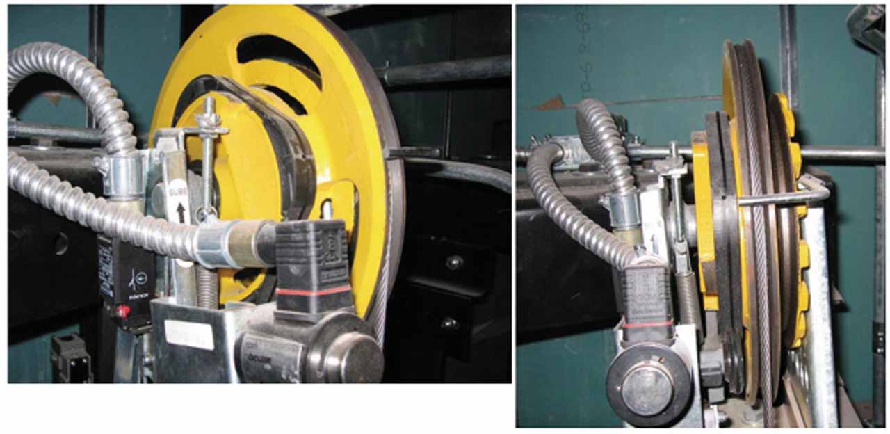
Furthermore, the governor and governor overspeed switches are required to be manually reset. This was an easy task from the floor of the machine room. This can be done with an MRL in only two ways: providing an access door to get to the governor, or to provide another means that can be used to electrically reset the governors. This also illustrates one advantage of using friction-type governors (Figure 4): they are self-resetting mechanically; there is no dog to “undog” as in older and larger governors. The overspeed mechanism grabs a moving component of the traction pulley, and it retracts once the governor is moved. This is done by moving the car, allowing the overspeed mechanism to return to the neutral position.
As elevator personnel already work on the car top, one might ask, “What is the new risk?” It is a good question. “Estimating” risk considers the elements of a hazardous scenario, which include the duration and frequency of a task, the location where the work is performed, the potential severity of a failure and the people involved in the task. In this case, the increase in the duration on the car top, the possibility of the car moving unexpectedly and the frequency of doing more complex tasks on the car top increase the risk of injury to the elevator personnel. Procedures previously accomplished from a solid floor are now to be performed where there is a real possibility of dropping tools, falling off the car top, tripping over crossheads, fans and wiring and being in a position where unexpected car movement can injure, particularly when the actions of the technician can be the cause of the car movement. These risks did not exist for as long a duration or have as severe an effect when the work was performed in a machine room.
The possibility of the car moving unexpectedly as a result of actions taken by elevator personnel resulted in the Code being written to provide several protections requirements.
Maintenance
Maintenance procedures should be provided to the technician in order to know what normal and abnormal parameters are, and how to perform maintenance, inspection and testing, and repair and replacement. Experience will be an important component, but even longtime experience may not be a match for the new locations. There should be a safe way to perform the work. Elevator personnel should ask for and follow the company’s training and procedures. Many companies now require a Job Hazard Assessment to establish the hazards for specific procedures including maintenance, testing, repairing, etc. In some cases, the required personal protective equipment is identified. Technicians should review any Job Hazard Assessment prior to performing work.
The actual maintenance of a governor in the hoistway is not far different from a governor in a machine room, except that while the elevator is running full speed without an access door, it is difficult to see the governor turning and that accumulation of dirt is more likely. Dirt and dust combined with moisture and oil from the rope can combine to build up a caked surface along the groove of the governor. This is a potentially dangerous thing, especially if the governor uses traction of the groove as the pull-through force to set the safety, which is the most common type of governor used in MRLs. Maintenance must consist of a visual examination of the governor to clean off any potential accumulations of this debris. In many cases, the debris also accumulates on the rope if debris is collecting on the governor groove. The accumulation of debris on the rope is also an issue with dogged governors; the groove on the governor pulley does not contribute to the pull through; only the governor dog against the governor frame provides it. If the rope is caked with debris, it may not function properly.
Examination and toggling of the governor switches are good practice to ensure they are not frozen or unable to function as intended. Verify that they trip as intended and require a manual reset as required by the Code. One or two switches may be available, and in some MRL designs, there may be a motor-driven or electro-magnetic resetting device so the button can manually reset the governor and switches from outside the hoistway. If this feature is included in the design, it will require a person to do the manual reset from a remote location in order to verify its operation.
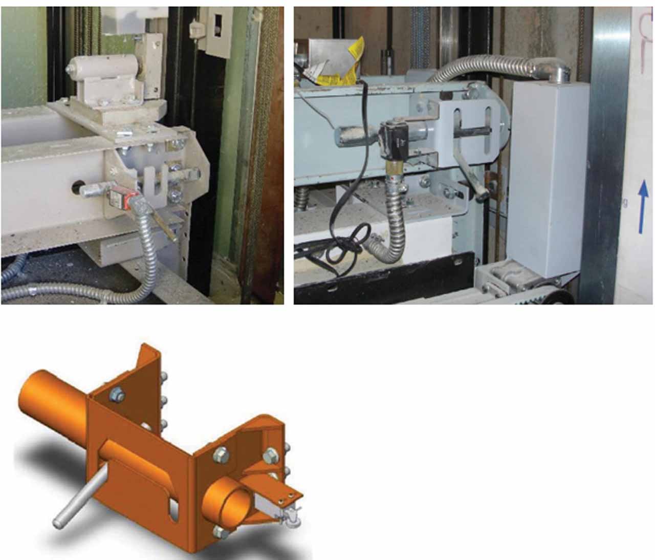
If there is a need for significant cleaning of the governor or if the technician cannot visually inspect the entire groove of the governor, it will be necessary to block the car and remove the governor rope. The Code requires a blocking means (Figure 7) to assure the car cannot move while performing this procedure if work is to be done from the car top and if that work can cause unexpected vertical movement of the car. The Code requires that the instructions for using the blocking means be visible in the working area. Envisioning personnel who have no training on the inspection and testing of this unique arrangement exist, instructions for the use of the blocking device and the testing and inspection procedure must be provided on a placard.
Some systems do not have tasks that can cause unexpected movement and, therefore, do not have a blocking means. However, they do have a restraint method to protect against the car moving down without the governor fully operational when the governor is being serviced.
If present, the blocking means or the restraint system must be used whenever the governor is disabled. In order to clean the governor rope or to clean the governor, the governor rope must be removed; therefore, there is no effective operational safety system. It would be rare for the car to fail at that particular moment; however, it only takes a couple of minutes to use the blocking means or restraint system.
Maintenance on the safety typically includes a visual inspection of the safety jaws located in the pit area. Physically moving the wedges to verify freedom of movement and a toggling of the safety-operated (plank) switch are minimal items to check. Any debris in the safety mechanism can cause it to bind and even fail. Because of the location under the car, it may be difficult to accomplish without two people.
If a releasing carrier is a component of the safety system, a verification of the correct pull-out force must be done to ensure that it has not become seized due to debris or oxidation of the components.
These maintenance procedures are a vital part of the training technicians receive. The critical nature of the correct operation of the governor and safety are essential for safety and to maintain Code compliance. The governors with devices to reset the governor switches must have instructions in the MCP. That is unique to an MRL design.
Inspection and Testing
Inspection and test procedures must be in the MCP and available during an inspection if the equipment is an MRL or if the equipment is unique: that is, different from traditional equipment. For instance, if the governor is in the hoistway, there must be an equally safe way to test the governor. Traditional governors are usually located on a floor in a machine room; today, they can be mounted in the hoistway on the rail, in the overhead structure, in the pit on the top of the car or to the hoistway wall.
For acceptance testing, the car is generally prepared for a demonstration of the governor overspeed and safety setting by being taken out of service. From the top of the car or from an access door, the technician and inspector spin the governor with the governor rope off to see the trip speed and that it trips to ensure it is working correctly. After verification of the operation and data plate information, they leave the car top and operate the car from the controller; the car is oversped onto the car safety with a full load.
If there is a counterweight safety, the previous steps are done, and then the car is oversped in the up direction onto the counterweight safety. The counterweight governor is allowed to trip at a slightly higher speed than the car so both safeties won’t be set simultaneously. If there are two governors and safeties, use a tie wire to prevent one governor from tripping while testing the other. This wire must be removed after the inspection is complete.
For Category 1 tests, the car is run empty at inspection speed, and the governor is manually tripped. For Category 5 tests, a full load is required, but the test is done at rated speed (not overspeed) and is manually tripped. When the governor is in the hoistway, a procedure must be provided to explain how to do this. In some cases, there is a governor trip button outside the hoistway or an access door provided to trip the mechanism. When the governor is not in a machine room, this procedure must be provided in the MCP.
Testing a governor when on a machine-room floor does not have the risk of the floor moving away from the personnel doing the testing, but if the procedure is from the car top, there may be unexpected movement of the car. This creates risk of being on the car, a failure occurring and the car overspeeding without a governor attached in the safety system to provide enough pull-through and, therefore, no way to set the safety. To ensure safety, follow the procedures as detailed in the MCP or the testing procedures provided by the manufacturer.
Testing the governor and safety system on new equipment must be done from the landing and the ability to directly observe the correct operation of the governor. The difficult task is taching the car speed by measuring the governor rope speed with a tachometer to assure it attains the correct speed for the test. Because it would be unsafe to do this task with the governor in the hoistway, the Code requires that an access door be provided or that a reliable display system provide the same information at the same location as the test is performed. The purpose of the means necessary for tests is to provide the equivalent information that is no longer available directly from the floor of a machine room.
The safety test results are verified by measuring the slide distances, which are evidenced by the scratches left on the rail face. The lengths (subtracting the length of the wedge) are measured and compared to a table in the code.
With the use of advanced measuring tools, the acceleration of the car can be recorded and displayed, providing identical data but with more detail of actual stopping. The difference between the two methods is that one measures the length of the slide on the rails, giving a calculated average stopping force, and the other displays the instantaneous stopping force every millisecond from full speed to zero, on a graph with mathematical precision. These systems will become more prevalent.
Adjustment, Repair and Replacement
Should a governor, or any component of the safety system, need altering, repair or replacement, blocking or restraining the car is required for any governor system located where it is accessed from the car top. While the governor is disabled, it cannot perform the function, and if the technician is standing on the car, they are in an unsafe condition. Use the blocking means provided. Also, the governor is a certified device and must be replaced only with a similarly certified device.
Conclusion
The governor and safety are not new equipment; the governor is simply in a different location. Maintainers must understand the risks of the new location and use the provided safety devices when working on these systems. Testing procedures necessarily changed because of the new locations. Having the correct procedures on-site will help to correctly test the new devices and not overlook a test because there wasn’t a way to do it the old way. Each owner must have these procedures in the MCP and be available to elevator personnel.
NAESA International has requested testing documents from OEMs in order to have them available to inspectors in an online format. These documents should also be on the job for reference by any elevator personnel who visit the job. OEMs typically provide these documents to the inspection community to ensure that the tests are run safely and correctly.
The MCP materials vary in detail by company; however, they must include information relevant to the maintenance, test and inspection, adjustment, repair and replacement of the governor and safety system if the system is unique or product specific. If not, only the test and inspection procedures are required. Whether a governor is in a room or in a machinery space, the actual procedures are typically the same; it is just the location that differs. This requires knowledge of the use of the means to prevent unexpected car movement; this is the important point to take away from this section.
Materials Required by the MCP
- For all governors, test and inspection procedures or methods
- Any product-specific governors, the maintenance, repair, replacement, adjustment, test and inspection procedures or methods
- Schedule of maintenance requirements for governor and safety
- Records of tests
- Records of replacements
- Records of alterations
Suspension Means
Since 1998, several novel technologies for elevator suspension means have found their way into the marketplace. Present technologies are now codified in ASME A17.6, Standard for Elevator Suspension, Compensation and Governor Systems. These include many steel-wire-rope technologies, aramid technologies and coated-steel-belt technologies. With each new suspension system that varies from the traditional steel-wire ropes, new maintenance, test and inspection and replacement procedures must be provided.
For more than a century, the only allowable suspension means for elevators was steel-wire rope, with a minimum number of ropes depending on the type of elevator, and a minimum rope diameter and wire-size diameter. During that time, many alternate-steel-wire ropes were introduced, which weren’t addressed by A17.1, causing a need to provide a standard for various steel-wire-rope constructions.
Aramid and coated belts were also being introduced, and it was agreed by the A17 Standards Committee that all suspension technologies of the day would be included in the new A17.6 code. In addition, all replacement criteria will be located in this document and removed from A17.1.
Since the first edition, aramid is no longer permitted as a suspension means, and unique suspension for a wind turbine tower elevator, use of aircraft cable and coated steel ropes have been added to ASME A17.6.
It should also be noted that the existence of most present-day MRL units is the result of smaller driving machines with new suspension systems. As a result of these innovations, many new systems will enter the marketplace, and each suspension system will have its own unique requirements for maintenance, inspection and testing.
Maintenance
With steel-wire rope, maintenance consists of keeping it clean and lightly lubricated. A properly designed traction system in the most favorable conditions should last for decades. The use of oversized sheaves, slower speeds and U-grooves has given way as demands for faster speeds, tighter traction tolerances and smaller machines have become the norm. Even with the same level of cleanliness and light lubrication, rope life has seemed to shorten, a tradeoff to the more exacting engineering available today for most legacy designs. While the appearance of shorter rope life seems like a negative, it is often traded for less-expensive total system costs.
Steel-wire ropes with undersized diameters have entered the marketplace in which these factors are evident and important. The appearance of a lack of robustness is traded off for even smaller systems with other values built into the overall system. But even with these tradeoffs, the systems are safe, just different from legacy systems.
No matter what the steel-wire rope design is, maintenance is keeping the steel wire-ropes clean and lightly lubricated. An excerpt from the Wirerope Works Technical Bulletin Number 2 from Bethlehem Elevator Rope Co.:
“Field Lubrication
Field lubrication is necessary to:
- minimize wear between ropes and sheaves,
- reduce friction between the wires,
- minimize corrosion due to atmospheric and/or operating conditions,
- help reduce bending fatigue by allowing movement between the wires and strands.
The proper field lubricant must be used so the traction relationship between the hoist ropes and the drive drums is not adversely affected. The lubricant should also be compatible with the strand and core lubricants, and have good rope penetrating properties.”
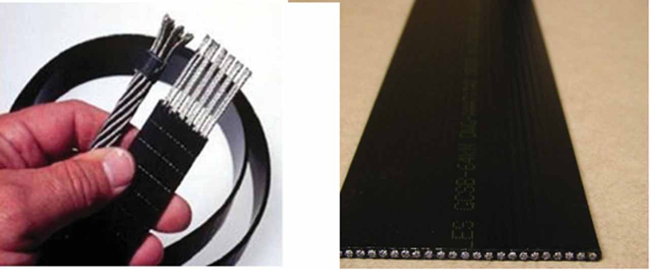
The popular suspension technology today is coated steel belts (CSBs). With CSBs, keeping them clean is the main concern. No lubrication is required, and no maintenance is required except examination for replacement criteria. Failures of CSBs include the cords breaking through the elastomeric coatings, some reports of early failure and not lasting as long as expected. Monitoring the life of these suspension systems has some controversy. The Code defines residual strength as “the actual breaking strength of a suspension member at any time during its operational life cycle.” Companies have tried to use cycle counting and statistical analysis as equivalent in determining the “actual strength.” This has yet to be thoroughly cleaned up in Code, and devices that determine cord breakage remain required by all jurisdictions at the time of this writing.
Inspection and Test
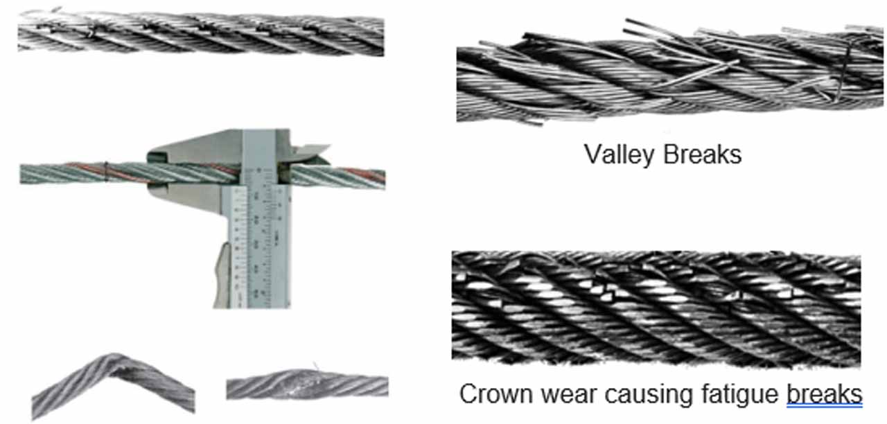
Maintaining Code compliance on steel-wire ropes includes inspecting for wire breaks, both crown and valley breaks, measuring for diameter reduction and noticing if rouge is present and making the number of wire break and diameter reductions appropriate as a result of this unfavorable condition. The procedure for inspection is well addressed in the Bethlehem Elevator Rope, Service Bulletins 1 and 2. These are a great resource for the techniques and important technical aspects of inspecting steel-wire rope, and all technicians should have a copy of the complete set. They are available at several locations; Williamsport Wire Rope has them available on their website, and they are also available from NAESA International.
Inspect CSBs for a steel cord extruding through the coating, and notice if rouge is present for code compliance. Because the cords are encased in a coating, tools have been developed to electrically determine if any wires are broken. That monitoring device is usually located in the driving-machine structure where the belts terminate. The device must have a level of reliability to ensure that it is working at all times. If it detects a problem, it will remove the elevator from operation.
Excerpts from Otis’ Gen2® Elevator Inspection Guide:
“Visual Inspection
Even though coated-steel belts are designed to last two to three times longer than traditional elevator wire ropes, an annual visual inspection is recommended. This procedure defines the technique for the visual inspection of coated-steel belts. There are two main criteria for coated-steel belt replacements, evidence of wire strand breakage or evidence of polyurethane degradation.
- Using top of car inspection, run elevator from top of hoistway to bottom of hoistway.
- Stop as needed to inspect the coated-steel belts using the following images for comparison and recommended action. (Note: These images are of belts tested at our test facility and not from actual installations.)
- Inspect coated-steel belts terminations, springs, nuts, cotter pins, nylon washers and rod condition.
- Egress car top.
- Replace all coated-steel belts if any one in the set requires replacement.
“Otis’ Coated-Steel Belt (CSB) Inspection Procedure using the Pulse™ System
The Pulse system is the Otis commercial solution for constantly ensuring belt integrity. The Pulse system monitors the condition of the steel cords inside the CSB continuously by measuring electrical resistance and signals the car controller of the CSB status. The CSB status is communicated as an alert or an alarm. Alerts are often provided more than a year in advance of when belts need replacement. Alarms occur when immediate service is required and ensure the elevator is brought to the nearest landing so passengers can exit. If the elevator has the REM® system installed, alerts, alarms and system health is automatically reported to local personnel.
The belts need to be replaced when:
- There are severe cord imprints visible on the surface of the belt
- There are exposed cords outside the belt
- There are exposed wires outside the belt
- The belt is cut
The belts need to be monitored carefully each year when:
- There are polished spots on the traction side of the belt
- There is severe rouge on the belt”
With all suspension technologies, proper tensioning is required to maximize the life of the suspension members and traction sheaves. Improper tensioning can lead to loss of suspension, parting of suspension members, and destruction of components. Proper tensioning is required by Section 8.6 to be regularly checked.
Adjustment, Repair and Replacement
No repairs or alterations are allowed for any suspension system. Adjustments can be made such as a member (individual component of a suspension means, such as one rope or one belt) shortening and with newer suspension systems, associated devices that may require adjustments. The only allowed replacements are the same for all suspension systems: verify tension and correct tension differences and the replacement of only one damaged member prior to the conveyance being turned over and placed into service. After that, all members in a set must be replaced.
Conclusion
The use of CSB and coated steel rope types of suspension systems has reduced maintenance and increased the use of automatic monitoring systems. Monitoring systems, in concert with visual inspections by the technician, provide for system integrity throughout the life cycle of the systems. With reliable, self-monitoring sub-systems continuously determining the state of the individual suspension members, the elevator is safely suspended.
Requirements for procedures for tests include periodic inspections, required maintenance, replacements, adjustments and repairs to be provided in the MCP for various components of the suspension systems. This is to ensure that when the technician sees these technologies for the first time, he or she will have the information necessary to perform these tasks.
Materials Required by the MCP
- Any product-specific procedures or methods for tests, inspections, maintenance, adjustment, replacement and repairs
- Any product-specific procedures or methods for traction loss-detection means, broken suspension member detection means and residual strength detection means
- Schedule of maintenance requirements
- Records of replacements
- Records of alterations
Learning-Reinforcement Questions
Use the below learning-reinforcement questions to study for the Continuing Education Assessment Exam available online at Elevator Books or on p. 145 of this issue.
- What are the function and importance of the governor and safety system?
- What are the maintenance, inspection and testing, and repair and replacement specifics for the governor and safety system?
- What are differences in the governor and safety systems for MRLs?
- What are the maintenance, inspection and testing, and repair and replacement specifics for elevator suspension means?
- What are the key differences between steel-wire ropes and CSBs?
Get more of Elevator World. Sign up for our free e-newsletter.
