Metal Raceways in Elevator Work
Aug 1, 2013

The National Electrical Code (NEC) devotes an entire article (NEC 620) to requirements for elevator wiring, along with other specialized mandates for dumbwaiters, escalators, moving lifts and stairway chairlifts (ELEVATOR WORLD, April and June 2012). The code’s overall purpose, stated in its introduction, is the practical safeguarding of persons and property from hazards arising from the use of electricity. Since significant amounts of electrical power, control and auxiliary wiring are required to lift people and material to ever-greater heights, designers and installers need dependable knowledge and expertise beyond what any individual could acquire through experience and intuition.
Learning Objectives
After reading this article, you should have learned about:
♦ The role of the NEC in electrical installations for elevators
♦ The relationship between the NEC and the ASME A17.1-2007/CSA B44-07: Safety Code for Elevators and Escalators
♦ The types of wiring permitted for elevator machine rooms,control rooms and hoistways
♦ How to transition between MC cable and EMT raceway
♦ Basic metal raceway bends
For years, the venerable elevator code ASME A17.1-2007/CSA B44-07: Safety Code for Elevators and Escalators has been the source for construction and maintenance information, including many diverse topics such as seismic requirements, machine-room lighting and car load capability. This elevator code lays the foundation for what must be achieved for a safe installation, and NEC follows with specific wiring requirements. The two codes are closely coordinated, and, together, are essential in elevator design and installation. This article will discuss specific applications in elevator work for metal raceways, especially electrical metallic tubing (EMT) and metal-clad cable (MC). It will also provide an overview of construction technologies, in which electricians and elevator technicians can not only comply with code mandates, but also create a professional and visually impressive end product.
NEC Article 620’s “Part I, General,” follows the general code template of opening with a statement of scope and definitions, plus overall requirements such as voltage limitations, working clearances and guarding. Since our focus, for now, is the use of metal raceways, the first area of interest is “Part III, Wiring.” It begins with a section titled “Wiring Methods,” which enumerates the requirements for elevators and related equipment, stating that in machinery spaces, control spaces, in or on cars, in machine rooms and control rooms (not including the traveling cables connecting the car and counterweight) and hoistway wiring, conductors and optical fibers are to be installed in:
- Rigid metal conduit (RMC)
- Intermediate metal conduit
- EMT
- Rigid nonmetallic conduit (PVC)
- Wireways
- MC, mineral-insulated (MI) or armored cable
This list is not all inclusive, because other wiring methods are permitted (with various limitations), notably where flexibility is needed at motors and similar equipment. Each principle wiring method is covered in its own article within the overall discussions of various wiring methods in NEC articles 320-398. Each article comprises two or more pages of design and installation specifications including such topics as spacing of supports, minimum bending radius and marking. Of particular interest in each are sections titled “Uses Permitted” and “Uses Not Permitted.” Whenever specification or installation of one of these wiring methods is contemplated, these sections should be carefully scrutinized to ensure a hazard is not built into the product or that costly rework does not become necessary. Each permitted method has unique characteristics that make it more or less appropriate for a particular application.
RMC is the most robust metal raceway in use and is permitted in all environments where any wiring is permitted, so it is included in the list of permitted wiring methods. It resembles galvanized water pipe (the tapered threads are identical and mutually compatible), but it has a smoother inside surface, and for that reason, water pipe is not accepted as electrical raceway. RMC is bent and threaded in the field and could be used for elevator work. However, it is expensive and time consuming to install, and for these reasons is not generally used, except where required due to the elevator being in a hazardous area.
The same comments apply to intermediate metal conduit. It is lighter and less expensive than RMC but still not commonly used in ordinary environments. EMT is well suited where metal raceway is called for and will be the primary focus of this discussion. Nonmetallic-sheathed cable (Type NM, trade name Romex) is prohibited in most non dwellings and not used in elevator work.
PVC is permitted in elevator work but is problematic for several reasons, and most professionals prefer EMT, even though PVC is less expensive. Prices are volatile, but as of June, 3/4-in. PVC was about 60% the price of EMT, with the differential increasing progressively in larger sizes. PVC is less rugged than EMT and has a large expansion coefficient with increase in temperature, so it is prone to sagging and buckling. Its best usages are underground, in concrete and in wet or corrosive areas such as dairy barns, but not in elevator work. If it is used, it must be agency-listed gray conduit – never water pipe.
MC is an excellent, robust and practical solution. A related version, Type AC, is similar in appearance, usage and installation procedure. The difference is that MC’s sheathing cannot be regarded as an equipment-grounding conductor, whereas Type AC’s sheathing can be so regarded, since it has a continuous conductive metal strip just inside and in contact with the sheathing. This, however, is a moot point, since MC contains an extra green equipment-grounding conductor. It is suitable where there is no requirement for redundant grounding, as in patient-care areas of healthcare facilities or in certain hazardous areas. (An elevator in a hospital would not ordinarily be considered a patient-care area.)
MC and EMT may be used interchangeably in elevator work, and it is a simple matter to transition from one to the other by terminating both segments in a 4-in. X 4-in. box or other enclosure and connecting the conductors inside with wire nuts. EMT has a more finished appearance and should be used where possible, whereas MC is appropriate where fished through studded walls and/or hollow spaces, where numerous close bends would be needed, or connecting to machinery that will be vibrating or may have to be moved for servicing.
Type MI cable is permitted for elevator work but not often seen because of its expense and complex installation procedure. It is a very reliable wiring method and well suited for hazardous areas. It consists of conductors surrounded by a highly refractory Type MI material inside copper tubing. It is terminated by means of an insulating cap, end seal, brass screw-on pot that cuts its own threads in the copper tubing, and a three-piece brass threaded gland and nut assembly.
Hoistway Wiring
In elevator hoistways, certain other wiring methods are permitted, but with restrictions. Cables used in Class 2 power-limited circuits are permitted to be installed between risers, signal equipment and operating devices, provided the cables are supported and protected from physical damage and are of a jacketed and flame-retardant type. In other words, this type of wiring does not require a metal raceway, although EMT and MC are permissible, and there are good reasons for using these. (However, Class 2 wiring may not be in the same raceway as power and light wiring.) If using cable with no raceway, the first step is to verify that the wiring does, indeed, qualify as Class 2. This is all examined in “NEC Article 725: Class 1, Class 2 and Class 3 Remote Control, Signaling and Power-Limited Circuits.” A Class 2 circuit may be defined as a remote-control, signaling or power-limited circuit powered by a Class 2 power source, such as a Class 2 transformer, thermocouple or circuit card. These possess sufficient internal impedance, so they cannot output enough power to ignite combustible material, and the voltage levels are not sufficient to constitute a shock hazard. With this type of wiring, certain code requirements for “ordinary” power and light wiring are relaxed. Certain other requirements apply, though, such as maintaining separation from wiring involving higher voltage or power levels, the idea being to ensure these do not infiltrate the Class 2 wiring.
Another wiring method that may find conditional use in elevator work is flexible cords and cables that are components of listed equipment and used in circuits operating at 30 V root mean square or less, or 42 VDC or less. These cords and cables must not exceed 6 ft. in length, must be supported and protected from physical damage and must be jacketed and flame retardant. Additionally, flexible metal conduit and liquid-tight flexible conduit (both metal and nonmetallic) wiring methods not to exceed 6 ft. are permitted in elevator hoistways. Flexible cords and cables or conductors grouped together, and taped and corded are permitted without the benefit of a raceway. They must be flame retardant and located to be protected from physical damage. Furthermore, they must be part of listed equipment, a driving machine or a driving brake. Additionally, a sump pump or oil-recovery pump in the pit may be cord connected. The cord must be a hard-usage, oil-resistant type, must not exceed 6 ft. and be protected from physical damage.
To summarize, wiring in a hoistway must be well designed and installed for two reasons: Any loose or out-of-place wiring material could catch on a passing car with very unfortunate results. Moreover, fire within a hoistway would be subject to tremendous updraft activity and could quickly involve upper levels. In cars, on the counterweight, and within machine rooms, control rooms and control spaces, similar additional wiring methods are permitted where flexibility is needed.
In most elevator installations, EMT and MC are the dominant wiring methods. As in all wiring, advance planning is key to achieving a quality end product, and this is particularly true where metal raceways are concerned. It is not very difficult to build an electrical raceway system that will work, at least for a while, but good electricians and elevator technicians aspire to a higher work standard. We want to create electrical structures that will be completely safe, reliable and characterized throughout by an outstanding professional appearance.
Machine-Room Wiring
In an elevator machine room, it is likely that the metal raceway will be mounted on the surface of finished walls and ceilings. As mentioned, EMT and MC are permitted here. A more professional and neater appearance is achieved by using EMT where possible. MC, while reliable and feasible in this setting, has a “busy” and less elegant appearance than EMT. It provides excellent grounding, since there is an enclosed green equipment grounding conductor, not relying upon the outer metal armor for this function. In the case of EMT, the pipe itself qualifies as a grounding means, but better electricians always “pull a green.” That way, if the raceway loses continuity, equipment grounding will be maintained.
A rotary MC cutter works well to sever MC armor. Slide off an 8-in. piece, cut the plastic strip out of the way and insert the prepared cable end into a connector. Use an insulating anti-short bushing (“red head”) to protect wire insulation. The connector will have a small opening so inspectors may verify the bushing is in place after installation. The insulating anti-short bushing is not necessary if using a snap-in connector.
Other than the rotary MC cutter, no specialized tools are needed – just a cordless drill with a Phillips screwdriver bit to mount boxes and secure the cable. In this connection, (preferably galvanized) drywall screws are commonly used. Installation requirements are found in NEC Article 330.
Using EMT is more complicated, especially in the process of bending its metal raceway to present a high-quality appearance, setting the tone for a quality job. Not technically conduit, EMT is tubing, properly described as metal raceway. However, in using EMT, electricians say they are putting wire in conduit, so on-the-job usage trumps precise terminology. An EMT bender is used for EMT, but to work with intermediate or rigid conduit in the same size, a bender one size larger is needed (to accommodate the greater outside diameter of these pipes). The tools needed to bend EMT range from simple, inexpensive hand benders to elaborate ratcheting and hydraulic models. Most elevator raceway work will involve modest branch circuit sizes, with the exception of the feeder coming from the supply panel, and power to the motor(s), so a set of hand benders, acquired as needed in different sizes, will suffice.
For small to medium-sized jobs, it is feasible to cut EMT with a hacksaw. On a larger scale, a handheld band saw is best. Another possibility is a chop saw equipped with an abrasive cutoff disc. In any event, metal cutting should be done outside the machine room, since metal dust and grindings are quite hazardous to circuit boards, where fine conductive particles can easily bridge adjacent traces with catastrophic results. A fine felt-tipped pen works well for marking lengths of EMT prior to cutting. All cut ends must be reamed to avoid insulation damage when conductors are pulled.
The object in bending conduit is to make a gradual, uniform bend, so there is no kink that would obstruct the wire-pulling operation. It gets more difficult when several bends face different directions, when it is necessary to install the tubing in tight quarters around obstacles. Beware of making a “dog’s leg,” which is a piece having the bends facing the wrong way relative to one another or not lying in the same plane (if required). Dog’s legs may be repaired by cutting between two bends and inserting a coupling so the bends correctly align.
Metal raceway should cling to wall or ceiling surfaces, as opposed to cutting through open spaces. Between box terminations, any conduit requires offset bends where it emerges from the first box. It is then clamped to the wall or ceiling, finally having another pair of offset bends where it enters the second box. An offset bender is used to make box bends (Figure 1).
Common EMT and Conduit Bends
To make a 90° stub-up bend in the case one or both ends of the bends are not predetermined, place the conduit in the bender, lay the pipe on a flat, level floor, make a vertical bend, then step on the footrest and press down while bending; otherwise, the bend will be incomplete, resulting in a poor radius. When starting at a predetermined location and ending with a right angle bend at a fixed location “brick wall,” it is necessary to make a stub-up deduction. The amount has to be deducted from the distance between the termination or coupling and brick wall.
The amount to be deducted depends upon the size of the pipe. Deductions are usually stamped on the benders. For 1/2-in. EMT, deduct 5 in.; for 3/4-in. EMT, deduct 6 in.; and for 1-in. EMT, deduct 8 in. To deduct, measure from the shoulder of the coupling or connector where the pipe will actually begin to the adjacent brick wall where the bend will lay. Subtract the deduction, then mark the pipe at that distance. Insert the pipe into the bender with the mark at the arrow. The bent piece will terminate at the desired location.
An offset bend, which consists of two bends at the same angle, is used to bring the pipe to a different plane, continuing in the same direction. The second bend points in the opposite direction, making parallel pipe runs on either side of the sloping segment. Center to center, the pipe length between the two bends is equal to the offset depth multiplied by the cosecant of the two identical bend angles. A cosecant is a trigonometric function found in trigonometric tables for any angle. It is best to use a pair of 30° bends to make an offset, because the cosecant is 2, which is easiest to remember and calculate. However, 30° is too big for offsets less than 4 in. In this case, common smaller angles are 22.5° (cosecant of 2.6) and 10° (cosecant of 5.76).
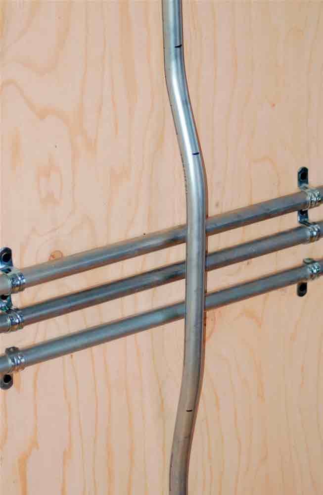
A saddle bend is used to run conduit over an obstacle, such as another raceway or water pipe. The three-point saddle is used for short distances, such as when a single pipe must be avoided. The first and last bends are equal, and the angle of the middle bend is equal to their sum. For example, if the beginning and ending bends are 22.5°, the center bend will be 45°. The four-point saddle bend resembles its three-point counterpart but is used when more than one obstacle is to be avoided (Figure 2). All angles are the same. It is actually made up of two offsets any distance apart – whatever is needed to avoid the obstruction.
Segmented (multi-shot) bends are necessary when parallel conduits must make a turn. That objective may be achieved by bending all pipes at the same angle, but where the best finish appearance is required, the segmented approach is better. If, for example, the innermost pipe needs a 90° bend, it could be created by making nine 10° bends. The number of bends and their angles is constant for each pipe, but they are set successively further apart so parallel spacing is maintained.
Conclusion
This has been a brief rundown on the principle of EMT and conduit bends. The subject is rather complex; entire books have been written on it. Commercial and industrial electricians spend a good part of their time bending metal raceway, so the procedures eventually become very familiar. In an elevator machine room, control room or hoistway, a very high standard of workmanship should be maintained, and it is hoped this brief overview will be helpful in that regard.
Learning-Reinforcement Questions
Use the below learning-reinforcement questions to study for the Continuing Education Assessment Exam available online at www.elevatorbooks.com or on p.
139 of this issue.
♦ What is a Class 2 circuit?
♦ When are flexible cords allowed in elevator installations?
♦ How do grounding methods differ for MC cable and EMT raceway?
♦ In bending conduit or metal tubing, what is a “dog’s leg”?
♦ What is the purpose of an offset bend?
Get more of Elevator World. Sign up for our free e-newsletter.