Mitered Glass Elevator
Jan 1, 2016
UT Elevator applies new technology to create a working piece of art.
Vancouver, Canada
submitted by Karen Virk and John Virk, P.Eng., UT Elevator Inc.
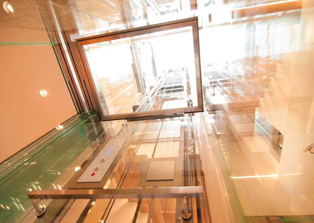
An ambitious home-design team envisioned an all-glass elevator that would provide an uninterrupted vista from the cab for a new home under construction in prestigious West Vancouver, Canada. This vision presented significant challenges and did not seem within reach until they came across UT Elevator. The concept was realized by a cab with all four sides made of clear-glass panels with mitered glass edges within an all-glass hoistway without corner posts.
The key elements of this elevator include: the mitered glass panels without vertical posts, glass touch sensors in lieu of push buttons, fixtures embedded in a clear glass wall, a glass ceiling, a monolithic marble floor and a sliding, frameless glass-door system with an underdriven operator. The aspiring intention was to hide or beautify all the components.
Structure
Since the hoistway walls were all glass, it was decided to run two support columns next to the rails—instead of attaching brackets to a support wall—to minimize visible obstructions. The supports for the customized rail brackets were then welded to the support columns.
The motor was placed above the rails and support columns and below a skylight. The addition of the support columns to the layout made it necessary to spatially reorganize the elevator system and adapt or reorganize many components.
Since the skylight of the home was larger than the hoistway dimensions, the hoistway and motor area was kept as glass to ensure the maximum amount of light passed into the home. The access to the motor area was restricted by customized glass panels and a hinged glass door was designed to be used for future access. Care was taken during the reorganization of the components at the top of the shaft to allow maximum passage of light.
All structural components, including the brackets, rails and other steel members, were powder coated to match the chosen color scheme. The counterweights served as a moving backdrop. The home-design team specified an industrial look without counterweight covers to contrast with the simplified elegance of the cab and to feature them as an interesting piece of art to view from inside the elevator as it passed.
Drive System
The distribution of weight in the car, due in part to a particularly heavy door system and the hoistway constraints for the rail positions, required a unique configuration of drive-system components. A gearless traction system using a 2-hp permanent-magnet AC-synchronous motor was selected for the increased load. The drive and controller were additionally selected and integrated to achieve optimal performance. A 2:1 roping system was used to keep the motor compact and limit energy consumption.
The wiring was run to the hoistway from the controller location through the concrete foundation of the home very early in the process to remain hidden. Once in the pit, the wiring to the drive system and landing locations was run alongside the hoistway in conduits attached to structural columns of the building with predetermined punchout locations. The wiring in the pit was eventually tiled over. Due to the aesthetic constraints to minimize wiring in the shaft, particular care was taken to ensure favorable signal integrity conditions for the motor and encoder cables.
Sliding Glass Doors
The door system is extraordinarily complex for many reasons. It is an underdriven system, meaning that the door operator is on the bottom. The system itself is extremely heavy. The landing-door mechanisms were inset to be flush with the hoistway wall. Since glass was used as frames for both the car and landing doors, and had to be finalized before the tempering process, it could not be modified.
We chose Fermator’s Premium UDD door system, largely due to aesthetics, but also because moving the operator weight to the bottom of the car was preferable. We were the first company in North America to use this particular door system and among the first in the world to field test it. The frameless glass-door panels perfectly complemented the mitered glass cab, and only having a door track at the ceiling level acting as the sill maximized the view from the inside of the cab through the glass. Ironically, the major noticeable difference is that the glass door panels are standard glass with a green tint, whereas the cab glass panels are starfire, which is ultra clear.
The door panels are 17.5-mm laminated and tempered glass with steel attachments for the operator and track that were inset into the glass during the tempering process. Along with the operator, this resulted in a very heavy car-door system and required customization of structural and drive-system components.
The hoistway had not originally been designed to inset landing-door mechanisms. As such, to make room for the mechanisms, the structural beam for one floor of the house had to be cut and reinforced accordingly. The design of the inset mechanisms also had to allow for calibration in all linear and rotational axes. This is especially critical for the underdriven operator, as any imbalance is much more likely to cause binding of the doors than in overhead operators, where gravity is generally a positive impact on leveling. The supplier also emphasized the critical nature of proper door alignment with this system. The design and implementation of a method for the landing-mechanism calibration was a significant installation challenge, even before the actual calibration of the doors.
Additional landing-door calibration challenges were due to the fact that the top track, acting as the sill, was supported by the hoistway glass. The holes cut into the glass were spatially critical, and, as such, the position of the hoistway glass was critical for the correct attachment of the track.
Cab
To meet the customer’s requirement of a cab without vertical posts and mitered glass edges, the top frame was designed to provide the rigidity required without placing critical stress on the glass panels, the glass panels were carefully designed for strength and rigidity, all car-top components were relocated below the cab and covered with a stainless-steel fascia, and an underdriven door operator that left only a door track above was chosen. The top frame had the additional functions of attaching to the sling, supporting a glass ceiling and housing continuous LED lighting.
The cab glass panels are 12.7-mm tempered and laminated starfire panels comprised of two 6-mm-wide panels laminated together. The first challenge was finding a glass supplier willing to make these panels with a mitered edge. It is extremely difficult during the lamination process to line up two panels with a miter and the number of holes, cutouts and notches we had. Dimensions had to have a very low tolerance to ensure all components fit together properly. Our design also had to account for the waving distortion of glass panels during the tempering process, affecting the mitered edges with respect to one another. Once we settled on a supplier that was capable and comfortable with such custom requirements, we ran into a few unique challenges.
One was that the laminating process used was not based on a polyvinyl butyral film, as we anticipated, but a cured resin interlayer with better structural properties that passes less than 1% ultraviolet (UV) radiation. This meant that UV bonding was no longer an option for attaching the car station and phone box to the back of the glass panel. We then had to experiment with tapes, silicones and epoxies as alternatives. All the options had to be “water clear”—virtually invisible—instead of “clear,” and have a long enough set time to ensure precision.
Another unique challenge was that, while we were expecting a chamfer on the miter of the panels, the miter was almost perfect, with a chamfer of about 1/16 in. This meant that installing and transporting the glass panels across the continent was very complicated. Any chip would be noticed, and, since the glass panels were so unique, it would have been very difficult to quickly replace the panel.
The result, however, is a beautifully mitered corner, especially since a water-clear silicone was used to bind the panels together. The water-clear silicone chosen among all the options had the correct balance of rigidity and elasticity to provide support for the glass panels and withstand the vibration and motion of an elevator. Even though having butt instead of mitered joints would have likely halved the complexity of the cab, the commitment to this detail is what makes the cab seem almost transparent from the inside.
Early on, the client team was interested in the idea of glass capacitive touch options instead of traditional buttons. This option calls for a face of glass with circuitry behind it that activates when you touch within a certain area; there is no protrusion or break in the glass face. As this option was not readily available from North American suppliers, several international companies were evaluated. Schaefer was chosen due to the robustness of its RB 42 option and their willingness to customize their options for our design requirements.
The glass for the car station was back painted a pure white and cut for the alarm button, key switch and stop switch. Schaefer was able to accommodate a wider layout of the car station for our logo, and the glass touch buttons and additional components were placed for a simple and elegant result.
Attachment of the car station to the car glass panel was accomplished with a stainless-steel plate to which the car-station back box was affixed. The car-station glass faceplate would protrude in an adjustable manner to be flush with the front of the car glass panel.
Once the car station was designed, we designed a custom phone box, the face of which would be flush with the glass and open with a swing door. The square dimension of the phone-box plate match the width of the car station. The goal was to have the faces of both the car station and the phone box flush with the cab glass panel. The result was worth the attention to detail.
We were very fortunate to be found by a client team that shared our passion for elevators as an art form, and who were willing to tackle such an ambitious endeavor. We chose to take on a number of technical and aesthetic challenges residential elevators have not yet faced with the goal of pushing ourselves further and improving our ability to utilize the advanced manufacturing options now available. Just as the aerospace and auto industries are enthusiastically adopting advanced materials, bonding/fastening methods and cutting-edge fabrication, we are committed to being on the forefront of this magnificent manufacturing revolution we feel is upon us.
Specifications
System type: Gearless traction machine with permanent-magnet AC synchronous motor
Travel: 18 ft., 6-1/4 in.
Door-operator location: Underneath car
Credits
Building owner: Private
Developer: Private
Manufacturer and installer: UT Elevator Inc.
Suppliers: Fermator, Tecnolama, S.A.; SCHAEFER GmbH; Hiwin Corporation; KEB America Inc.; and EMI/Porta Inc.
Get more of Elevator World. Sign up for our free e-newsletter.

