Modelling and Analysis of Guide Rail Brackets and Attaching Parts
May 1, 2013
by Serkan Elmalı, Adem Canda ¸ s, Eren Kayao ˘g lu, C. Erdem Imrak and Sefa Targit
This paper was presented at  USA 2012, the International Congress on Vertical Transportation Technologies and first published in IAEE book Elevator Technology 19, edited by A. Lustig. It is a reprint with permission from the International Association of Elevator Engineers
  (website: www.elevcon.com). This paper is an exact reprint and has not been edited by ELEVATOR WORLD.
Key Words: Guide rails, guide rail brackets, finite element method
Abstract
All kind of elevators have guide rails which guide the car and the counterweight in their vertical travel and stop and hold the car on the application of the safety gear are the most important ones in terms of elevator safety. Guide rail brackets are positioned at regular distances from each other along the rail to fasten the rail to the shaft, and also attached to rail guide and the shaft with the aid of attaching parts (clips and bolts). In this study, guide rail brackets and attaching parts to anchoring the guide rails have been modelled for finite element analysis. Stress and deflection analysis of the guide rail brackets have been executed for different loading conditions and different forces application points between two rail brackets.
1. Introduction
All kind of elevators have guide rails which guide the car and the counterweight in their vertical travel and stop and hold the car on the application of the safety gear are the most important ones in terms of elevator safety. Guide rail brackets are positioned at regular distances from each other along the rail to fasten the rail to the shaft, and also attached to rail guide and the shaft with the aid of attaching parts (clips and bolts). In this study, guide rail brackets and attaching parts to anchoring the guide rails have been modelled for finite element analysis. Stress and deflection analysis of the guide rail brackets have been executed for different loading conditions and different forces application points between two rail brackets. Additionally, the test apparatus has been designed for experimental stress analysis of clips and bolts while applying different loading conditions.
Elevator guide rails are components of elevator systems that define the path along which the elevators ride (Targit, 2002). Under normal circumstances, guide rails simply define the elevator paths that elevators ride along and are assumed to be spared from the loads and forces imposed on the elevator cars (Demirsoz et al, 2005). During elevator travel, the forces will be comparatively low, especially if the car is well balanced and the load is well distributed.
The other loads exerted on the rails will be from safety gear operation under emergency conditions (Targit, 2002). The exerted loads can be very high, depending on safety gear type (Imrak et al 2006).
In practice, the guide rails of the car are fixed in two different ways, at the top of the well (hanging guide rail) or at the pit and guide rail brackets are positioned at regular distances from each other along the rail to support the rail(Koc et al,2010). Buckling loads subjected by the safety devices acting on the guide rails are important parameters in the guide rail calculations. The vertical load (Fk) makes the guide rail buckle in case of descending safety device operation when the guide rails are fixed at the pit. In this case, the guide rail brackets and rail fixing clips are not subjected to extreme loads because the vertical buckling loads are existed at the pit (Kiral et al, 2004).
Considerable research studies have been carried out about elevator guide rail brackets and clips (Koc et al 2010; Kiral et al 2004). Koc has examined stress analysis of guide rail brackets for different loading distribution in different operation situations. Kiral has investigated guide rail and guide rail bracket assembly for different possible loading cases defined in EN 81-1:1998 standard.
In this study, the stress and deformation calculations of guide rail (T90) have been performed according to EN-81 standard during safety gear operation. Guide rail, rail brackets and clips were modeled and finite element model of guide rail assembly was performed. Finite element stress analysis of guide rail brackets and clips was carried out by taking as a reference forces occurred on the guide rail calculations. Studies about this topic, especially about guide rail brackets, are not enough in literature. In this study, it is targeted to overcome the deficiencies that exists taking as a reference some studies done previously.
2. Guide Rail Bracket
For a safe, smooth and comfortable travel, guide rail brackets are the most important components along with guide rails. Guide rail brackets are used for installing the guide rails on the wall and they are usually manufactured by bending sheet metals. While assembling guide rails to rail brackets, different types of clips are used (Koç, 2009).
Although there are currently no standards available for the calculation of clips and brackets, it is crucial to consider safety gear action and particularly forces generated between the clip and the guide rail due to building settlement and expansions caused by temperature variations. The choice of type of bracket will depend on the clip being used, since stresses in the bracket are related to the friction coefficient between the clip and the guide rail (Sanz et al, 2008).
Guide rail bracket and clip design is important as these items provide the means of holding the rails in alignment. For low rise installations, forged steel clips may be used to hold the rails rigid. For installation higher than 20 m, spring clips are favoured because they allow for building compression. All building expand, contract and move to some degree and rail alignment obtained during initial installation should be maintained while this occurs. Again the higher the building and faster the lift, the more critical this aspect becomes (CIBSE Guide D).
During installation, the guide rail must be moved into a proper mounting position before the brackets can be fixed to secure the guide rail in place. The brackets often turn with movement of the guide rail causing an undesirable twisting and locking of the clips against the guide rail. Further, movement of the guide rail for alignment and to compensate for inconsistencies in the guide rail are not easily accommodated with conventional rail clips. Accordingly, it is desirable to develop and design a mounting bracket that is adjustable to accommodate different size guide rails, and that can be movably secured to the guide rail to aid in installation within a hoistway (Koc et al,2010).
3. Finite Element Model
In this study, elevator guide rail calculation performed by taking as a reference a sample elevator project. Forces on the rails applied by the cabin skates were calculated in accordance with accounting principles in TS EN81-1 standard. Accounts from the guide rail forces, stress and deflection values were used as boundary conditions for finite element analysis of the rail brackets. In order to analyse the statical behaviour of the guide rails and the rail brackets during the introduction of safety gear, assembly parameters related to the cabin and the guide rail were given in Table 1 (Elmalı, 2011).
The finite element method is a numerical procedure that can be applied to obtain solutions to a variety of problems in engineering. The accurate prediction of the stresses experienced on the guide rails can be obtained only through the application of computational engineering techniques. Finite element solutions to guide rail and brackets constitute mainly static two-dimensional approaches to the stresses (Moaveni, 1999).
After the calculation of guide rails, finite element stress analysis of the rail brackets will be performed and interpreted. From modelling to analysis results, many programs were used. These programs and the stages are shown in Figure 1.
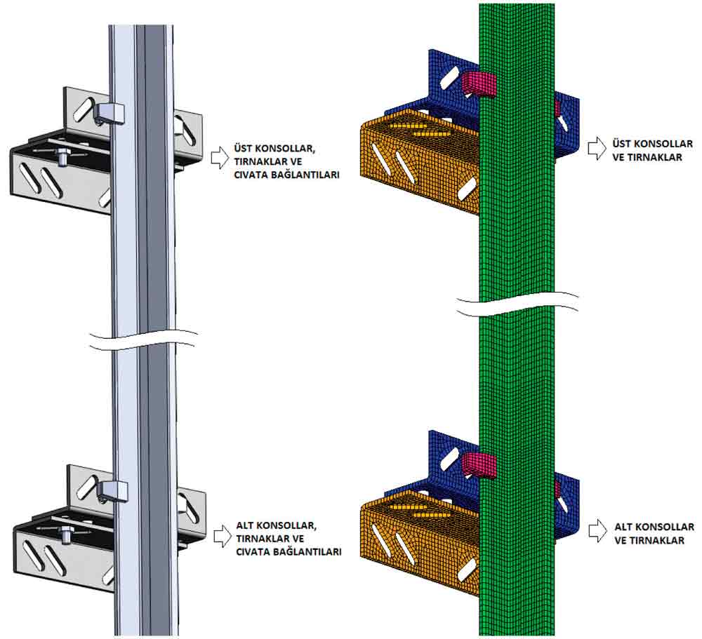
Finite elements network of the guide rails and the rail fasteners modelled in Solidworks was created in Hypermesh. The total length of the rail is 5000 mm and the distance between the rail brackets is 2000 mm. In this study, the full model (both the top and the bottom brackets) was used instead of the half model (only the top or the bottom brackets) in comparison with previous studies. It was not found necessary to create finite elements network of the nuts and the bolts because boundary conditions of the bolts will define during the analysis.
While creating the finite element model of the rails, rectangular prism elements with 8 node points and triangle prism elements with 6 node points were used. Number and types of the elements used in the model were given in Table 2 (Elmalı, 2011).
In this study, the material of the guide rail, guide rail bracket selected depending on the guide rail and rail secure in tab was selected as St37 steel. Elasticity of St37 material was defined in Hypermesh program. The values entered to the program for this definition;
- Material characteristics: Linear isotropic
- Elasticity modulus: 2,1 x 10⁵ N/mm2
- Poisson rate: 0,3
If the parts of assembly move during the analysis or each part shows different behaviour during the analysis, contact properties between the parts must be defined. In order to define the interaction between the unconnected parts working together, all elements were selected and ‘contact’ property between them was defined. After description of friction coefficient between the parts, friction property is taken into account.
Boundary conditions and loads are given in Patran program which is the interface of the Nastran finite element solver program. In this model, 3 different boundary conditions were applied. These are:
a) In this study, it is assumed that guide rails are supported on the bottom of the elevator shaft. For this reason, guide rail used for the assembly was fixed as anchored support from the places connected with connection plates (from the bolt holes).
b) Bolt connection between the rail brackets and the tabs was defined with rigid elements.Similarly, bolt connection between the brackets was defined with rigid elements.
c) In this study, the surface of the bracket, which was fixed on the wall surface, was defined as anchored because brackets werw fixed on the well wallby welding.
Most of structural systems with small deformations (the direction of the force being applied does not change depend on the deformation of the part), elastic materials (plastic deformation is not observed) and static loadings (it does not change depend on the loading time) can be solved with linear static analysis. According to this definition, linear static analysis was chosen for the solution of this system.
4. Numerical and Computational Results
Stresses and deflections on the guide rails, which can be used for the installation of an elevator system with a capacity of 10 passengers in a 16-story building, calculated in accordance with EN 81-1 standard. Rail calculations were made for work status of the parachute assembly for a centrally guided and hanging cabin situation. Slip braking parachute system was used for the parachute system. There is no device to help the guide rails. In this study, centrally guided and hanging cabin situation and related dimensions are shown in Figure 3 (Imrak et al , 2008b).
To analysis stress distribution and deflections of the guide rail bracket and clips, NASTRAN software is selected as a finite element analysis tool. With the analysis of finite element model, which its boundary conditions and loads were given in Patran interface program, stresses and deflections values on the guide rails brackets in Nastran were obtained. The guide rail is supported at the bottom end in the pit and guide rail brackets are positioned at regular distances from each other along the guide rail (Janovsky, 1999). For 800 kg cabin load register, 200 mm distance between centre of gravity of the load register and rail axis, mid-point impact of safety gear on the rail situation, stress values on the guide rail brackets are shown in Figure 4 and, values of deflection are shown in Figure 5.
The highest value of stress was 44,1 MPa and was at a point near the bolt mount points on the bottom brackets. Similar to this, high stresses were generally seen at a region near the bolt mount points. Maximum deflection value was 0,367 mm and was seen on the bottom bracket connected with rail. Maximum deflection points on the bottom brackets and on the top brackets were not at the same points. They were symmetrical. Because reaction forces on the brackets as a result of rail buckling and rail bending are opposite.
Analysis were repeated for different cabin loads and different distances between centre of gravity of the load register and rail axis. The results of this analysis and maximum stress values on the bottom and on the top brackets were given in Figure 6 and Figure 7 in comparison with each other.
Maximum deflection of bottom bracket and top bracket values were given in Figure 8 and Figure 9 respectively in comparison with each other either.
As can be understood in the above graphs, as distance between centres of gravity of the cabin load register and rail axis increase, stress end deflection values increase. As expected, stress and deflection values enhance with the increase of cabin load register.
5. Conclusion
In this study, the stresses and deflections of guide rails are examined by numerical method, on the other hand, rail brackets which are used to support rails to wall are examined by finite element method. In order to show the effects of axis offset an example is given. In this case 2000 mm of vertical distance between guide rail brackets in T70/B guide rail is examined for comparison, finite element method results as given different axis offsets in the figures. The values of stresses and deflections obtained from Nastran are increased with increasing range (xQ). Besides this, high stresses were seen at point of bolt mounts. Maximum deflection points on the bottom and top brackets were not at the same points; but they were symmetric. Because reaction forces on the brackets as a result of rail buckling and rail bending are opposite.
Acknowledgement
This research is a part of work for the project “Modelling and Analysis of Elevator Guide Rail Brackets under Dynamical Loading Condition” funded by ITU Research Fund.
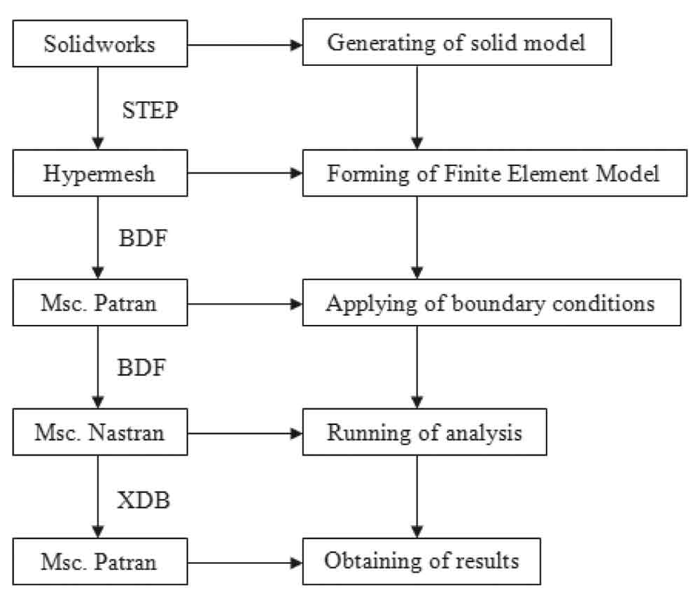
Figure 1: Flow chart for stress analysis of rail brackets 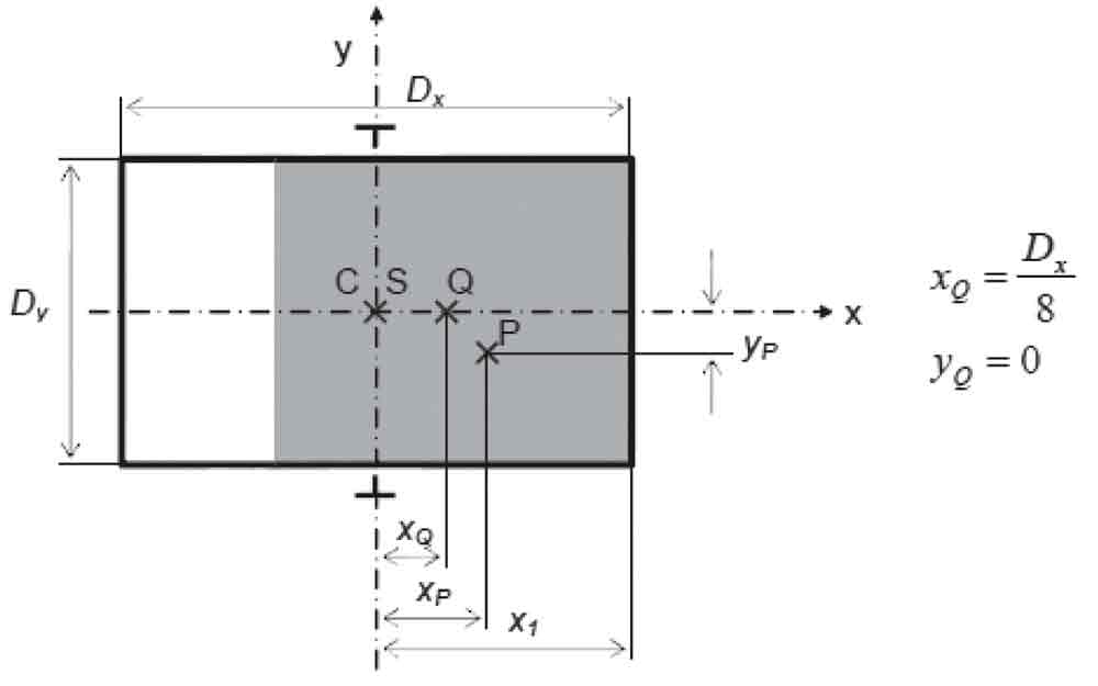
Figure 2: Solid model and finite element model of system 
Figure 3: Load distribution and related dimensions 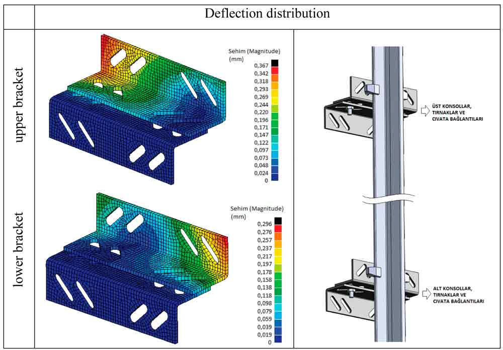
Figure 4: Stress distribution on the guide rail brackets 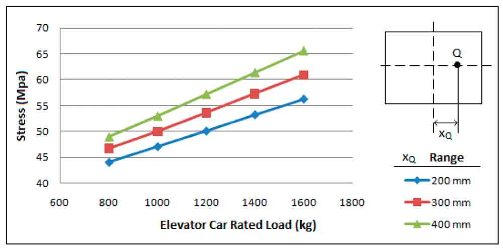
Figure 5: Deflection distribution on the guide rail brackets 
Figure 6: According to axis offset (xQ), distribution of maximum stress of bottom bracket at different loads. 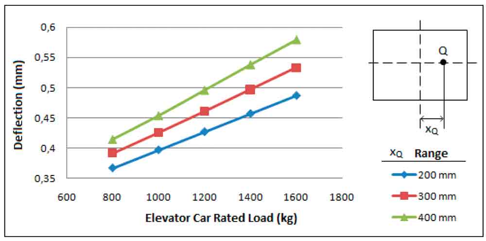
Figure 7: According to axis offset (xQ), distribution of maximum deflection of bottom bracket at different loads 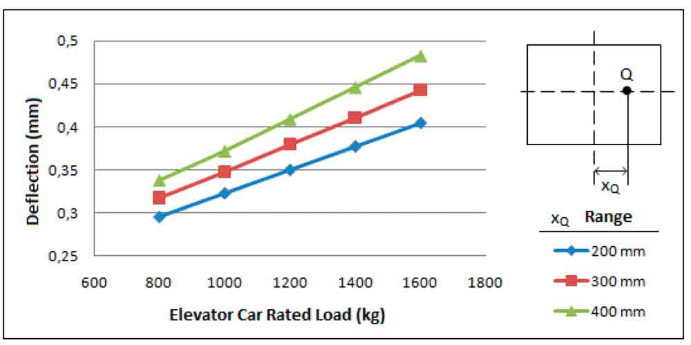
Figure 8: According to axis offset (xQ), distribution of maximum deflection of bottom bracket at different loads 
Table 1: Modelling and design parameters 
Table 2: Element types and number in finite element model
REFERENCES
Demirsöz, R, Imrak, C.E., Targıt, S. (2005). Finite Element Analysis of
Elevator Guide Rails during Safety Gear Operation, Elevator Technology 15, Proc. of ELEVCON’ 2005, pp.41-50.
Elmalı, S (2011). “Stress Analysis of Guide Rail Anchors”, MSc. Thesis, ITU, Istanbul.
Imrak, C.E., Bozdag, E., Sunbuloglu, E., Toprak, T., Targıt, S. (2006). Experimental Stress Analysis of Guide Rails, Elevator Technology 16, Proc. of ELEVCON’ 2006, pp.111-119.
Imrak, C.E., Bedir, S., Targıt, S. (2008a). Investigation of Stresses on Guide Rails and Safety Gears, Elevator Technology 17, Proc. of ELEVCON’ 2008, pp.111-119.
Imrak, C.E., Bedir, S., Kayaoğlu, E. (2008b). Finite Element Modelling
& Stress Analysis on Guide Rails During Safety Gear Operation, Symposium in the Mechanics of Slender Structures MoSS 2008, Baltimore, USA.
Janovsky, L. (1999). Elevator Mechanical Design, the third edition, Ellis Horwood Publ., London, 322 pp.
Kiral, Z., Tavaslioglu, S. (2004), Computer Aided Analysis of The Guide Brackets in Different Loading Cases Including Safety Device Operation, Elevator Technology 14, Proc. of ELEVCON’ 2004, p.155-162..
Koç, S., Imrak, C.E, Targıt S. (2010). Design Parameters and Stress Analysis
of Elevator Guide Rail Brackets, Elevator Technology 17, Proc. of ELEVCON’ 2008, pp.177-185.
Moaveni, S. (1999). Finite Element Analysis: Theory and Application with ANSYS, Prentice-Hall, New Jersey.
Sanz, J., Fernandez, J. E., (2008). Importance of the Riding Path in Elevator Safety, Elevator Technology 17, Proc. of ELEVCON’ 2008, pp.343-353
Targıt, S. (2002). Elevator Guide Rails, Installation and Alignment, Elevator World September 2002, pp.102-105.
Get more of Elevator World. Sign up for our free e-newsletter.


