This History article examines early, comprehensive G.A.L. materials that guided installation and maintenance.
In the 1950s, the resources required for elevator modernization often supported future maintenance. This dual use of technical materials is illustrated by the examination of a packet provided by G.A.L. Electro-Mechanical Service of NYC to Elevator Maintenance Co., Ltd. of Los Angeles in 1956. The companies, both founded in 1927, represent the diversity of the vertical-transportation industry. G.A.L., founded by Herbert Glaser, Jack Ambramowitz and Harold Leon, specialized in door operating systems, interlocks, switches and similar devices. Elevator Maintenance, founded by Anthony A. Montapert, offered a range of services including complete system design, installation and maintenance. In December 1956, Montapert ordered door operators and interlocks for an elevator in the Livingston Apartments in Long Beach, California. In addition to supplying the equipment, G.A.L. furnished a comprehensive set of materials intended to guide installation and maintenance.
The packet included a coversheet, eight drawings, a wiring diagram, dimension tables, and installation and maintenance guidelines. The cover sheet listed a G.A.L. order number (69466), customer order number (14188) and customer job number (20103). It also featured several fill-in-the- blank sections that specified the order’s details:
- “Type: Two Speed “
- Door Opening: 36 “
- Hand: Right
- “No. of Hatch Openings: 5 “
- No. of Car Openings: 1 “
- Date: 12-14-56”
The drawings were smaller versions of full-sized technical drawings, with each featuring a title block that identified the contents, drawing number, date, etc. The eight sheets of drawings touched on all aspects of the proposed installation:
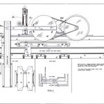
- “Master Door Operator for Two Speed Doors,” Drawing No. L-5214-A ( June 21, 1950)
- “Type M.O. Interlock Arrangement,” Drawing No. L-5430 (December 30, 1953)
- “Mounting Details for Door Operator — on Metal Cab,” Drawing No. M-5164-A (April 6, 1950)
- “Hanger Header Details & Car Door Drillings & Reinforcement for Master Door Operator,” Drawing No. 5163-L (August 24, 1950; revised April 4,1954; handwritten note noting revision on October 11, 1956)
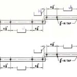
- “Two Speed Hatch Door Hanger Installation Details,” Drawing No. L-5225-A ( July 13, 1956)
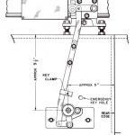
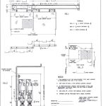
- “Spring Closing Linkage for Two Speed Doors (New Style),” Drawing No. L-5219-A (August 10, 1950; revised April 28, 1954)
- “Button Station Cutout Dimension Table,” Drawing No. 5227-A (February 2, 1954)
- “Cutout for Key Box,” Drawing No. SK-231 (undated)
The drawing dates, from April 1950 to October 1956, suggest both manufacturing continuity and a pattern of improvement over time. The quality of the drawings serves as a reminder of the precision possible in hand drafting and the high level of visual detail provided to guide installation and future maintenance (Figures 1-4).
The drawings also employed a format that effectively met the diverse needs of potential clients. Because G.A.L.’s door operators and interlocks were adaptable to a wide range of settings — for example, they could be applied to door openings 29-53 in. in width — the drawings needed to employ a format that allowed for flexible use. To meet this demand, the draftsmen placed open boxes or blank spaces on critical dimension lines. Letters that referenced numbers found in dimension tables that accompanied the drawings would be added to these spaces (Figure 5). This allowed G.A.L. to furnish one set of materials designed to meet diverse installation types and settings. The materials sent to Elevator Maintenance included four dimension tables: one for Drawing No. L-5163-L, two for Drawing No. L-5225 and one for Drawing No. 5219-A.
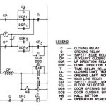
The one-page wiring information sheet for the master car panel and door operator included four diagrams: a three-phase AC operator motor, a car panel operator in connection with swinging hoistway doors, a master door operator with sliding hoistway doors (safety edge — parked open) and a master door operator with sliding hoistway doors (safety edge — parked closed). The sheet also included descriptions of the various systems’ operation. The level of detail provided is illustrated by the notes that accompanied the wiring diagram (Figure 6) of the master door operator with sliding hoistway doors (safety edge — parked closed):
“With this circuit, the safety edge equipped car panel and hoistway door will remain in the closed position while the elevator stops at a landing. The time relay T and the auxiliary closing relay CP are energized, and the closing of a direction relay will shunt the closing limit contact on the operator, energizing the latter and lifting the retiring cam. The mainline relay becomes energized, breaking contact ML, opening the time relay circuit and rendering the safety edge relay circuit OP inoperative. Time relay T opens contact T, which was shunted by direction contact 2 to keep the auxiliary closing relay CP energized, holding in contact CP1. The closing relay circuit will remain energized until the direction relay drops out.
“Opening the direction relay deenergizes the closing relay and the auxiliary closing relay circuits by direction contacts 1 and 2. Opening these relays closes contact C and CP2 in the opening relay circuit, energizing same and opening the doors. As the doors arrive in the full open position, the opening limit contact on the operator breaks, deenergizing the opening relay circuit.
“Contact O is being closed by this action, energizing the time relay T, which, in turn, energizes the auxiliary closing relay CP, making contact CP1 in the closing relay circuit. The doors now close, and, as they arrive in the closed position, open the contact on the operator closing limit.
“Actuating the safety edge or pressing the opening button during the closing cycle energizes safety edge relay OP, breaking contact OP in the auxiliary closing relay circuit and contact CP1 in the closing relay circuit. Contact C and CP2 are now made and the opening relay energized. The doors now open fully before they can close again.
“Pushing the hall button on the floor where the elevator is at rest will have the same e.ffect as operating the safety edge or pressing the door opening button.
“Pushing the door closing button, while a direction switch is set, energizes the auxiliary closing relay CP, closing hold-in contact CP3 before the time relay starts operating.”
This information would have proven useful in both installation and troubleshooting during routine maintenance.
The G.A.L. packet also included information on the “Final Adjustments of Oil Check on Two Speed Power Operator.” In a similar manner to the information that accompanied the wiring diagrams, the oil check adjustment instructions provided a detailed operational description:
- “The function of the spring that is approximately 5.5” to 6” long on the two speed oil check bracket assembly is to bring the operator oil check back to its original position — that is, the roller assembly down. This, as a rule, is sufficient to bring the operator arm out of the straight horizontal position to permit the opening of the doors in case of power failure. If the spring tension is insufficient to do this, the shorter helper spring can be adjusted to accomplish this.
- “For actual adjustments of the Power Door Operator, the tension in the operator chain should be adjusted. The chain should not be drawn tight but should have as little play as possible. Next, make the oil check strong (see decal on check barrel) and close the doors under power. You will see that there will be a deflnite hesitation in the hatch door, as this hesitation and bounce may not be seen, since the doors are lapped behind the daylight line. To eliminate the bounce in the door, soften the check accordingly. You will notice that there will still be a hesitation in the door. The object now is to get the point of hesitation of the door to occur simultaneously with the door arriving at the strike jamb bumper by raising the pickup roller. To raise the pickup roller, screw the rod that contains the longer spring on the check bracket assembly into the forked turnbuckle. As the roller is raised, you will note that the point of hesitation comes closer to the strike jamb.
- “For park closed operation, the close limit should be adjusted so that when the door closes, it will not compress the long spring on the check bracket assembly to such an extent as to cause the arm to be forced back. You will note that if the limit opens too late, this action will occur. We have found that the operator can be adjusted for park closed operation so that the hatch door will be within the door rabbit. The car door will stop approximately 3/4” from its strike jamb bumper, and the strike edge of the car door, if you are standing in the car, would be visible. However, we do not believe this is detrimental, as for park closed operation, no one would ordinarily be in the cab. The opening limit should be set so that when the safety edge is activated, the door will open within 2” to 3” of full opening. If the door slams in opening, the speed of the operator may be too fast, or the friction brake, which is mounted on the mounting bracket of the intermediate sheave, may have to be adjusted.”
A similar level of detail was found in the information contained in a sheet simply titled “Oiling,” which offered straightforward advice regarding when oiling was required and how it could be used to address operational problems:
“Once a month:
On operator chain — Apply light machine oil with brush and agitate chain to make certain oil will penetrate into bushings. Wipe o.ff excess oil.
“Once a year:
Replace all oilers on hanger sheaves of car and hoistway doors. Take oil checks apart, clean and reflll with fresh light check oil. “Oil needed if squeaks develop:
Two drops in oil cup of brake on belt pulley chain
One drop in guide bushings spring rods of operator emergency release
One drop in guide bushings on spring rods of hoistway door closers
“To quieten (not a necessity):
One drop of oil on all joints on lock release and keeper One drop of oil on all joints on car door clutch
“Caution: Make certain to wipe o.ff all excess oil. Remember oil collects dust.”
The material examined for this investigation was found inside a G.A.L. “perpetual catalog” published in 1954. So-called perpetual catalogs were published in binders with metal prongs that permitted easy substitution of new materials and, in this case, the addition of specific project materials. The location of this information, along with the technical material contained in the catalog, provided Elevator Maintenance with a wealth of additional information. The full catalog will be the subject of a future article. The full G.A.L. packet for this project is available as an Online Extra this month.
- Figure 1: G.A.L. Drawing No. L-5214-A, “Master Door Operator for Two Speed Doors” (June 21, 1950)
- Figure 2: Detail from G.A.L. Drawing No. L-5430, “Type M.O. Interlock Arrangement” (December 30, 1953)
- Figure 3: G.A.L. Drawing No. L-5219-A, “Spring Closing Linkage for Two Speed Doors (New Style)” (August 10, 1950; revised April 28, 1954)
- Figure 4: G.A.L. Drawing No. L-5225-A, “Two Speed Hatch Door Hanger Installation Details” (July 13, 1956)
- Figure 5: Example of G.A.L. drawing referencing system
- Figure 6: Wiring diagram for G.A.L. Master Door Operator with sliding hoistway doors ( safety edge — parked closed)
Get more of Elevator World. Sign up for our free e-newsletter.
