Motor Drive and Control
Apr 1, 2019
An introduction to major elevator drives, including history, fundamentals and the future
This article is excerpted from your author’s upcoming book, The Elevator: From Basics to Calculus, which discusses key elements in elevator systems, focusing on the topics of motor drives and control, traffic analysis, and ropes and traction. It is intended to provide quick reference for experienced professionals and basic knowledge of the elevator systems for those new to the industry Editor
This article is excerpted from your author’s upcoming book, The Elevator: From Basics to Calculus, which discusses key elements in elevator systems, focusing on the topics of motor drives and control, traffic analysis, and ropes and traction. It is intended to provide quick reference for experienced professionals and basic knowledge of the elevator systems for those new to the industry Editor safety (i.e., broken ropes), the solution of which was only available some 2,100 years later. In 1852, Elisha Graves Otis invented the primitive safety gear, which could lock the elevator cab in place when the hoisting ropes were broken. He publicly demonstrated it one year later at the New York Crystal Palace in New York City, the city in which the world’s first safe elevator was installed in 1857.
Learning Objectives
After reading this article, you should:
♦ Have been introduced to the history of development of elevators and the basic structure of a traction or electric elevator drive
♦ Understand the fundamentals of a traditional AC-2 drive
♦ Understand the fundamentals of a DC drive (both MG and TL types)
♦ Understand the fundamentals of an ACVV drive and the contemporary ACVVVF drive
♦ Have been introduced to other drives, including hydraulic, PMSM, reluctance- motor and linear-induction-motor drives
The basic structure of an elevator consists of a cab or car with car doors associated with the cab and with landing doors at the landings. When the car arrives at a floor, the landing doors are opened and closed by the car doors, which are powered by door operators (basically, motors with mechanical links). Passengers travel between floors by boarding and exiting the cabs that move up and down by hoisting ropes, hydraulic plungers, special installations like rack-and- pinion drives, or the more advanced linear machines of the future.
Most elevators move by hoisting ropes that lay on grooves of drive sheaves mechanically driven by motors via a brake and/or a worm-gear box (Figure 1). This is called a traction elevator: one end of the hoisting rope is fixed to the cab, while another end is fixed to the counterweight. Conventionally, there are, in general, three types of motors used in elevator systems: AC, DC and a hybrid between the two.
AC-2 Motor
The AC-2 motor is a primitive motor drive popular at least half a century ago for low-speed elevators. It is usually coupled with a worm gear to reduce speed and increase driving torque. A standard three-phase induction motor carries one set of three windings placed 60° geometrically side by side on the stator (Figure 2). The three-phase currents flow through the three sets of windings (Figure 2: “1”-“2,” “3”-“4” and “5”-“6”). During stage “a),” a current at conductor “1” flows out of the paper (represented by a dot), and that at conductor “2” flows into the paper (represented by a cross). The magnitude of current along winding “1”-”2” is maximum, as indicated by a solid black dot and a big cross.
Using the famous “right-hand grip rule” (thumb pointing to the direction of the magnetic field with other fingers showing the flow direction of current) shows the resultant magnetic field pointing rightward. The magnetic field produced by points “3”-“4” go up-right, while that produced by points “5”-“6” points down-right. So, the resultant magnetic field still points to the right. As time goes by, during stage “b),” the resultant magnetic field is pointing down-right and so on. That shows the generation of a rotating magnetic field with a constant amplitude by a three-phase electric supply. According to Faraday’s law of induction, when the rotating magnetic field cuts the rotor of the motor, an electromagnetic force and, thus, a current is induced. This induced magnetic field goes against the field from the stator. The two interacting magnetic fields result in a rotating torque. This is because the one produced by the stator is rotating, and the rotor is pushed to rotate, because the stator is stationary.
It can be shown that the rotating speed, also called the synchronous speed, Ns (in rpm), of the stator’s magnetic field is directly proportional to the frequency, f (in Hz), of the electric supply and inversely proportional to the number of poles, p, of the windings:
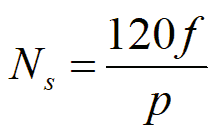
The simplified stator shown in Figure 2 is a two-pole machine, i.e., p = 2. So, if f = 60 Hz, Ns = 3,600 rpm = 60 revolutions per second. Figure 2 shows that in one cycle of 1/60 s., the field rotates one circle around the stator. In other words, in 1 s., the magnetic field can revolve 60 circles. In a practical motor, the minimum value of p is usually equal to 4 or 6. Current is induced in the rotor by electromagnetic induction to produce a magnetic field to counteract the stator magnetic field (as explained above). So, the rotating speed of the rotor must be lower than that of the stator magnetic field. The two rotating speeds are identical to each other only under the condition when there is zero resisting torque on the rotor side, which is only an ideal case. Therefore, Ns is also called the synchronous speed of the motor, which is the theoretical limit.
In the induction motor of an AC-2 elevator, there are two different sets of three-phase windings: for example, one with p = 6 and one with p = 24. The rotating speed of the rotor when the low-pole windings are energized is, therefore, four times that when the high-pole windings are energized. During normal operation, the low-pole windings are normally used for acceleration and rated speed operation, while the high-pole windings are mainly used for deceleration and during maintenance when someone is on the car top. To reverse the direction of rotation, two of the three phases of the supply voltage are interchanged with each other, and the motor rotates in an opposite direction.
DC Motor
AC-2 motors were used in the old days for low-speed elevators with the help of a worm gearbox. For high-speed elevators, however, DC motors were used. This is because DC motors usually have higher starting torque than AC motors. A cross-section of the DC motor is shown in Figure 3. DC passes through respective field windings on the stator poles to produce a magnetic flux around the pole, Φf. There are conductors on the surface of the rotor where another DC current passes through them, thus producing an armature magnetic flux, ΦA around the pole. Φf and ΦA are so arranged that they never coincide with each other, i.e., there is always an angle of separation between them. These two magnetic fluxes interact with one another, usually by repulsion, to produce a torque that depends on the strength of each flux and the angle of separation between them.
Since current must flow into the rotating rotor, a mechanism, commutator and brush are needed to facilitate that. The brush, usually made of carbon, is stationary with the stator, while the commutator rotates with the rotor. Then, current can pass from the power supply to the brush to the commutator and, finally, to the rotor winding. The direction of the force on the rotor conductor can be determined by the famous Fleming’s “left hand motor rule”: the first finger of the left hand points to the direction of the field flux produced by the stator, the middle finger points to the direction of the current flow along the rotor conductor, the thumb points in the direction of the resultant force produced. This easily shows that the final torque of Figure 3 is in the counterclockwise direction, in line with the repulsive force between ΦA and Φf. It should be noted that, with the help of the rotating commutator, both the field flux from the stator and the armature flux from the rotor remain generally unchanged. Therefore, the torque is continuous.
While there are basically two ways to produce a power supply for the stator windings of a DC motor, the rotor flux is supplied by the same general principle. The more primitive method was called the Ward-Leonard or motor-generator (MG) set (Figure 4) in which a three-phase inductor motor is mechanically coupled with a DC generator. The rotating speed of the induction motor is rather constant. The DC supply voltage from the generator is variable (by changing its field current). The mathematical model of a DC motor will be discussed in a forthcoming article. The adjustable supply voltage is applied to the DC motor of the drive. A higher voltage results in faster rotation, and vice versa. With a high starting torque, this type of drive is appropriate for high-speed elevator applications.
Considering modern alternatives, it is too bulky to install MG sets and too labor intensive to maintain them; a relatively modern approach developed in the early 1970s is to replace the MG set by two power electronic converters. Called a “Thyristor-Leonard (TL) set,” each convertor consists of six thyristors (silicon- controlled rectifiers [SCRs]) (Figure 5). Again, a variable DC supply can be generated by properly firing the six SCRs to convert the three-phase AC supply to DC, which is further applied to the DC motor (“M” in Figure 5) through a choke to smooth out the pulsating effect. A thyristor, or SCR, is like a directional valve for electric current. It has three terminals: the anode (“A” in Figure 5), cathode (“C in Figure 5) and gate (“G” in Figure 5).
Under a normal condition, the valve, or the SCR, is closed and no current can pass through it. When an electrical signal is applied to the gate, “G,” of the SCR, it is turned on and presents a very low resistance to the flow of current. This is along the direction of the arrow symbol, from “A” to “C,” but never from “C” to “A.” When a current is passing through an SCR, there is a low positive voltage across it, with voltage at “A” slightly higher than that at “C.” To turn off the valve, the signal to the gate must first be turned off, followed by reducing the current through the SCR to zero by other means and, finally, by applying a small negative voltage, called “reverse bias,” across the SCR. This process makes voltage at “C” a little higher than that at “A” and is called “commutation.” So, it is ideal to use SCRs for rectifying AC to DC, because when the AC changes from the positive to negative cycle or vice versa, the relevant SCR is automatically cut off.
AC Variable Voltage (ACVV) Drive
Up to now, it seems that the DC motors could serve both high- and low-speed elevators well. However, DC motors have intensive maintenance requirements, as the brush/commutator arrangement has to be serviced from time to time. Also, the cost of DC motors is much higher than that of AC motors of the same rating. The rotor of an AC motor is just a squirrel cage or with some short-circuited windings without any connection to the stationary external environment. But, AC-2 is certainly not the solution, as speed cannot be freely adjusted.
A common sense is that if the voltage of the three-phase power supply to an AC induction motor as shown in Figure 2 varies, the driving torque varies at the same time, and there is, thus, a subsequent acceleration or deceleration. It is called an AC Variable Voltage (ACVV) drive. A simple relationship between the driving torque, ΓD, measured in Newtons, and the load torque, ΓL, for all types of motors is shown in Equation 2, where J is the combined equivalent moment of inertia, measured in kgm2, of all the mechanical rotating parts, and ω is the instantaneous rotating speed of the rotor, measured in radians per second. One complete circle of 360° is equivalent to 2π radians.
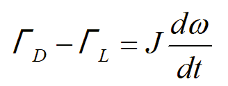
It should be noted that the moment of inertia includes all rotating parts, such as the rotor, bearings, shaft, sheave, etc. However, the load torque includes the friction on the bearings, as well, not just the counterbalancing torque from the elevator car and ropes. Figure 6 shows the principle of operation of a typical ACVV drive. The torque-speed curves of three different voltages applied are shown where Vs > Vs1 > Vs2. Tst is the starting torque under Vs; Tst1 is the starting torque under Vs1 and so on. TL is the load torque. In practice, the load torque of elevators is rather flat, as it is quite independent of the speed of operation. ω is the steady-state speed (in radians per second) under Vs, ω1 under Vs1 and so on. ωs is the synchronous speed (in radians per second), which is conceptually identical to Ns but measured in different units. Nm or ωm, is the instantaneous speed of the motor. The speed of operation gradually decreases as the voltage of the supply decreases; thus, the term “ACVV.” However, the range of speed control, as shown in Figure 6, is rather limited. Furthermore, there is a parameter, S, shown in Figure 6. It is called “slip,” which is defined as:

Hence, S = 0 at synchronous speed, and S = 1 when the rotor is stationary. When the mathematical model of the AC induction motor is analyzed, S is usually used instead of ω or N. The normal operating value of S is around 5%.
ACVV and Variable-Frequency (ACVVVF) Drive
Although an ACVV drive can adjust the speed of operation of an elevator and require less maintenance than a DC drive, there are three main issues. First, as discussed before, the speed control range is relatively narrow. Second, the load torque must be much lower than the maximum torque under the rated voltage supply. Third, it is not energy conservative, as the energy loss is quite high. Therefore, as of 25 years ago, ACVVVF drives have dominated the market, to the point that AC-2, DC and ACVV drives can no longer be easily acquired.
As the name tells, both the voltage and frequency of the supply are adjusted. Figure 7 shows the torque-speed curves of a typical ACVVVF drive. The curves toward the left side belong to a lower voltage, V, and a lower frequency, f, with V/f usually being kept constant, though with exceptions. For example, if the rated
three-phase voltage is 480 V and rated frequency is 60 Hz, V/f is around 8. As shown in Figure 7, the load torque is quite constant for an elevator. When the V or f continues to increase, the speed continues to increase, as well, until the rated value is achieved. This is a very good speed control model. Figure 8 shows the circuit diagram of the drive. The regular three-phase supply is first rectified by a converter to DC on the DC bus, which is further converted back into AC by the inverter with free adjustment in V and f. The components used in the converter are power diodes, while those used in the inverter are usually insulated-gate bipolar transistors.
When the elevator is descending with a car load heavier than the counterweight load, the control system must try to brake the elevator. At this moment, energy is fed back from the motor to the inverter and DC bus. Such energy could not go back to the
three-phase supply due to the directional characteristics of the power diodes, and it must be dissipated somewhere. The braking resistor is essential in consuming the energy to make sure the whole drive is safely operating. This is a safety concern and certainly not desirable from an energy-conservation point of view. So, the idea of “regenerative braking” is popular so that energy can be fed back to the power grid via a different route.
The operating principle in Figure 7 is called “scalar control,” which is good for speed control under a steady-state, low-speed, open-loop condition. Here, “open loop” refers to the nonexistence of current feedback control, not speed feedback, which is always essential in elevator operation.
Induction motors are superior to DC motors in size, weight, inertia, cost and speed, but DC motors are superior in ease of control. If precise dynamic closed-loop control providing comfortable acceleration and deceleration and very low speed leveling, etc. are needed, flux vector control of such an ACVVVF drive is necessary. The basic idea of “flux vector control” is a series of mathematical transformations where the three-phase (electrically 120° apart) voltages and currents are mathematically transformed to a two-phase (electrically 90° apart) system. These are called direct-axis vectors and quadrature-axis vectors, respectively. Since the two phases are now perpendicular to each other, there is no mutual influence between them, and they can be controlled independently. One vector is responsible for the flux component (analogous to the field produced by the stator in a DC motor), while another is responsible for the torque component (analogous to the armature field produced by the rotor in a DC motor).
In a three-phase system, unless a totally balanced situation can be maintained, anything different on one phase has some impact on the other phases. So, the “scalar control mode” requires a balanced operation all the time. In this way, torque control under “flux vector control” with fast changes and adaptations can be conveniently achieved. Under this category, there are two branches: field-oriented control and direct torque control.
Hybrid Motor: PMSM Drive
When an induction motor is utilized, even when flux vector control is adopted, the rotor magnetic field still must be produced by the stator magnetic field, resulting in a slower and weaker response. If the rotor magnetic field can be generated autonomously but not by the way of the brush/commutator as in a DC motor, the torque-to-motor size ratio can be greatly increased. This is the technology of the permanent-magnet synchronous motor (PMSM). In these motors, the rotor windings or bars are replaced by permanent magnets, with the following advantages:
- Elimination of copper loss
- Higher power density and efficiency
- Low rotor inertia
- Possibility of a larger air gap because of larger coercive force densities
Of course, there are also disadvantages, as follows:
- Loss of flexibility of rotor field flux control
- High cost of permanent magnets with high flux density
- Degradation of magnetic characteristics over time
- Loss of magnetization when operating temperature is above Curie temperature.
At temperatures below the Curie point, the magnetic moments are completely aligned within magnetic domains in ferromagnetic materials. Above such temperature, such alignment is gradually destroyed. Having all these cons, they are still gaining popularity in modern elevator applications because of high torque-to-size and torque-to-weight ratios, as well as the hope of reductions in costs with the possibility of replacing rare-earth metals with artificial metals. Also, the permanent magnets can be suitably arranged to form axial-field motors. In conventional motors, the magnetic fields are usually perpendicular to the axis of rotation of the rotor. In axial-field motors, the fields are all parallel to the axis of rotation, producing a very thin appearance. This makes them suitable for machine-room-less applications (Figure 9).
Another kind of permanent-magnet motor is the brushless DC (BLDC) motor, but this type is not popularly used in the elevator industry. By replacing a conventional motor with a PMSM one of the same rating, an average energy savings of at least 25-30% can be achievable. For applications with very high speeds, say, 15 mps (3,000 fpm) or above, it is impossible to use conventional motors, and PMSM becomes the only choice.
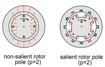
Figure 10 shows two kinds of PMSMs: both are two-pole-pair machines but different in their rotor design. The magnetic fields generated by the rotor are all from permanent magnets attached to it. A rotating magnetic field at the stator is generated by a three- phase supply of variable frequency and variable voltage, quite sinusoidal with the waveform. This is like the converter/inverter arrangement in Figure 8. It is called “hybrid” because the magnetic field at the rotor is constant in magnitude, analogous to that of a DC motor. When the stator field is rotating, the rotor field follows by attraction or repulsion and, thus, the physical rotor. For BLDC motors, even the stator field is not purely sinusoidal.
Hydraulic Elevator
Although traction elevators have been dominating the market, hydraulic elevators are still installed, and their technology has been modernized during the recent decade. To be simple, a hydraulic elevator consists of a cylinder filled with oil with a plunger/ram/ piston on top of the oil. The plunger supports the elevator cab or, in some designs, pulls a set of hoisting ropes that suspend the elevator cab. When oil is injected under the plunger, the cab rises, and when oil is released, the cab falls. The oil pump with its motor is usually submerged in the oil tank, coordinating with the oil valve for the operation of the elevator. Oil is an insulator, and the submerged motor can function normally. Since slight leakage of oil and change in oil temperature are sometimes unavoidable, automatic releveling takes place from time to time. Thus, the pump may operate even when the cab stops at a floor. In general, a hydraulic elevator consumes much more energy than a traction elevator. Very often, the machine room of a hydraulic elevator must be air-conditioned. Since the movement of the elevator cab is based on filling and releasing oil to and from the cylinder, a simple AC induction motor that drives the pump is good enough.
In the last decade, research has been conducted to turn hydraulic elevators green by conserving energy. That is achieved by introducing inverters to the motor drives, such as with ACVVVF hydraulic elevator drive. Furthermore, when oil is released to lower the elevator cab, the pump motor is arranged appropriately to extract energy from the flowing oil back to the power grid.
Reluctance Motors
The stator structure is nearly identical in the types of AC motors mentioned before. Their differences are mainly in the rotor. The basic idea is to let the rotor follow the rotating magnetic field generated by the stator, either by electromagnetic induction or by permanent magnets. There is one more means or approach, which is to design the rotor in such a way that the magnetic flux from the stator can easily penetrate the rotor when the rotor is at a particular position relative to the field. In other words, the rotor can automatically align itself where there is minimum reluctance to the stator field. So, when the stator magnetic field rotates, the rotor follows. This is the development of “synchronous reluctance motors.” With proper design, the performance of a reluctance motor can approach that of an induction motor, although the reluctance motor may be slightly heavier and has a lower power factor. Power factor is an electrical parameter used to measure how well a load utilizes the power supply, and varies between 1 and 0. A value higher than 0.85 is considered normally acceptable.
When the stator is similar to that of an AC induction motor, there is no magnet or squirrel cage in the rotor (Figure 11). Field-oriented control is needed to drive such a motor. The iron laminations in it are separated by nonmagnetic materials, thus increasing the reluctance flux in the quadrature axis. However, the use of such motors in elevator systems is still under research.
Linear Motor Drive
Since the invention of elevators in the late 19th century, the very fundamental design has not been changed at all. That is, the number of elevators in one vertical hoistway or shaft has been usually one and mostly up to two. We have double-deckers when two cabs are hinged together, one on top of the other, serving two consecutive floors. This is virtually equivalent to one big cab with double capacity. This conventional design of one to two elevators per hoistway could be considered a waste of the hoistway by, for example, imagining that there is only one train moving on a long rail. Although the first thyssenkrupp TWIN system was put into operation in Germany in 2003 where two cabs can move independently, one always on top of the other, the technology still limits the number of cabs to two. Whenever ropes or plungers are used, the number of elevators cannot go beyond that limit.
Buildings are getting taller and taller, with a height of 500 m (1,640 ft.) or above being common. It would be perfect if we could have, say, four to five cabs running along the same shaft at the same time, serving passengers at different zones of a tall building. To realize this dream, elevator cabs must be able to move by themselves, like trains on rails. Thus, we must do away with ropes and plungers. The use of linear motors is not new, as we can find applications in the railway and conveyor industries. There are linear synchronous motors and linear reluctance motors, as well. In the elevator industry, we foresee the major application in the near future as being linear PMSMs. The idea of employing linear motors in elevator systems was first proposed by Otis and Mitsubishi in the early 1990s.[1] Since then, no practical model had been put into real operation due to safety concerns: Nobody could take the risk of a power failure as the cab is floating in the air without attachment when a linear synchronous motor is employed. The preliminary demonstration model of thyssenkrupp’s MULTI system (ELEVATOR WORLD, February 2015) showed a linear motor within the guiding equipment installed on the back of each elevator cab. This lifts the cab not only up and down, but also right and left. The cab runs on a rail, providing a high safety margin.
Learning-Reinforcement Questions
Use the below learning-reinforcement questions to study for the Continuing Education Assessment Exam available online at www.elevatorbooks.com or on p. 117 of this issue.
♦ Why were AC-2 but not AC-1 motors used in the old days?
♦ Why aren’t DC motors used in new elevator installations?
♦ What are the pros and cons of using ACVV drives in elevator systems?
♦ What is the major difference of an ACVVVF drive under scalar control and vector control, respectively?
♦ What drive would you recommend for an installation that serves a building of four stories (50 ft. tall) using a rated
speed of 100 fpm?
- Figure 1: A typical geared traction drive; from CIBSE Guide D, courtesy of Otis
- Figure 2: A rotating field generated by three-phase currents inside an induction motor
- Figure 3: The operating principle of a DC motor
- Figure 4: The operating principle of an MG DC drive
- Figure 5: A TL DC drive
- Figure 6: Torque-Speed curves of an ACVV drive
- Figure 7: Torque-speed curves of an ACVVVF drive
- Figure 8: Circuit diagram of a typical ACVVVF drive
- Figure 9: A transition from a conventional motor to a PMSM (“New Traction Machine for MRL Elevators,” EW, April 2005)
- Figure 10: Internal structure of a PMSM
- Figure 11: Rotor layout of a synchronous reluctance motor
Reference
[1] Janovsky, L. Elevator Mechanical Design, IAEE, Ellis Horwood, New York, Chapter 1 (1993), available at www.elevatorbooks.com.
Get more of Elevator World. Sign up for our free e-newsletter.


