Replacement of existing passenger and goods passenger lifts in existing buildings
by Pravin M Tipnis and Abhijit Dandekar
Abstract
The Indian Standards on lifts have been in existence for many years. The current series of Lift Standards, namely IS 14665 Part 1 to Part 5, was published in the years 1999 to 2001, replacing the then-current standards IS 4666, IS 1860, IS 3534 and other component standards. The Indian Standards on special lifts, e.g., lifts for persons with disabilities, hydraulic lifts, home lifts, and machine-room-less lifts, etc., were added subsequently. Now, another big revision to the lift standards, based on ISO 8100-part 1 and ISO 8100-part 2, is in the offing. While a lot of new Indian Standards were recently published, such as SNEL, EMC Guidelines, Energy Consumption, PESSRAL/PESSRAE, Measurement of Ride Quality, etc., the need was felt to define requirements for replacing lifts in existing buildings, which may have constraints in terms of lift well and machinery spaces. The IS 17386 standard gives solutions to overcome those constraints in a safe way.
Introduction
The vertical-transportation (VT) industry in India has been largely regulated by the State Lift Act & Rules. As of now, there are 11 states and one union territory that have enacted their own Lift Act and framed rules thereunder. In addition, the Bureau of Indian Standards (BIS) published several Indian Standards on Lifts and Escalators more than 30 years ago. Typically, the Indian Standards are voluntary in nature. A few standards are made mandatory by the BIS to protect consumers’ health and safety. However, some states, e.g., Kerala, Tami Nadu, Karnataka, Jharkhand and Haryana, have incorporated clauses in their respective Lift Act and Lift Rules making compliance to the relevant latest Indian Standards on lifts and escalators compulsory. Lifts and escalators get regulated through the National Building Code of India, as well. New Indian Standard IS 17386:2020 was released by BIS, and this article will guide users on requirements for replacing lifts in existing buildings. While modernizing elevators, the existing elevator specifications often need to be enhanced. In fact, upscaling of the specifications is, many times, the reason for modernization. However, increase of speed requires more height in the head room, as well as more depth in the pit. At times, the existing structure may not be compliant with the requirements as per the current Indian Standards. Machine room height could be inadequate, for example.
In the now-published Indian Standard IS 17386, these issues have been addressed. Risk mitigation has been considered while applying solutions to overcome the issues of noncompliance with the current Indian Standards on lifts.
The main concern dealt with in this standard is the nonavailability of the required top and pit clearances due to site conditions. The adopted principle of safety is based on two levels of achievement, first by means of an electrical stopping of the lift car, then by a mechanical means. Risk reduction measures that rely solely on operations in compliance with procedures are considered not acceptable. The risk reduction measures may be automatically (without any intervention) activated, or manually activated if mistake-proof-by-design, or a combination of both.
Scope
The Indian Standard IS 17386 covers the requirements for the replacement of an existing lift by a new one in existing lift well and machinery spaces. It does not cover replacement or modifications of some parts of a lift already installed and applications outside of the scope of IS 14665.
Safety Requirements
The following requirements have been specified to be fulfilled while replacing an existing lift in an existing structure with a new one.
Perforate Walls of the Lift Well
Any existing perforate structure may be allowed, provided it satisfies the conditions specified in IS 14665 Part 2 Section 1. The structure shall be strong enough to resist any accidental impact by users, and the perforation shall not allow a ball with a 32-mm diameter to pass through. If any moving part of the lift is closer than 50 mm from the wall, the openings permitted are smaller in size, not allowing a ball with a 12-mm diameter to pass. Further, a protective imperforate rigid screen shall be provided around the landing door locking devices in order to prevent any manipulation of the locking devices by means of a rigid rod 0.30-m long.
Clearances Between Car, Counterweight
The car and its associated components shall be at a distance of at least 25 mm from the counterweight and its associated components. Emergency guidance on the car and counterweight shall be provided to retain them in position should the normal guiding elements fail.
Divertor Pulleys in the Well
Divertor pulleys may be installed in the well, provided they are protected with strong retainers that can support the pulleys along with suspended load in case of mechanical failure of the pulley, shaft or bearings. Rope retainers shall be provided, and examinations/tests/maintenance shall be possible from the car top or platform.
Reduced Top Clearance
The inadequate clearance at the top is taken care of by temporarily creating a larger space. This is achieved by deployment of either movable stops under the counterweight to mechanically stop the car or a pre-triggered stopping system. The stopping system shall be a stopping gear fixed to the car and act on the car guide rails. When any door giving access to the car top is opened by means of a key, a safety system gets activated that deactivates normal operation. The movable stops or the triggering device shall be operated either automatically when the safety system has been activated or manually.
An additional final limit switch shall interrupt movements of the “car under inspection” operation in the up direction before the buffering parts of the movable stops are hit or before the triggering device trips the stopping gear. The top clearance created shall be more than (1.2 + 0.035*v2) over an area of 1.25 m2.
The stopping gear with triggering mechanism has similar requirements as that of the safety gear and its triggering mechanism.
In case of power failure, the automatic movable stops or the automatic triggering device shall be activated and maintained in the active position at least up to the power restoration; and for manually operated movable stops or for manually operated triggering devices, a mechanical safety device shall maintain the car stationary. This device shall be activated and maintained in the active position at least up to the power restoration.
The normal safety conditions are to be ensured, such as:
- When the safety system has been activated, inspection operation shall only be possible if the movable stops or the triggering device are in the active position.
- When the safety system has been activated and the movable stops or the triggering device is not in the active position, electrical emergency operation shall only be possible in down direction; and
- Normal operation of the lift shall only be possible if the movable stops or the triggering device are in the inactive position and the safety system is not activated.
The reset of the safety system and the return of the lift to normal operation shall only be made by operation of a bistable electrical reset device under the following conditions:
- The lift is not in inspection operation
- The stopping devices in the pit and on the cartop are not in the STOP position
- Any door giving access to the car top is closed and locked, and
- The devices providing the safety spaces are in the inactive position.
A power failure shall not reset the safety system. The electrical reset device shall be lockable with the use of a padlock or equivalent to ensure no inadvertent operation; be placed outside of the well and accessible to authorized persons only (maintenance, inspection and rescue); and be monitored by an electric safety device which prevents normal operation when the reset device remains activated.
A notice bearing the following inscription: “Danger – Reduced top clearances – Respect instructions” shall be affixed:
- In machinery spaces at the emergency operation devices;
- On or at the device for resetting the lift; and
- On the car top.
This notice may be accompanied by the warning sign given, as seen in Figure 1.
Protection for Group of Lifts

When the well contains several lifts, the partition wall in the pit/shaft shall extend to the full depth and height of the shaft, thus preventing access to the lift(s) having reduced top clearances.
Car Top Barricade
If due to less top clearance, the car top barricades cannot be provided as per clause No. 9.7 of amendment No. 4 to IS 14665 Part 3 Section 1, i.e., barricades of height 700 mm/1,100 mm, the barricades shall be made easily and safely extendable for the full periphery of the car top and shall be permanently installed on the car top, meeting other requirements as specified.
Electric safety devices shall prevent the movement of the car if:
- In normal operation, the barricade is not fully retracted
- In inspection operation, the barricade is not fully extended.
For emergency electrical operation, a direction-dependent switch shall prevent upward emergency operations in the zone where the barricade, if not folded or retracted, can collide with the ceiling of the well. This may be achieved by an additional final limit switch.
Reduced Bottom Clearances
The issue of inadequate clearance in the pit is tackled in an exactly similar fashion as the issue of inadequate top clearance. The required space in the pit is obtained by stopping the lift car by movable stops with buffers mounted on them, and placed under the car or a pre-triggered stopping system. All other equipment — like additional final limit switch, stopping gear with triggering mechanism, the safety system and its reset, and the operational safeties in normal operation and inspection operation — is to be provided in a similar fashion as in the case of reduced top clearance.
A notice bearing the following inscription: “Danger – Reduced bottom clearances – Respect instructions” shall be affixed:
- In machinery spaces at the emergency operation devices;
- On or at the device for resetting the lift; and
- In the pit.
This notice may be accompanied by the warning sign given, as seen in Figure 2.
Apron
If an apron of minimum 750-mm height cannot be fitted, an apron retracted under normal operation, manually extendable when needed, or automatically extended on opening any landing door with the emergency unlocking key, shall be provided. In either case:
- If the apron is not in the retracted position, normal operation of the lift shall be deactivated by means of an electric safety device;
- The car door shall be equipped with a locking device;
- A mechanical device reachable from the rescue landing shall be provided for unlocking the car door;
- A direction-dependent switch (additional final limit switch) shall prevent downward inspection and emergency operations in the zone where the car apron, if not retracted, can collide with the pit floor.
In case of a manually extended apron, the apron shall be unlocked by means of the emergency unlocking key operated at the apron. Putting it back in the retracted position shall be possible manually only from the lowest landing, the pit floor or the car top, by appropriate means. In case of an automatically extended apron, putting it back shall be possible:
- Either automatically, provided the landing doors are closed and locked, or
- Manually, only from the lowest landing, the pit floor or the car top, by appropriate means.
In the case of loss (interruption or isolation) of power supply, the automatic car apron shall move automatically into the extended position.
The apron design may be such that, in normal operation of the lift, the apron is in the extended position except when the car is in the zone created by the position of the car resting on compressed buffers and reaching up to 1 m above the lowest landing level when it is in retracted position. If the apron is in a retracted position when the car is out of this zone, then normal operation shall be deactivated.
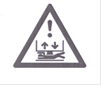
A notice clearly visible from the landing when the doors are opened shall be affixed on or near the mechanical device provided for unlocking the car door or on the fixed part of the apron, warning: “Apron shall be fully extended before rescuing persons.”
This notice may be accompanied by the warning sign given, as seen in Figure 3.
Height of Machine Room/Pulley Room

If the specified minimum height of 1,980 mm is not available in the working areas of the machine room/pulley room, soft material shall be fixed to the underneath of the beam/ceiling, and it shall be ensured that a height of minimum 1,800 mm is available up to the lower surface of the soft material. There shall be warnings in the form of yellow and black stripes, according to Figure 4, for example, fixed appropriately.

Height of Machine Room Doors
Access doors shall have a minimum width of 0.60 m and a minimum height of 1.70 m. They shall not open toward the inside of the room.
When the height is less than 1.80 m, suitable warnings, for example, using yellow and black stripes (Figure 4) and/or an adequate warning sign, shall be appropriately placed on both sides of the door.
Conclusion
With the aid of Indian Standard IS 17386, it is now possible to fit a new/upgraded lift in an existing structure with constraints, which would operate in a safe manner.
Disclaimer: The above article is written in good faith to educate and make people aware of the newly published Indian Standards on lifts IS 17386:2020. This article is meant to summarize and does not contain all of the information that may be relevant for any given condition. For that reason, users are advised to refer to the original text.
All figures are taken from IS 17386:2020 published by the Bureau of Indian Standards.
Further, the views expressed are personal to the authors. The authors/publisher or the organizations where the authors may be employed shall not be held responsible for any action taken by anybody based on the information contained in the article.
Pravin M. Tipnis, founder consultant, Tipnis Consultancy

Pravin Tipnis holds a degree in mechanical engineering from Veermata Jijabai Technological Institute, Mumbai, as well as a post-graduate degree from Indian Institute of Technology, Bombay, and has experience of more than 36 years in the VT industry. This includes 19 years at Olympus Elevators in technical/product development areas, which he headed, and, subsequently, 10 years at KONE, where he was responsible for various large infrastructure projects, such as metros, airports, etc. and high-rise buildings. An active post-retirement VT consultant offering his services to various small and big Indian and multinational companies, Tipnis specializes in technical training, code training and product/component consultancy. He has been an active member in code committees of Elevators, Escalators, and Moving Walks “ETD 25,” as well as the National Building Code of India “CED 46” for several decades. Currently, he is the convener of the Working Group Panel P4 of the ETD 25 committee. Relevant publications to his credit include “Occupant Evacuation Lifts: Fire India 2019 Conference” and “Elevator Car Ventilation Design to Mitigate the Risk of Spread of COVID 19: Research Square.”
Abhijit Dandekar – director Quality, Product Safety & Continuous Improvement – Asia Pacific; a member of ET25 (P4 panel) Elevator and Escalator Code Committee of Bureau of Indian Standards

Abhijit Dandekar is an electronics engineer with post-graduation experience in marketing management. Dandekar is working as director —Quality, Product Safety & CI at Otis’ Asia Pacific regional headquarters. With almost 34 years of experience at Otis, his expertise spans across various functions including Otis’ R&D department, field engineering, training, quality, product safety, Lean manufacturing, supply chain and codes. Responsible for product and process quality, thus increasing reliability and customer satisfaction along with product safety enhancements, are key objectives.
A member of ET25 (P4 panel) Elevator and Escalator Code Committee of the Bureau of Indian Standards, he has been liaising with Government authorities for consultation on “amendments to local elevator codes” for Maharashtra and Gujarat states. He is also a member of CED46 (P16 panel) responsible for drafting National Building code of India as well as a member of the ISO (International Organization for Standardization) technical committee TC 178 (and its four workgroups viz. WG4, 6, 11 and 12) representing the India delegation from BIS in the past six meetings held in Russia, U.S., South Africa, Australia, India and Germany.
Get more of Elevator World. Sign up for our free e-newsletter.


