An examination of possibly the first publication of a complete passenger elevator system
The January and February 2017 issues of ELEVATOR WORLD included a two-part article titled “An Innovative Elevator System,” which addressed an early Otis elevator depicted in what is believed to be the first U.S. publication of a set of drawings illustrating a passenger elevator from cellar to penthouse. As noted in the article’s introduction, “The caution that should be used in evaluating any claim of a first has been addressed in previous articles: there is always the possibility that an earlier example may be awaiting discovery.”[1] This suggested caution prompted the statement that these drawings, which appeared in 1870, were apparently the first such drawings published in the U.S. They were, in fact, preceded by a drawing of a British elevator system published in 1864. This earlier drawing claims pride of place as the leading contender as the first European publication of a complete passenger elevator system, as well as, perhaps, the first such drawing that appeared anywhere.
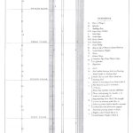
The drawing was one of a series produced to accompany a paper by architect John Whichcord, Jr. (1823-1885) presented at the January 18, 1864, general meeting of the Royal Institute of British Architects. It was also the sole illustration that accompanied the publication of Whichcord’s paper, titled “On Hydraulic Lifts,” which appeared in late 1864 in Papers Read at the Royal Institute of British Architects, Session 1863-1864. This remarkable drawing was reproduced as a large foldout: 10.5 in. wide and 24 in. long (Figure 1). Prior to an examination of the drawing, it is important to examine the context and content of Whichcord’s paper, as this explains why the drawing was produced and what it represents.
In the early 1860s, the appearance of passenger elevators in England followed a similar pattern to events in the U.S., with elevators first introduced to the public through their use in large hotels. This use was accompanied by a remarkably similar assessment of the need for this new technology. Whichcord claimed that, in regard to London:
“Everyone knows the enormous value which land has reached in this metropolis, and everyone who reflects on the wholesale destruction threatened in all parts of it must feel that, day by day, the space left near our great centers of business must become of much greater worth, and that we shall ultimately be compelled. . . to seek that room upwards.”[2]
The solution to this problem was, of course, the passenger elevator, which was “calculated to make a complete revolution in future building operations.” Like his American counterparts, Whichcord primarily saw the elevator as a domestic device and characterized its potential in terms of contemporary train travel:
“For instance, a whole family, with all their paraphernalia of luggage, enter a small room, which, on simply opening a valve, ascends by that gigantic yet most manageable of all powers, hydraulics, slowly and safely, and lands them on any floor, however elevated, on a level with their own apartments. What the locomotive has been to the traveler, the hydraulic lift will be to the dweller in elevated stories, and it is not unlikely that [it]. . . will hereafter be found in every moderate-sized private house.”
However, a critical difference between the American passenger elevator and the British passenger lift was the preferred use of hydraulic, rather than steam power.
Whichcord devoted a significant portion of the first half of his paper to a history of hydraulic power from the Ancient Greeks to the present day. The remainder of this lengthy introduction concerned the history of British freight elevators. These blended stories allowed Whichcord to come to the following conclusion regarding the superiority of hydraulic elevators:
“There are many reasons. . . why hydraulic power is more suitable for this class of lifts than any other; one of the strongest being that it is always available at any moment by the simple act of opening a cock or valve without any labor in getting up steam. . . . Beyond this, the entire absence of any danger arising from explosion through the neglect of ignorant or careless workmen, which forms so great an objection to the use of steam or gas (especially in establishments where skilled labor is wanting), the ease with which they are managed and the simplicity of the machines, render them capable of being worked by any person, so that in hotels or private houses, the owners are not at the mercy of the man who has charge of the apparatus, as is too frequently the case where machinery is employed.”
These statements also introduced the second half of the paper, in which he provided a “precise” and “illustrated description” of a hydraulic passenger elevator.
Whichcord was the architect of the Brighton Hotel, a six-story building completed in 1864. The building featured five hydraulic elevators designed and built by Easton, Amos & Sons of London: one passenger elevator that traveled the ground to the fifth floor (rise: 56 ft.), one elevator for luggage running from the basement to the fifth floor (rise: 77 ft., 7 in.), a wine elevator from the cellar to the ground-floor bar (rise: 16 ft.), a “food” elevator from the basement to the fifth floor (rise: 79 ft., 3 in.) and a second food elevator from the basement to the large coffee room on the ground floor (rise: 16 ft.). Water pressure was provided by a tank located in one of the hotel’s corner towers (a height of 124 ft. above the basement floor). The drawing that accompanied Whichcord’s published paper illustrated the passenger elevator.
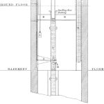
The drawing starts at the bottom with a partial view of a below-grade cylinder placed in a “borehole” that was “lined in the usual way with an iron casing, so as to prevent the earth falling in upon the cylinder” (Figure 2). Twin beams stabilized the top of the cylinder, which terminated in a “stuffing box” approximately 10 ft. above the basement floor. The control valve was located near the floor and operated by a combined “starting” or shipping rod and rope system. A movable vertical rod placed in “small cast-iron guides” ran along the shaft wall. It was connected at the bottom to the control valve by a horizontal lever; it was connected at the top to a shipper rope that passed through the car. The shipper rope employed a weight described as “sufficient to counterbalance that of the vertical rod.” When the elevator operator pulled the rope up or down, the vertical rod moved the horizontal lever in a corresponding direction, causing the car to descend or ascend.
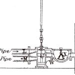
The control valve included a “regulator,” which was intended to ensure that the elevator did not exceed a preset speed of 60 fpm (Figure 3). The regulator employed a “brass quadrant,” a quarter-circle-shaped element suspended in the center of a cast-iron box. The quadrant, or “swinger,” was made such that it accurately fit the valve’s inlet and outlet passages. Its operation was as follows:
“When the velocity of the water, in either direction, does not exceed that decided upon, the swinger hangs in a vertical position without moving, but the instant the velocity increases beyond that point, i.e., the instant the lift moves at too great a speed, the swinger rises and closes the passage to such an extent as to reduce the speed to the normal velocity, without impeding in any way the [static] force of the water under any pressure whatever.”
A final feature depicted in the drawing’s lower portion is the counterweight, which was composed of “square cast-iron weights strung on a wrought-iron rod” supported by an iron chain that passed over a large sheave at the top of the shaft and was connected to a “wrought-iron ring” on top of the car. The counterweight was intended to balance the car, while the chain was intended to counterbalance the plunger or ram: as the plunger rose upward, the extra weight added to the counterweight was described as “exactly equivalent to the increase in the weight of the ram by its removal from the water.”
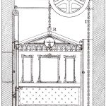
Above the basement level, the drawing depicts the cast-iron plunger and guide rails, which were described as “cast-iron A-shaped guide bars, accurately planed and bolted firmly to the walls in a perfectly straight and perpendicular line.” Sitting atop the plunger was the car, or “ascending room” (Figure 4). The car featured a “strong cast-iron bottom” on top of which was a “wrought-iron framework filled in with wood and glass.” The car traveled along the guide rails via four V-shaped brass shoes, the tops of which were “made in the form of a cup, in which a sponge kept saturated with oil will be placed so as to lubricate the guides and guide bars every time the room passes up and down.” The car also featured an upholstered seat, gas chandelier and sliding door.
The elevator’s control system was designed to automatically stop the car at a specific floor. In addition to the shipper rope, the car featured an interior control lever that allowed the operator to select a specific destination (Figure 5). The lever controlled a “lug” that projected into the shaft. The vertical shipper rod featured “pins” — one per floor — of different sizes that Whichcord characterized as analogous to the pins in a music box in that they were “not directly over each other, but are one in front of the other,” projecting “in front of the rod to such an extent as to allow the side of the ascending room [to] just [clear] their points.” The system worked as follows: the operator would slide the lever to the destination floor; this action would position the lug such that it would catch the appropriate pin. Then, he would pull the shipper rope to start the car’s movement. As the car approached its destination, the lug would engage the pin, which would raise (or lower) the vertical rod, thus returning the control-valve lever to its horizontal or stop position. Whichcord claimed this system ensured the elevator would stop “the instant the water is shut off by the lever” and that the car would be “exactly level with the floor or landing.”
Unfortunately, the only drawing associated with Whichcord’s 1864 presentation to survive is the one illustrating the passenger elevator. This is particularly unfortunate, as the luggage and low-rise food elevators operated “on a different principle,” described as “a horizontal cylinder and piston, giving motion to rack-and-pinion gearing, which causes a hauling drum to revolve and thus winds up the chain to which the cage or lift is attached.” The luggage elevator utilized the “same species of starting valve and gear” found on the passenger elevator; thus, the hotel “porter who shows the passengers to the lift can put the luggage into the cage and set the handle to the proper mark on the index plate, and the cage will stop at the floor until unloaded and sent down again by pulling the rope.”
Regrettably, no accounts of these elevators that could corroborate (or disprove) Whichcord’s claims regarding their imagined operation have survived. There is also a question of the drawing’s influence. Although numerous other publications reprinted excerpts from Whichcord’s text, the drawing was, apparently, never republished. Thus, only members of the Royal Institute of British Architects or people with access to technical libraries would have seen the drawing. Nonetheless, it remains a remarkable and, very likely, genuine first in the history of vertical transportation.
- Figure 1: “Hydraulic Passenger Elevator” designed by Easton, Amos & Sons, London (1864)
- Figure 2: “Hydraulic Passenger Elevator,” detail: a = control lever, L = supply water, M = waste pipe, H = cylinder, K = cast-iron girders, and l = weight.
- Figure 3: “Hydraulic Passenger Elevator,” “Regulator”: H = cylinder, L = supply water, M = waste pipe, U = starting valve, W = junction pipe, and X = regulator.
- Figure 4: “Hydraulic Passenger Elevator,” detail: P = sheave, T = counterbalance chain, and O = cast-iron A-shaped guide bars.
References
[1] Dr. Lee Gray. “An Innovative Elevator System, Part One,” ELEVATOR WORLD, January 2017.
[2] John Whichcord, Jr. “On Hydraulic Lifts,” Papers Read at the Royal Institute of British Architects, Session 1863-1864, 1864. Note: All following quotes derive from this source.
Get more of Elevator World. Sign up for our free e-newsletter.
