Optical Fiber in Elevator Traveling Cable
Aug 1, 2013

This article outlines the types and uses of fiber optics for elevators and explains financial and technical benefits, as well as the perceived and actual installation challenges. The need for communications in elevators has evolved beyond the need to tell the machine room to which floor to travel. High-definition security video, phones, control signals and audio (both two way and “elevator music”) are all carried by some sort of dedicated communication circuit in the traveling cable.
Classically, there have been three types of cables used for signal transmission, including:
- Coaxial, used primarily for video in RG6 and RG11 constructions
- Shielded pair, used primarily for telephony and consisting of usually 20 American wire gauge (AWG) copper with a braided copper shield
- Optical fiber, which can carry any number of digitized voice, video, audio and data signals over great distances
Coaxial and shielded-pair cables have been around for decades and are known quantities for elevator craftspeople. They terminate easily to analog cameras, phones and speakers. However, newer devices used in elevators are being asked to carry more and more signals at higher data rates (increased bandwidth). They are also operating digitally. While coaxial and shielded-pair cables can carry digital signals, they do not do it efficiently. Optical fiber features significant bandwidth and is suited to carry fast digital traffic.
Optical fiber has a reputation for being difficult to install and expensive to operate. However, breakthroughs in low-cost electronics (and the general advance of digital devices), as well as refinements in installation hardware, now make optical fiber an attractive choice for elevator communications.
Ethernet, UTP and Traveling Cable
Ethernet is the standard for data cabling. Almost every modern device uses Ethernet protocols to communicate. Ethernet commonly operates at speeds of 10 or 100 Mb/s (Base-T) over unshielded twisted-pair cable (UTP), usually known by its category rating such as Cat 5e or Cat 6.
UTP is used for data transmission of up to 100 m from device to device. UTP does this by the twisting of paired solid 24-AWG copper wires. The precision of this twisting is essential to performance, as it is the mechanism that minimizes crosstalk between the four pairs of wires that make up the cable. Any untwisting of the pairs will degrade the signal. When UTP is installed in an office network, effort should be made to keep it from dangling, swaying or flexing like a traveling cable.
One may question whether UTP can be used in traveling cable. It is doubtful, as the constant flexing of traveling cable could cause the pairs to untwist. At this time, the National Electrical Code standards defined in Articles 620.11 and 620.12 do not permit copper wire smaller than 20 AWG in a traveling cable. However, cabled optical fiber is fine for traveling-cable use and offers a range of benefits.
How Optical Fiber Works
Optical fiber is a thin strand of glass that guides light along its length. A light source, such as an LED or laser, injects pulses of light into one end of the fiber. The fiber has a core that transmits the light and a cladding that has a different refractive index than the core that “contains” the light. Acrylate coatings build the strength of the cable, and a plastic coating called a tight buffer overlies the fiber. The buffer increases fiber diameter and makes it easier to handle, while adding mechanical protection. Optical fiber may be cabled for further strength, though this is not normally needed in elevator applications. To further protect it during the constant flexing of a traveling cable, the tight buffered fiber is covered with high-strength aramid yarn and an overall flame-retardant jacket.
A typical fiber-optic circuit has an electronic device, such as a camera, at the transmission end. The signals from the device are carried over a connecting cable (usually coaxial or UTP) and converted to optical digital signals by means of an electro-optical converter. At the receiving end, the light is changed back into an electronic signal connected to a device such as a monitor or fed into a data system.
An advantage of optical fiber is that it can carry high-bandwidth signals (such as high-definition, closed-circuit TV) over much greater distances than any copper cable can. Depending on the selected electronics, input from multiple cameras, high-definition audio, emergency phones and even cab telemetry can be sent over a single or pair of fiber(s). In addition, optical fiber is immune to electrical interference.
Single Mode Versus Multimode
The path the light takes through the fiber is called a “mode.” A single-mode fiber has a tight core, typically 6 µm (a bit larger than the diameter of a red blood cell), that allows light to propagate on just one path. Multimode fiber has a larger core — traditionally 62.5 µm, but newer types of fiber have a 50-micron core. The larger core has as many as 300 possible paths for light to propagate. Multiple modes are not quite as efficient as a single mode but are easier to work with.
Single-mode fiber is the higher performing of the two technologies. It is generally used in telecommunications for long-distance transmission, as it can carry a significant amount of bandwidth over distances of 70 km before needing to be repeated. Powerful lasers are used as the light source of a single-mode cable at 1,310-1,550-nm wavelengths.
Operating over shorter distances (typically, multimode fiber is used for shorter runs of a 1/4 or 1/3 mi.), multimode fibers use LEDs and vertical-cavity, surface-emitting lasers as light sources at the 850-nm wavelength. Until a few years ago, the cost of these electronics made using them in elevators hard to justify. However, the price of these and their related devices have become more reasonable, making high-bandwidth transmission economically feasible for elevators.
Multimode is among the recommended fiber types for elevators. Along with the lower cost of the electronics, multimode fiber is easier to work with and connectorization is more forgiving. This does not exclude using single-mode cable. The cable installed in Dubai’s Burj Khalifa has 14 multimode and six single-mode fibers in each of its many cables, though the single-mode fibers were not activated and placed for future use.
The operating range of multimode fibers can be measured in hundreds of meters, far exceeding UTP or any other copper cable type. As a general rule, Draka Elevator Products offers 62.5-µm multimode fiber in its traveling cable, although 50-µm fiber is available as an option. It should be noted that 50-µm fiber offers higher performance, with data rates of as much as 100 GB per second (called “laser-optimized” OM3 or OM4 fibers), but 62.5-µm fiber should be sufficient for elevator applications.
Connectorization: Perceptions and Realities
Along with the expense, perception of the difficulty of connectorizing fiber has been a barrier to its implementation. However, refinements in technology and technique have made this process easier. There are several versions of fiber connectors, some designed for specific applications. They consist of a ferrule, which places the fiber end squarely and securely at the connection point, some manner of locking mechanism and a body to protect the fiber and ease of handling. Most designs put the fiber end in direct contact with the input or output of the optical electronics.
The most commonly used connectors are straight tip (ST) and square connectors (SC). The ST type is a cylindrical bayonet connector that twists into place and is held by spring pressure. A drawback is that if the cable is tugged, there is the possibility of interrupted data flow. The SC locks in place and offers non-optical disconnect; unless the locking lever on the connector is manually released, the connection cannot be interrupted. Both types offer about the same level of optical performance.
Connectors generally come with the desired fiber installed within and the connector end polished for minimum loss of signal. Several feet of fiber extend from the connector. This tail is generally welded or “fusion-spliced” to the fiber in the traveling cable. A clean and low-loss fusion splice can be performed with the right equipment and practice.
An outline of the process includes the following steps:
- Strip the buffering from a small section of the traveling cable’s optical fiber to expose the fiber.
- Cleave the fiber end to produce a clean and perpendicular cut.
- Place a fiber sleeve over the cleaved fiber.
- Use a fusion splicer to attach the fiber end of the connector to the fiber end of the traveling cable.
- Reinforce the splice with a protective sleeve.
- Test the connection for loss with a light source and power meter.
For a detailed video of the splicing process visit, website: www.youtube.com/watch?v=L8iXJiBtvuI.
Fusion splicers are available for rent or purchase. Tool kits, complete termination kits and training classes are available for fusion splicing. It is important to note that lasers and LEDs produce powerful infrared light. In the same way that one should not touch a live electrical wire, one should never look directly into an optical fiber, as it could cause severe eye damage.
Conclusion
Optical fiber is a beneficial way to carry high-bandwidth signals, especially video, to and from the elevator. The necessary electronics are both affordable and reliable. The preferred fiber is 62.5-µm multimode, although 50 µm is an acceptable alternative for high-speed applications, using SC or ST connectors. The connection process is straightforward and can be quickly mastered.

Typical application of a fiber-optic circuit 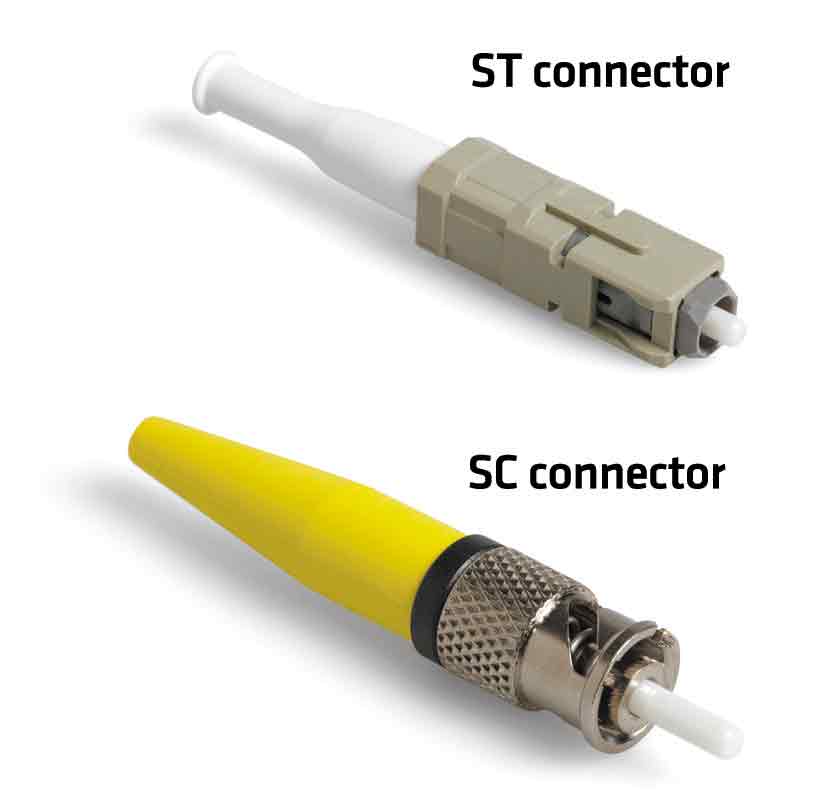
The most commonly used types of connectors
Get more of Elevator World. Sign up for our free e-newsletter.