Oscilloscopes, Part One
May 1, 2016

An introduction to the complex educational tool that has varied uses.
In this first of a two-part series, we will consider the oscilloscope as an educational tool. It is a wonderful gateway into the world of electronics, and it seems there is no end to the multiple layers of elementary particle interaction it can reveal.
When one takes a new oscilloscope out of the box, the first reaction may be, “What was I thinking? How did I ever get myself into this? So many knobs and buttons, and endless cryptic menus!” But don’t worry. The operating manual, print or online, clarifies a great deal, and remaining information gaps disappear one by one as first elementary and then successively more complex exercises are performed.
Learning Objectives
After reading this article, you should have learned about:
♦ The history of the oscilloscope
♦ The principal components of an oscilloscope display
♦ The purpose of the X and Y axes
♦ Important innovations in oscilloscope development
♦ Disadvantages of TV conversion and the computer-based oscilloscope
The modern digital oscilloscope consists of probes; analog channels (usually two or four); analog-to-digital conversion; processing and memory; and, finally, a display (now predominantly on a flat screen). Typically, there are two axes, X and Y, that intersect at the center of the screen. A spot of light moves vertically and horizontally across the screen to form the trace, which is a graphic representation of the voltage applied at the input of the instrument.
In its most common application, the oscilloscope is configured so that the location relative to the Y axis represents voltage, and the location relative to the X axis represents time. Crossing the axes at right angles to them are lines (known as “divisions”) that make it possible to gauge the voltage level of the signal at specific time intervals. The trace so constituted may be moving or static, but, either way, it conveys an immense amount of information about the signal being investigated.
History
To understand how the oscilloscope works, it is instructive to take a look at its history, particularly in regard to two milestones: triggering and the digital storage scope. The first oscilloscopes involved capturing waveforms by means of measuring voltages at various points along the circumference of a spinning rotor. A permanent record in the form of a graphical image was made by hand drawing the image on paper. Needless to say, frequency response was limited by the speed and endurance of the artist(s).
Subsequent oscilloscope innovations were incremental. The first major breakthrough involved use of a galvanometer, which moved a pen across a strip of paper wrapped about a drum. It rotated at a constant clock-driven rate, which provided the time base. Similar subsequent methods also involved moving parts, and because these machines were mechanical (as opposed to electronic), inertia of rest placed a severe limit on frequency response.
Breakthroughs
Hybrid equipment, where reflected light from a trembling mirror created waveform images on photographic paper, ramped oscilloscope frequency response as high as 10 kHz by the 1920s. Later in that century, two substantial innovations occurred that made possible the oscilloscopes used universally today.
The first of these was triggering, introduced by Howard Vollum and Jack Murdock, founders of Tektronix. In 1946, they brought out the Tektronix Model 511 triggered-sweep oscilloscope, which facilitated a stable and coherent display of a recurrent waveform. This expedient permitted multiple waveform images to coincide on the oscilloscope screen, replacing the meaningless blur of light resulting from lack of synchronization. An unchanging frequency sweep input was not required for image stability.
The other significant development occurred prior to the 1980s, when Walter LeCroy, founder of LeCroy Corp., introduced the digital storage oscilloscope. An analog-to-digital converter in conjunction with memory chips permit contemporary oscilloscopes to record and store a digital representation of any sort of electrical waveform. This development facilitated the flat-screen display. Together with effective triggering, digitization has created a work platform that is immensely useful to engineers, technicians and students to visualize diverse electronic phenomena and solve many problems that arise in research, development and maintenance.
Types
“Electronic technician” is a broad term and can include the electrical engineer who conceives of, designs and may be called upon to debug new innovations. Then, there is the “repair professional,” whose job description includes diagnosing and repairing dysfunctional electrical systems and equipment. This task may range from very simple (like resetting a tripped breaker or replacing a worn power cord) to very difficult (like troubleshooting an elevator motion controller that cuts out at odd intervals for no apparent reason). Another category is the serious independent inventor or home hobbyist. These folks range from brilliant innovators who are occasionally at the cutting edge of some altogether new technologies to delusional cranks who break more than they fix.
Any of these individuals can benefit greatly by having the use of an advanced oscilloscope. The sad reality, however, is that a top-of-the-line instrument costs far more than many of us can afford. (The most expensive Agilent is priced at approximately US$500,000.) But, the good news is that midrange oscilloscopes are much less costly. Many vendors offer financing designed to attract buyers. It is not difficult to imagine that one’s enhanced earning power will accompany and justify the expenditure. If not, there are other low-cost options, and we will consider them one at a time, beginning with the cheapest.
TV
An old black-and-white portable TV can be converted into a viable oscilloscope. The price of materials is about US$1, assuming a suitable TV can be had at no cost and the solder and flux, wire, grommets and voltmeter probes are already available.
Before starting, remember that TVs harbor hazardous high voltages retained in the electrolytic capacitors associated with their power supplies. (High voltage levels are needed for the deflection circuitry capable of moving the beam of electrons away from the center of the screen.) Moreover, the cathode-ray tube (CRT) itself can store electrical energy. Then, there is also such a thing as distributed capacitance throughout the set. The chassis must be removed from the cabinet and these hazardous voltages discharged to ground potential before starting to work on the set. If you are at all uncertain of the procedure, call a professional to help with this phase of the project. And, remember that if the set is reenergized, the discharging process will have to be repeated.
Two large copper coils surround the cathode-ray tube yoke. They make possible vertical and horizontal deflection of the electron beam. (In an oscilloscope, they are deflection plates, but the principle is the same.) Trace the wires of one of these coils back to where they terminate at a circuit board and disconnect them. Return the TV to its case and power it up. If there is a horizontal line, the wires from the vertical deflection coil have been disconnected, and if there is a vertical line, the wires from the horizontal coil have been disconnected. If necessary, desolder the vertical coil from the circuit board and make the leads long enough to pass through a grommeted hole in the TV cabinet. These wires will attach to the outside power source to be measured. Then, disconnect the horizontal coil wires from the circuit board and move them to the vertical deflection-coil terminations.
Nothing further is required for a homemade oscilloscope. Unfortunately, it is very limited compared to instruments offered by vendors. As it can display only DC or a low-frequency AC waveform its value is limited to an educational project.
PC Based
Another type of oscilloscope is an instrument that connects to a personal computer (PC), making use of its data processing and imaging ability to display voltage from an outside power source or circuit under test. The PC-based oscilloscope (PCO) consists of a specialized signal-acquisition board. It takes different forms, typically an external USB or parallel-port device. Another type of PCO consists of a card installed in the computer. For hardware, there is an electrical interface providing isolation and automatic gain controls, some analog-to-digital converters and buffer memory, or an internal digital signal processor. Display and control interfaces are provided by the computer, and it is for that reason that the cost of a PCO is much less than that of a full-scale oscilloscope.
As may be expected, there are some significant disadvantages in going the PCO route, despite the surprising functionality of some of the better instruments. The principal drawback is that the computer is a source of power supply and electromagnetic noise. If the PCO is endeavoring to examine low-level signals, obtaining good resolution may be problematic, requiring extensive shielding. A further difficulty is that transfer rates into the computer are certain to be limited by the weakest link in the chain, a bottleneck inherent in the cabling media. Additionally, the computer will require oscilloscope-enabling software, which may or may not be compatible with the operating system. Of course, compatible computers usually do not have the great life expectancy of high-quality dedicated oscilloscopes. Overall, the PCO is valuable as an educational tool for hobbyists and students. It is useful for some low-frequency measurements, but speed and precision are lacking. For serious research and facility maintenance, the PCO is an idea that has not yet (and probably never will) come.
Used
Another low-cost option is to buy a used oscilloscope. The problem here is that, even if the oscilloscope appears to work, it may be observed later that some of the features are not fully functional. If you can find parts and have the expertise to repair it, that is fine, but when factory recalibration is needed, it may not be available. This option is not recommended.
New
Finally, if cost is not an obstacle, consider buying new. There are numerous manufacturers, some catering to the low-end market, while others have been and are currently investing in R&D, seeking to provide top-level quality and functionality. The big players are Tektronix, LeCroy and Agilent (recently spun off into Keysight Technologies but keeping essentially the same product line). These vendors offer high quality, very advanced and durable oscilloscopes that should be valuable for years to come.
Features and Functionality
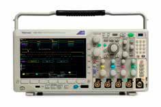
A mixed-domain oscilloscope (MDO) is capable of displaying electrical signals in more than one domain. The domain associated with a function, as calculus students are well aware, is the set of inputs allowed for that function. The oscilloscope display consists of a horizontal line, the X axis, along which the inputs are situated. At the center of the display, the Y axis, along which the outputs are situated, intersects the X axis.
The most common scenario is to see units of time referenced to the X axis, where the independent variables are represented. Amplitude (voltage) is referenced to the Y axis. Various amplitudes comprise the dependent variables. The relations between points on the X axis and points on the Y axis are determined by the function.
Sometimes, the domain (X axis) does not represent time. Instead, it can be defined in terms of frequency (with Y values still being amplitude). This makes a different graphic depiction of the same electrical signal. It is possible to translate back and forth between the two domains, and the procedure for accomplishing this is known as the Fourier Transform, described in 1822 by Joseph Fourier. The protocol at the time was applicable to nonelectrical phenomena, such as wave action in a body of water and acoustical mechanics. In our time, the main focus is electrical.
The mathematics for accomplishing the Fourier Transform are immensely complex, but in the mid 1960s, an algorithm known as the Fast Fourier Transform (FFT) that greatly accelerates the process surfaced. This procedure permits us to accomplish the same back-and-forth translations between the two domains with less burdensome calculations. Fortunately, FFT can be invoked in an instant by pressing a simple sequence of buttons on an MDO, and an electrical signal can be seen immediately in either of the domains. This functionality is very useful in gaining insight into the inner workings of many types of electronic equipment for purposes of maintenance, as well as R&D.
Grounding
Before powering up or connecting a bench-type oscilloscope to a signal, we need to go into some detail on the concept of grounding both the instrument and the circuit under investigation. If this is not thoroughly understood, there is the strong probability that the user will eventually make an improper hookup and damage or destroy the oscilloscope and/or the work being measured.
First and most fundamentally, the oscilloscope (unless it is the handheld, battery-operated type that is isolated from ground) must be correctly grounded whenever it is powered up. This ground connection is accomplished by plugging it into a standard three-prong receptacle that has an equipment ground. This presupposes, of course, that the equipment-grounding conductor is intact and properly connected at the electrical service and that the overall system has a low-impedance connection to the earth. A good tool for verifying that the wiring is polarized correctly (and, indeed, grounded) is the circuit analyzer (Figure 2).
The purpose of the equipment-grounding connection is to ensure that the oscilloscope chassis, like that of any tool or appliance, does not remain energized due to a ground fault, resulting in a shock hazard. Secondly, the electrical equipment being tested must be either totally isolated from ground, or, if powered by utility-derived AC power, it (like the oscilloscope) must be powered by two conductors, one of which is at ground potential. If one of these is not the case, it is not safe to connect the oscilloscope to the work.
Moreover, the ground reference lead that is part of the probe must be connected to a point in the circuit under test that is at ground potential, leaving the probe tip available to contact points within the circuitry. It is essential that the signal ground of the circuit under test and the oscilloscope equipment ground derived from the AC utility are at very close to the same potential. If these conditions are not met (i.e., equivalence of both grounds and correct hookup of the oscilloscope probe ground reference lead), there will be a heavy fault current that will, at the very least, burn up the probe ground reference lead and, perhaps, damage the oscilloscope and/or the equipment under test. This will happen instantly when the ground reference lead contacts a point in the circuitry that is not at ground potential. In fact, it will occur even before the probe tip contacts the equipment.
There are some exceptions to the above grounding protocol. The oscilloscope may be isolated from ground by sawing off the ground plug from the power cord. While this expedient may work to prevent the problems mentioned above, it is contrary to the National Electrical Code and constitutes a depraved indifference to human life, because it disables the protective functions of equipment grounding. It sets the stage for disaster down the road.
As mentioned earlier, the hazard under discussion is not an issue when the work is totally isolated from ground. An obvious example would be the waveform (a straight horizontal line) of a 9-V battery. Since neither side is at ground potential, it is safe to connect the probe’s ground reference lead to either the positive or negative pole.
A portable handheld, battery-powered oscilloscope (Figure 3) may be connected to point-to-point wiring within grounded electrical equipment. Since both sides of the instrument are isolated from ground, there will not be a hazardous ground fault, regardless of which way the probes are connected.
With a bench-type grounded oscilloscope and the need to make a point-to-point measurement on grounded equipment (such as measuring the DC bus voltage of a variable-frequency drive), it is permissible to use a differential probe (Figure 4). Differential probes combine the functions of two probes in one. Singled-ended probes measure a voltage with reference to a ground point. In contrast, differential probes measure the difference in voltage between two test points. There is not the issue of hazardous arc flash caused by connecting the probe ground lead to a signal voltage that is floating with respect to the ground plane. Important characteristics to look for are high bandwidth, large dynamic and offset range, and low noise.
Conclusion
This article has examined some background information on oscilloscopes, particularly as they have developed during the past century. In the next and concluding article in this series, some exercises that illustrate the use of an oscilloscope, with reference to the Tektronix MDO3104, will be performed. A few simple hookups will demonstrate how the oscilloscope can be used to depict waveforms and illustrate various electronic phenomena that are invisible to the multimeter.
Learning-Reinforcement Questions
Use the below learning-reinforcement questions to study for the Continuing Education Assessment Exam available online at www.elevatorbooks.com or on p. 139 of this issue.
♦ What is the principal hazard in removing a TV from its cabinet?
♦ What was the great contribution of Tektronix in the oscilloscope’s development?
♦ What was the great contribution of LeCroy in the oscilloscope’s development?
♦ What is a PCO, and what are some of its drawbacks?
♦ What is an MDO?
Get more of Elevator World. Sign up for our free e-newsletter.


