Engineering study considers attributes of SGP with directly mounted handrails.
by Dr. Iraklis Chatziparasidis and Dr. Dimitrios Giagopoulos
This article was first presented at the 2018 International Elevator & Escalator Symposium in Istanbul. For more information on December 3-4, 2019’s event in Las Vegas and to participate, visit www.elevatorsymposium.org.
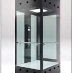
The car is one of the most significant elevator components, because it is used to carry goods and people and, thus, is subject to strict legislations and standards that differ in each country or other AHJ. At the same time, the car is usually the only functional component of the elevator visible to the final user. This fact makes the car an architectural and decorative element of the building. The latest trends in architecture are to use fully transparent glass building elements.[1] A frameless glass panoramic elevator (Figure 1) not only fits this trend, but also extends the aesthetic of the building. However, glass is a brittle material prone to fatigue failure, and this characteristic made the verification of the material-load-carrying capacity to be mostly based on experimental studies.[2] Some research has been done in the field of modeling of the behavior of glass components using finite element (FE) methodologies, but these are mainly studying static load situations aimed at the building construction domain.[1, 3 & 4] In this work, we first present a method for modeling glass components in dynamic situations that may occur during an elevator’s function — e.g., when the safety gear of the elevator is activated during an emergency stop or the car hits the pit buffer. Second, we apply the above method in a full-glass, frameless panoramic car analysis using laminated glass with a stiff SentryGlas® Plus (SGP) having the handrails mounted directly on the glass elements. Finally, we discuss the safety issues by comparing the current EN 81-xx standards requirements with the numerical and experimental results of the above analysis.
EN Standards Requirements
In this section, we present the requirements that the current European Norms (EN) impose for the elevator car handrail function:
“EN 81-20
“5.4.3.2.4 The fixing of the glass in the wall shall ensure that the glass cannot slip out of the fixings during all shock conditions encountered in both directions of travel, inclusive of operation of safety devices.
“5.4.3.3 Car walls with glass placed lower than 1.10 m from the floor shall have a handrail at a height between 0.90 m and 1.10 m. This handrail shall be fastened independently from the glass.
“EN 81-70
“5.3.2.1 At least on one side wall of the car a handrail shall be installed. The gripping part of this handrail shall have cross- sectional dimensions between 30 mm and 45 mm, with a minimum radius of 10 mm. The free space between the wall and the gripping part shall be a minimum 35 mm. The height of the top edge of the gripping part shall be within (900 ±25) mm from the car floor. The handrail shall be interrupted where the car operating panel is located on the same wall in order to avoid obstructing buttons or controls. The projecting ends of handrails shall be closed and turned towards the wall to minimize the risk of injury.
“EN 81-71
“5.4.1.7 For Category 2 lifts, any handrail shall be capable of supporting at its most unfavorable point a force of 2,500 N applied in any direction.”
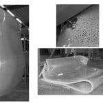
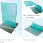
According EN 81-20, the handrail shall be fastened independently from the glass. Also, according to “Guidance for European Structural Design of Glass Components,”[5] when a laminated glass panel utilizing a polyvinyl butyral (PVB) interlayer is broken, it folds and falls downward. In Figure 2, the failure mode of common laminated glass panels utilizing a PVB interlayer is presented. This means that in a similar situation within a panoramic car, passengers will be exposed to the danger of falling out of the car, and the only barrier between them and the gap would be the handrail. A situation like this justifies the above EN 81-20 requirement. However, it is clear that the EN standards relative to the most common type of elevators — EN 81-20 and EN 81-70 — do not impose any specific mechanical strength requirements for the passenger handrails. In contrast to PVB, SentryGlas interlayers are five times stronger and up to 100 times stiffer than conventional laminating materials. SentryGlas interlayers create stronger laminated glass that protects against storms, impacts and powerful blasts. Figure 3 presents the post-breakage behavior of three types of glass panels.
The FE Simulated Dynamic Experiment Validation Method (SEVaM)
To accurately simulate the behavior of laminated glass components in a dynamic situation within a car elevator, it is important to develop an accurate FE analysis procedure. The work presented here is based on previous work where we demonstrated the advantages of applying appropriate numerical and experimental methodologies to accurately predict the dynamic response and identification of the critical points in an elevator system.[6-11]
SEVaM, which was developed during previous research work,[7] is applied here into a frameless panoramic car deploying laminated glass panels using a stiff SGP interlayer. The goal is to accurately simulate the dynamic behavior of the whole elevator system and, specifically, the handrail suspension directly on the car’s glazing. To achieve this, it’s necessary to verify the accuracy of the FE models used for simulations, which involve the application of a combination of numerical and experimental methods. SEVaM uses partially FE-simulated experiments to model much larger product configurations.
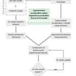
In SEVaM, the main experimental assembly is first divided into its major functional subsystems. An initial FE model based on the corresponding 3D computer-aided design (CAD) model is constructed for each subsystem. Then, the corresponding experimental structure for each subsystem is built. The procedure presented in Figure 4 is applied to validate the accuracy of the initial experimental product. For each subsystem, acceleration values are measured experimentally and passed as excitation forces to the FE model, and a dynamic analysis is performed.
From the FE results, high-stress areas are identified. In the experimental structure, strain cages are placed at the high-stress areas (identified by FE analysis), and stresses are measured experimentally. If the calculated and experimental stress values are not in agreement, FE model updating methods are applied; otherwise, the FE model is considered to be validated. When the subsystems’ FE models are validated, the experimental structures are synthesized to form the complete assembly, and a complete FE model is constructed. Experimental measurements are also recorded and compared to the calculated (FE) values.
FE Model Verification of a Glass Panel
The first step is to develop a high-fidelity FE model of the glass panel. To achieve this, it is necessary to optimize the numerical FE model of a glass panel, including the suspension component. Basic structural model updating methods have been proposed to reconcile the numerical (FE) model with experimental data.[12] Structural model parameter estimations based on measured modal data[13-19] are often formulated as weighted least-squares- estimation problems in metrics, measuring the residuals between measured and model- predicted modal characteristics.
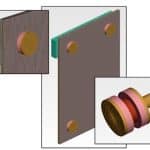
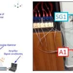
The geometry of the glass panel with the suspension component is discretized mainly by solid tetrahedral elements. Some appropriate software is used for the development and solution of the FE model.[20 & 21] The detailed FE model of the experimental device is presented in Figure 5. Two typical eigenmodes, predicted by the nominal FE model, are presented in Figure 6. After the development of the nominal FE model, an experimental modal analysis of the experimental setup was performed to quantify its dynamic characteristics. The system was tested in a fixed-free boundary condition. First, all the necessary elements of the frequency response function (FRF) matrix required for determining the response of the frame substructure were determined by imposing impulsive loading.[12, 19 & 22-24] The measured frequency range was 0-2,048 Hz, which includes the analytical frequency range of interest, 0-400 Hz. An initial investigation indicated the frame has six natural frequencies within this range. A schematic illustration of the experimental setup is presented in Figure 7. In this image, the locations of two triaxial accelerometers (A1, A2) and two strain gauges (SG1, SG2) are presented.
Figure 8 shows the magnitude of two typical elements of the FRF matrix before (continuous line) and after (dashed line) application of the Welsh’s smoothing method, which were recorded by the above experimental setup.
Based on the measured FR functions, the natural frequencies and damping ratios of the frame substructure were estimated. As an outcome of the above procedure, the first column of Table 1 presents the values of the lowest six natural frequencies ( ![]() rE) of the system examined, while the corresponding damping ratios are included in the fourth column. In the same table, the second column presents the values of the natural frequencies obtained from the analysis of the nominal FE model (
rE) of the system examined, while the corresponding damping ratios are included in the fourth column. In the same table, the second column presents the values of the natural frequencies obtained from the analysis of the nominal FE model (![]() rNFE), and the third column compares these frequencies with the corresponding
rNFE), and the third column compares these frequencies with the corresponding
frequencies obtained by the experimental data. The errors determined between the nominal FE model and the experimental measurements are insignificant, indicating the FE model updating process is necessary.
FE Model Parameterization and Updating Results
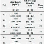
The parameterization of the FE model of the experimental setup is introduced to demonstrate the applicability of the proposed FE model updating method. The parameterized model consists of six parts (Figure 9). At each of these parts, the Young’s modulus and density are used as design variables. Thus, the final number of the design parameters is 12 variables. Table 2 presents the initial values that have been set in each parameter, which are identical to the nominal FE model’s upper and lower limits, which were selected to be used for the optimization process. The last column of the table shows the step of design, which is set at 1% of the respective previous value for all cases. The FE model is updated using the lowest six identified modal frequencies and mode shapes shown in Table 1. The identified mode shapes include components at all four sensor locations.
The results from the FE model updating method are shown in Table 3. This table presented a comparison between identified ( ![]() rE) and optimal FE-predicted modal frequencies (
rE) and optimal FE-predicted modal frequencies ( ![]() rOFE).
rOFE).
Complete Elevator System FE Analysis
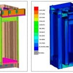
An FE model of a full elevator system using a frameless full-glass car is built after the validation of the FE model of the previous experimental setup. The complete model is solved numerically in transient response analysis to calculate the maximum stresses developed (Figure 10).
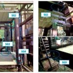
A full-glass frameless panoramic elevator (Figure 10) is designed and developed based on the results of the entire above procedure. It achieves minimum design stresses at the glazing components during dynamic load conditions caused by, e.g., emergency safety gear engagement. The design is also verified by a new experimental setup of the complete system (Figure 11), where SG labels index the positions where the strain gauges’ sensors were placed.
Frameless Full-Glass Car With Handrails on Glazing — FE Analysis
After verifying the elevator’s FE model, we proceed by modeling the handrail suspension on the glass components. Figure 13 presents a view of the complete FE model with the simulated concentrated force on the handrail. The force was selected to be applied close to the free edge of the large glass that constitutes the worst-case scenario for the emerging stresses.
Two different cases are examined. In case 1, a force of 3,000 N is applied in the horizontal direction, while, in case 2, a force of 2,000 N is applied in the vertical direction.
Numerical Results
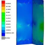
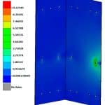
The FE model is solved numerically to calculate the maximum stresses developed in the glass surface for the given loading. In case 1, a maximum stress of 26.9 MPa is calculated (Figure 14). This value is much lower than the characteristic bending strength of either thermally toughened glass (120 MPa) or heat- strengthened glass (70 MPa.)[5] In case 2, a maximum stress of 9.3 MPa is calculated (Figure 15). This value is much lower than the nominal tensile stresses of 35-55 MPa[1] for 6-mm plate thickness.
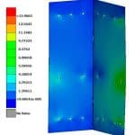
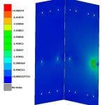
Next, the FE model is solved numerically to calculate the maximum stresses developed in an isolated SGP interlayer surface for the given loadings. In case 1, a maximum stress of 14 MPa is calculated (Figure 16), and, for case 2, a maximum stress of 4.9 MPa is calculated (Figure 17). Both these values are lower than the SGP tensile strength presented by Callewaert, Delincé, Sonck, Belis and Van Impe.[25]
Conclusions
We are questioning the EN 81-20 requirement for having the handrail fastened independently from the glass when, at the same time, the main EN 81-xx standards do not have specific requirements for handrail strength. We discuss the safety issues that could arise in a scenario with a glass panel having a PVB interlayer that is completely collapsed, and we investigate if the usage of glass panels with an SGP interlayer (and the handrails directly mounted on them) can provide the same or an even higher safety level in contrast to the EN 81-20 requirements. To experimentally test this concept, we have used the proposed SEVaM. This methodology has been successfully used in simulated experiments in a case study for a full-glass frameless panoramic elevator car. Experimental measurements are used to validate the FE model, and this model is used for the calculations of the stresses caused by the handrail on the surface of the glass panels and SGP interlayer. The numerical results of the FE analysis indicate that using glass panels with SGP interlayers can sustain stresses caused by the handrail that are even higher than the requirements of EN 81-71 for vandal-resistant Class-2 lifts. According to these numerical results, a high level of safety is also maintained, even in a post-breakage situation.
Future Work
The next step of this work is to study the mechanical properties of broken glass panels using SGP interlayers. An experimental study of the behavior of these glass panels in post-breakage situations considering the load magnitude, load-applying duration and temperature would be a very useful complement to this work.
- Figure 1: KLEEMANN full-glass frameless car
- Figure 2: Failure mode of classic PVB interlayer[5]
- Figure 3: Three different glass panel configurations; image from www.sggglassmanufacturer.com
- Figure 4: SEVaM[5 & 6]
- Figure 5: FE model of the glass panel with support
- Figure 6: Typical eigenmodes predicted by the nominal FE model
- Figure 7: Schematic illustration of the experimental device, fixed-free arrangement with locations of electrodynamic shaker, accelerometers and strain gauges
- Figure 8: Typical elements of the FRF matrix
- Figure 9: Parts of the parameterized FE model
- Figure 10: Frameless full-glass car FE mode
- Figure 11: Experimental setup of the frameless full-glass car
- Figure 12: Comparison of experimentally measured (continuous lines) and numerically determined (broken lines) equivalent (von Mises) stress histories with the maximum value of this stress at the locations SG1-SG2 during one of the tests
- Figure 13: Handrail FE model
- Figure 14: Horizontal force maximum stresses on handrail mounting position
- Figure 15: Vertical force maximum stresses on handrail mounting position
- Figure 16: Horizontal force stresses on the SGP interlayer
- Figure 17: Vertical force stresses on the SGP interlayer
- Table 1: Modal frequencies and modal damping ratio
- able 2: Design variables and optimization design limits
- Table 3: Comparison between identified and optimal FE predicted modal frequencies
References
[1] Mocibob, D. Glass Panel Under Shear Loading — Use of Glass Envelopes in Building Stabilization, PhD Thesis. École Polytechnique Fédérale de Lausanne, 2008.
[2] Brendler, S., Haufe, A., Ummenhofer, T. “A Detailed Numerical Investigation of Insulated Glass Subjected to the Standard Pendulum Test,” Proc. third LS-DYNA forum, Bamberg, Ger. FI-57/64, 2004.
[3] Maniatis, I. Numerical and Experimental Investigations on the Stress Distribution of Bolted Glass Connections Under In-Plane Loads, PhD Thesis. Technischen Universität München, 2006.
[4] Mocibob, D., Crisinel, M. “Glass Panel Under In-Plane Shear Loading: Experimental Investigation on Structural Glass Panel Point Support,” Proc. 10th Int. Conf. Archit. Automot. Glas. (Glass Perform. Days), 2007, p. 380–3.
[5] Feldmann, M., Kasper R. “Guidance for European Structural Design of Glass Components.” European Union; 2014. doi:10.2788/5523.
[6] Chatziparasidis, I. Automatic Assembly-Model Synthesis in Mechanical Design Using Simulated Dynamic Finite-Element Experiments, PhD Thesis. University of Western Macedonia, 2017.
[7] Chatziparasidis, I., Giagopoulos, D., Sapidis, N.S. “Simulated Dynamic Finite-Element Experiments and Automatic Assembly Synthesis for Mechanical Design Automation,” Int J Prod Lifecycle Manag 2018;11. doi:10.1504/IJPLM.2018.091654.
[8] Giagopoulos, D., Chatziparasidis, I., Sapidis, N.S. “Dynamic and Structural Integrity Analysis of a Complete Elevator System Through a Mixed Computational-Experimental Finite Element Methodology,” Eng Struct 2018; 160.doi:10.1016/j.engstruct. 2018.01.018.
[9] Chatziparasidis, I., Giagopoulos, D. “Optimum Design and Dynamic Analysis of a Full-Glass Panoramic Car Elevator Through Finite Element Modeling and Experimental Tests,” Elev. Congr. 2016 — Proc. 21st World Congr. Int. Assoc. Elev. Eng., Vol. 21, Madrid, Spain: 2016, p. 61–74.
[10] Giagopulos, D., Chatziparasidis, I., Sapidis, N.S. “Optimum Design, Finite Element Model Updating and Dynamic Analysis of a Full Laminated Glass Panoramic Car Elevator,” ECOMAS 2016, Vol. 2, Crete Island, Greece: 2016, p. 2774–85.
[11] Giagopulos, D., Chatziparasidis, I., Sapidis, N.S. “Structural Integrity Analysis and Optimization of an Elevator Frame, Through FE Modeling and Experimental Tests,” COMPDYN 2015 — 5th ECCOMAS Themat. Conf. Comput. Methods Struct. Dyn. Earthq. Eng., Crete Island, Greece: 2015, p. 3194–204.
[12] Mottershead, J.E.E., Friswell, M.I.I. “Model Updating in Structural Dynamics: A Survey,” J Sound Vib 1993;167:347–75. doi:10.1006/ jsvi.1993.1340.
[13] Giagopoulos, D., Natsiavas, S. “Dynamic Response and Identification of Critical Points in the Superstructure of a Vehicle Using a Combination of Numerical and Experimental Methods,” Exp Mech 2015;55:529–42.
[14] Giagopoulos, D., Natsiavas, S. “Hybrid (Numerical-Experimental) Modeling of Complex Structures With Linear and Nonlinear Components,” Nonlinear Dyn 2007;47:193–217.
[15] Ewins, D.J. Modal Testing: Theory and Practice, Vol. 15, Research Studies Press Letchworth; 1984.
[16] Cuppens, K., Sas, P., Hermans, L. “Evaluation of the FRF-Based Substructuring and Modal Synthesis Technique Applied to Vehicle FE Data,” Proc. 25th Int. Conf. Noise Vib. Eng. ISMA, 2000, p. 1165-72.
[17] Mohanty, P. “Identifying Mode Shapes and Modal Frequencies by Operational Modal Analysis in the Presence of Harmonic Excitation,” Exp Mech 2005;45:213–20. doi:10.1177/0014485105054577.
[18] Spottswood, S.M., Allemang, R.J. “On the Investigation of Some Parameter Identification and Experimental Modal Filtering Issues for Nonlinear Reduced Order Models,” Exp Mech 2007;47:511–21. doi:10.1007/s11340-007-9047-7.
[19] Richardson M.H., Formenti, D.L. “Global Curve Fitting of Frequency Response Measurements Using the Rational Fraction Polynomial Method,” Proc. Int. Modal Anal. Conf. Exhib., Vol. 1, 1985, p. 390–7.
[20] Weber, B., Paultre, P., Proulx, J. “Structural Damage Detection Using Nonlinear Parameter Identification with Tikhonov Regularization,” Struct Control Heal Monit 2007;14:406–27. doi:10.1002/stc.164.
[21] Yuen, K-V., Beck, J.L., Katafygiotis, L.S. “Efficient Model Updating and Health Monitoring Methodology Using Incomplete Modal Data Without Mode Matching,” Struct Control Heal Monit 2006;13:91–107. doi:10.1002/stc.144.
[22] Papadimitriou, C., Ntotsios, E., Giagopoulos, D., Natsiavas, S. “Variability of Updated Finite Element Models and Their Predictions Consistent With Vibration Measurements,” Struct Control Heal Monit 2012;19:630–54.
[23] Giagopoulos, D., Papadioti, D.C., Papadimitriou, C., Natsiavas, S. “Bayesian Uncertainty Quantification and Propagation in Nonlinear Structural Dynamics,” Conf. Proc. Soc. Exp. Mech. Ser., Vol. 5, 2013, p. 33–41. doi:10.1007/978-1-4614-6564-5-4.
[24] Christodoulou, K., Ntotsios, E., Papadimitriou, C., Panetsos, P. “Structural Model Updating and Prediction Variability Using Pareto Optimal Models,” Comput Methods Appl Mech Eng 2008;198:138–49. doi:10.1016/j.cma.2008.04.010.
[25] Callewaert, D., Delincé, D., Sonck, D., Belis, J., Van Impe, R. “Experimental Investigation of The Influence of Temperature on Local Bridging Behaviour in Laminated Glass Elements in Post-Breakage State,” Eng. Plast. Its Appl., 2011, P. 91–5. Doi:10.1142/9789814324052_0018.
Get more of Elevator World. Sign up for our free e-newsletter.
