“Ping!” – The Elevator Is There
Feb 5, 2023

Otis’ new PCB production facility in Berlin
In early December 2022, Otis allowed ELEVATOR WORLD Europe an exclusive look into its new Berlin, Germany-based state-of-the-art printed circuit board (PCB) manufacturing facility, which produces the controls for Otis elevators worldwide. The facility opened on July 1, 2022, after only nine months of planning and eight months of equipping the building; the old production facility was severely damaged in a major fire in May 2020, necessitating a new facility quickly. At the original Berlin site, in a different location, Otis has been producing components for elevators since 1951.
Your author was guided through Hall 2 of the Berlin plant by Dr.-Ing. Oliver Gassner, director of Sub System Integrator (SSI) Electronics at Otis since April 2022. Gassner’s credentials are extensive: He studied production engineering at Technical University Munich in Germany; earned his doctorate in transmission acoustics of marine reversing gear units in Hamburg, Germany; completed a master’s degree in global management in Koblenz, Germany; and finally, earned a master’s degree in marketing in Paris. In 2001, he began working at a large car manufacturer in Southern Germany, and in 2005, he became plant manager for the first time in Budweis, Czech Republic. He subsequently managed electronics production sites in Germany, Macedonia, Sweden and Mexico.
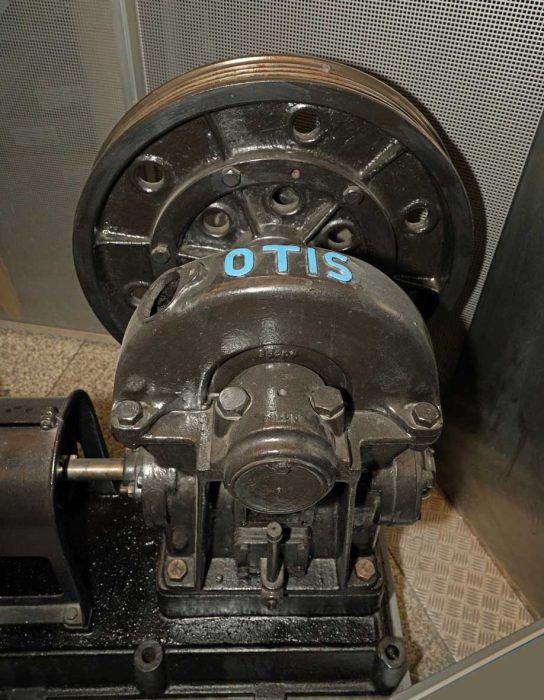
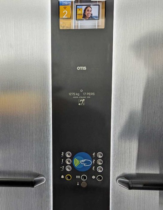

Gassner joined Otis to oversee the final installations of the new production facility and get it up and running. Not all is completed just yet; programs for assembling PCBs are still missing and will be created gradually as needed. One production line is currently running in the hall, so there is still plenty of room to add a second line in a few years, as the speed and accuracy of PCB production continues to increase.
The Path Ahead
The path to the production area took us to the first floor, where an Otis Gen360 platform resided, then across a busy and frequented courtyard on the factory grounds, and finally to the factory hall.
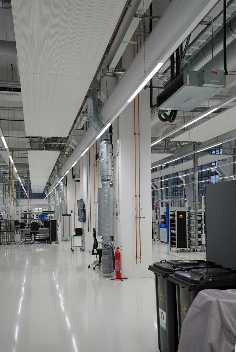
The hall was built in 1932 and is now a listed building, which makes it not particularly energy efficient. Its single-glazed glass, some of which still dates to the year of construction, is being added to with a second layer, and the hall is heated with black radiators. The temperature specifications are 19 to 26 degrees Celsius day and night.
The inside of the hall is a “controlled area.” The requirements for this clean-room technology can be found in ISO 14644. If the particle sizes are significantly above the values specified in the standard, the cleanliness is assessed according to VDA-19, and a so-called controlled area is created. This controlled area always guarantees low particle concentrations, constant temperatures and, if necessary, air humidity. Here, people’s access is also regulated to keep particles at a minimum.
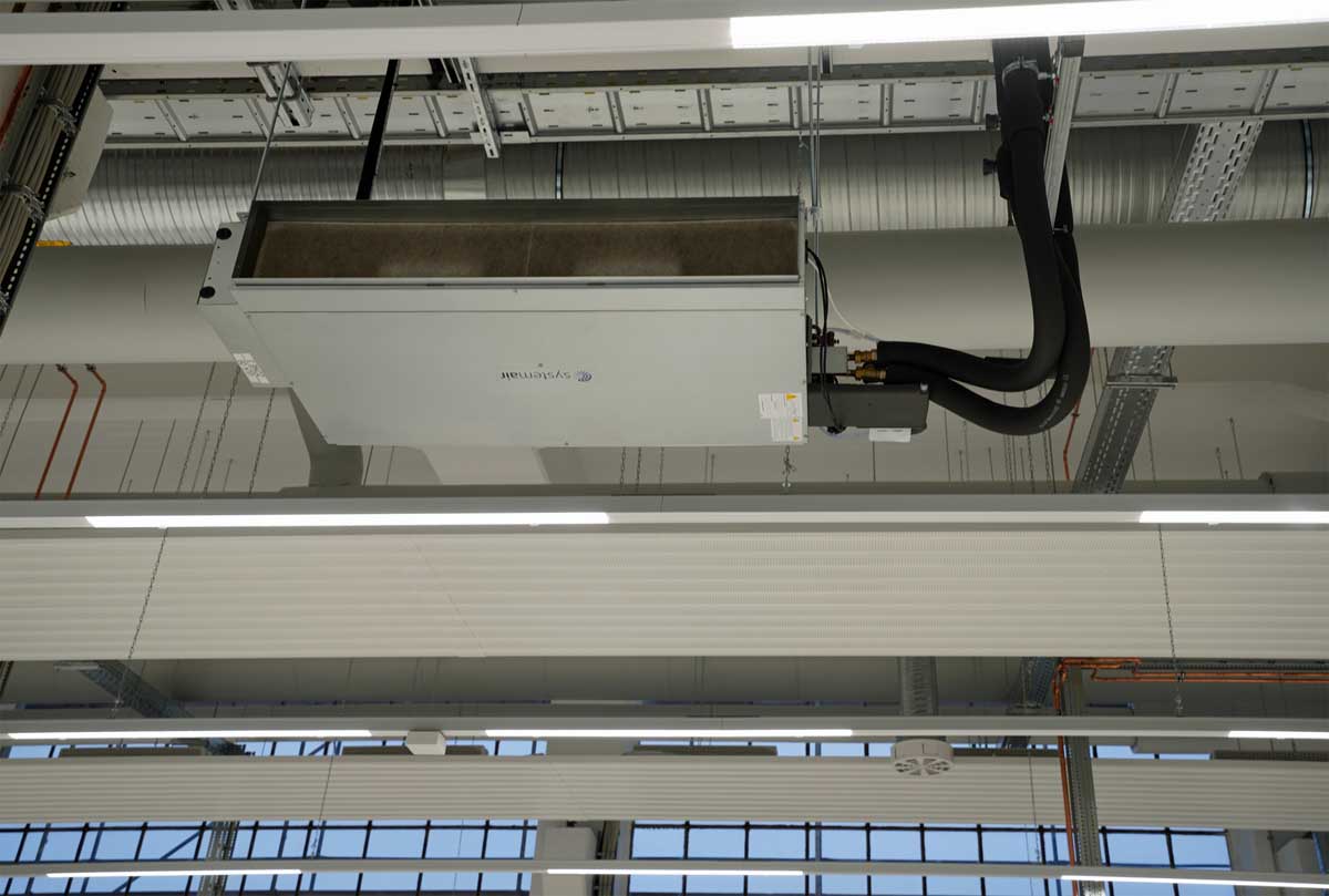
Dust in a production facility is generally not nice. Appropriate decentralized air purification units for air conditioning of the hall, i.e., filtration and humidification (not too dry), are suspended from the ceilings and are monitored and controlled by sensors. The air supply towers are located on the hall floor next to the support columns for the roof. In addition, the PCB printer itself is air-conditioned.
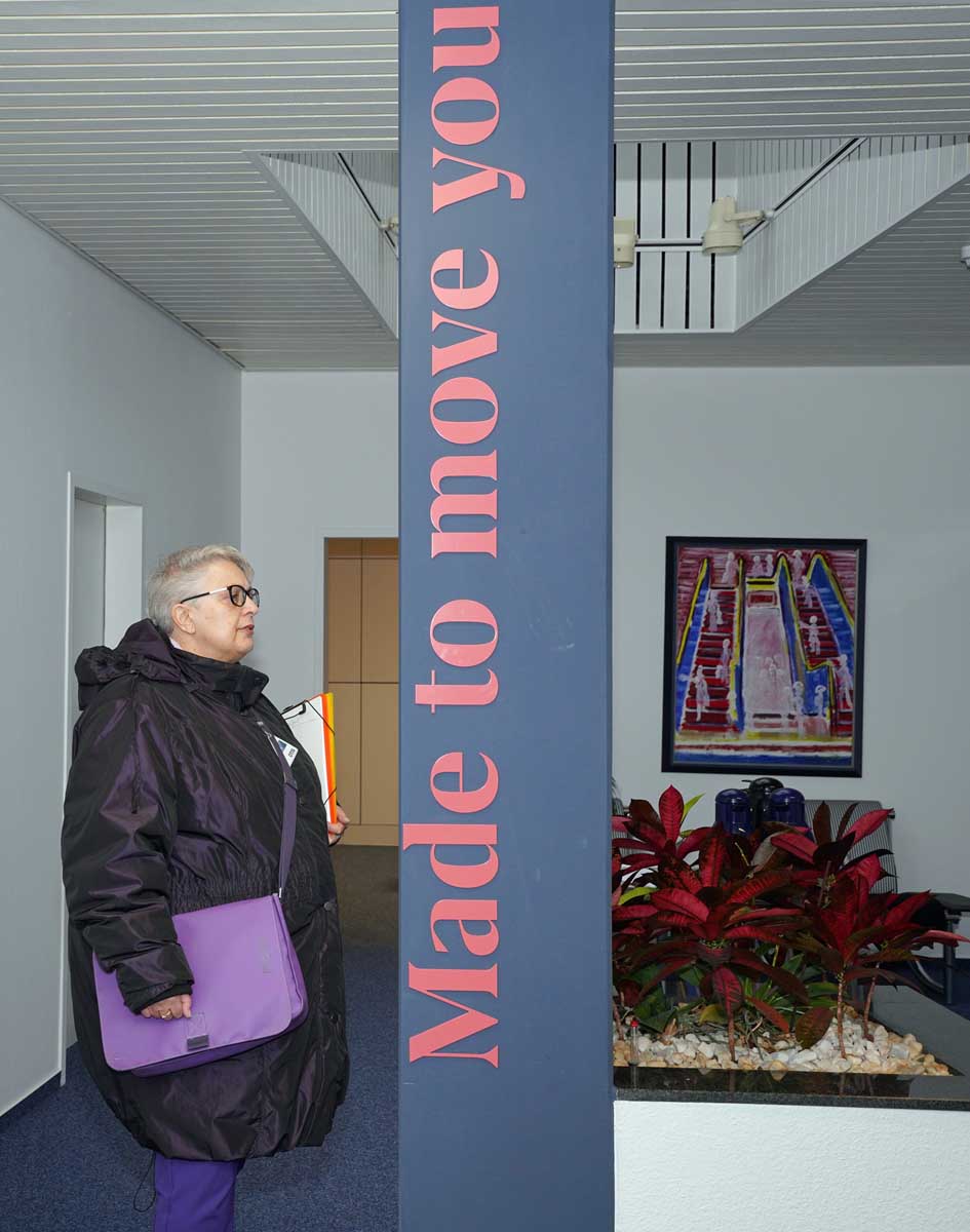
Electronic components have three main “causes of death:” electrostatics, lack of heat dissipation and corrosion. Entering the production area in the hall is laborious:
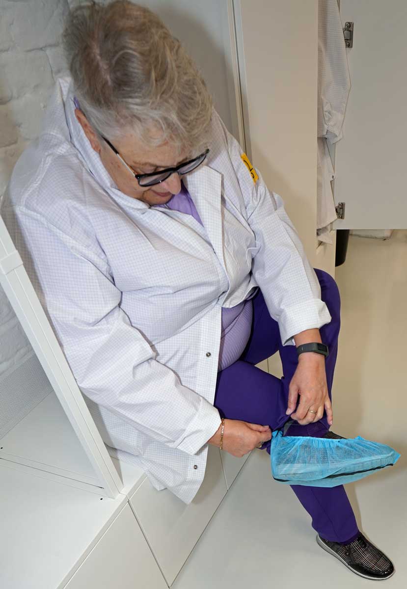
- Gowns are first pulled over clothing to prevent dust and fibers from being brought in.
- Then, to protect visitors against electrostatics, coatings are pulled over shoes. Electrical conductors in the form of metallized fabric strips are tucked from the floor under the overcoat, under the shoe sole and into the edge of the socks to create skin contact for grounding. The permanent employees wear electrostatic protective shoes, which last for about one year. This provides protection up to 1.3 Mega Ohm. The effectiveness of the covers is tested individually for each foot. The whole body is then tested before the access barrier is opened.
- The floor of the hall is also particularly complex and expensive. It is not only hard and durable but also electrostatic-safe.
Production Output and Input
The new production line currently offers the possibility to manufacture 68 different hardware products chosen from the product spectrum. This line is also devised to produce prototypes in runs of five together with the development department and then industrialize them. Also, all spare parts can be produced here, 68% within two calendar days. On the day of the tour, more than 1,000 boards were produced. This production was ramped up in stages of 25 and 100 pieces before the remaining quantity was produced to the full number in one run.
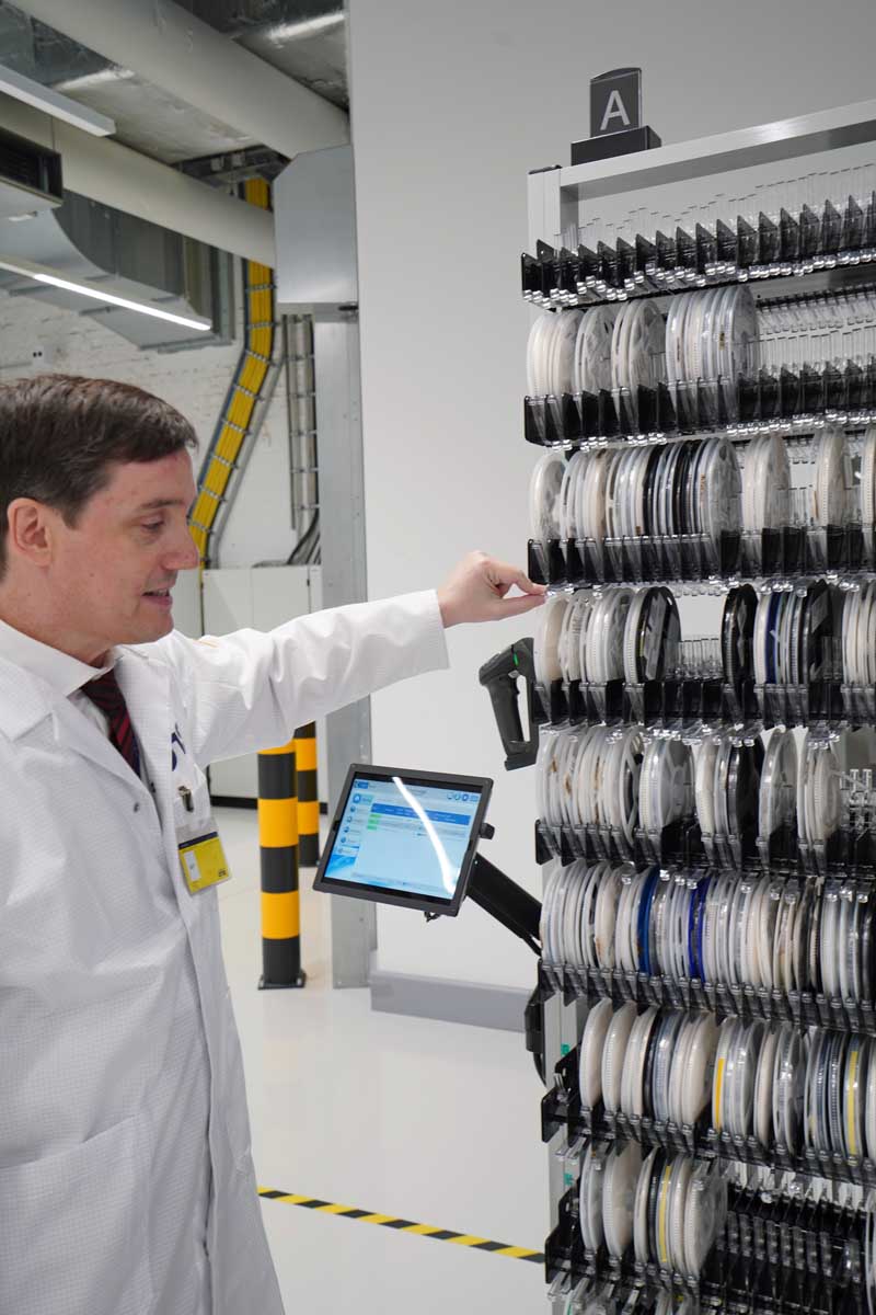
Tens of thousands of components are kept in stock on-site, which requires complex logistics. Among other things, these are stored in paternosters. This is a dynamic warehouse, which means that the ERP system finds the part randomly stored somewhere based on the barcode and the storage location stored in the system.
Smaller parts are stored in roll form on a shelf between the entrance and the first production step. The feeders are intelligent. They know how many parts are on a roll. To do this, an X-ray machine is kept on hand to count the parts on a coil. The result is noted on it as a barcode.
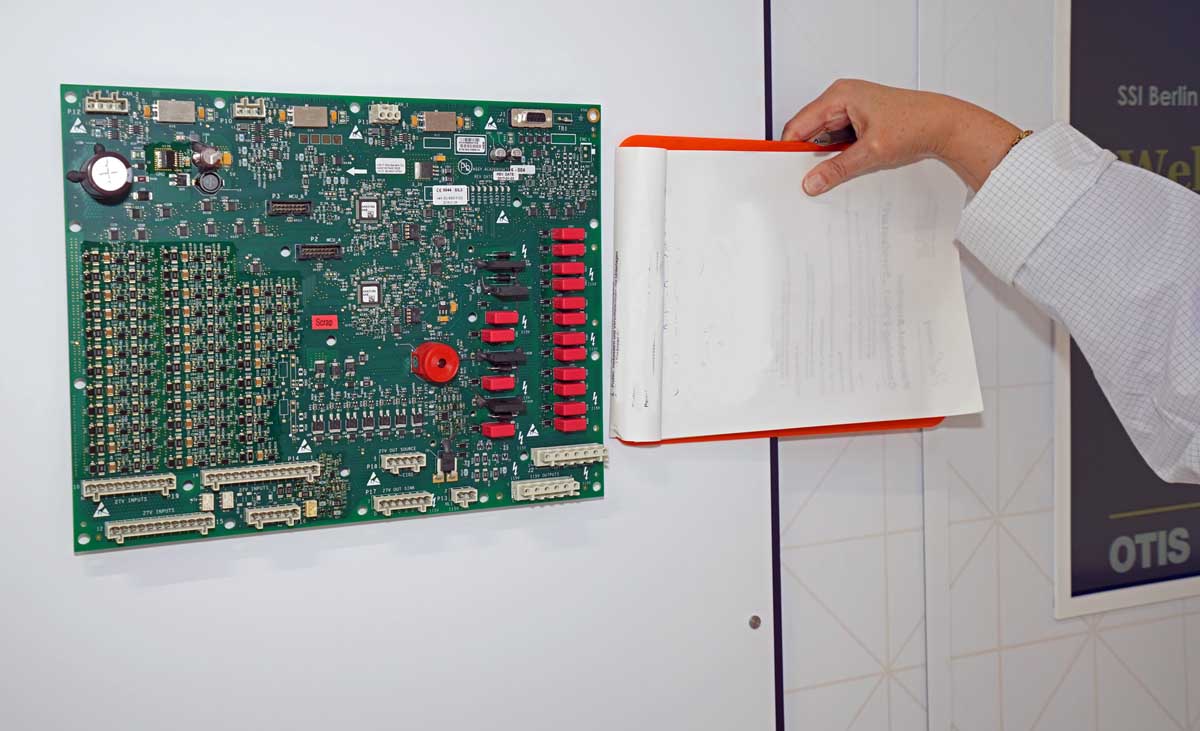
The boards from the production are double layered with up to eight layers. The size of the largest board on display is 500 mm long and 270 mm wide, with the longboard option allowing for even greater widths and lengths. The exhibited square board is used in high-rise and standard elevators. The higher the speed of the elevator, the more complex – and therefore usually larger – the board.
The boards manufactured in this production comply with IPC-A610 Class 3 because they are designed to last a lifetime in elevators such as the Otis Gen360 and are not regularly replaced every three years as in aviation. This is the same quality level that also controls an aircraft such as an Airbus or the ABS in a car, as well as being required in functional safety components of elevators. Lower classified are, for example, televisions in Class 1 or the cards for screens inside the cabin in an elevator with Class 2. Regulated in these levels are quality criteria such as positioning accuracy of the components, soldering quality, filling degrees of solder, insulation and penetration of wires through the board. Rejects are recycled.
Subcontracted supply, processing, packaging and shipping are taken care of by employees working in two shifts. These employees are highly qualified. The reconstruction was an opportunity to invest in electronic equipment and new automatic processes to eliminate manual errors. Particular importance is given to occupational safety. For example, automatic lifters are used for stacked PCBs.
Step by Step Through the Production of Printed Circuit Boards
Over a period of two hours, Gassner and your author walked through the individual production steps in the 1,800-m2 hall.
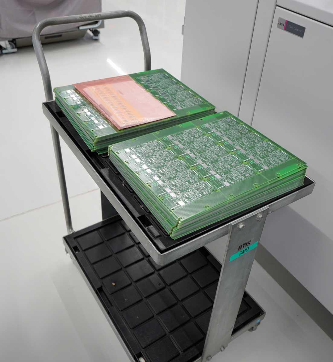
1) The “naked” PCB is coated green. More than 20 years of rot-proof stickers allow tracing back to the manufacturer, three of which are from Germany and three from abroad. Rigid FR4 circuit boards are supplied, consisting of glass fiber fabric impregnated with resin so-called prepregs (pre-impregnated fibers), which have been pressed with copper intermediate or outer layers.
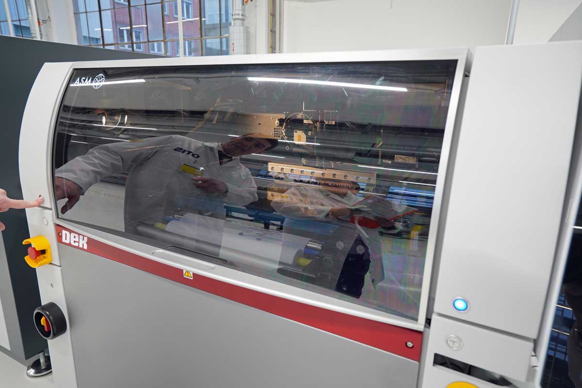
2) The serial number of the product is laser marked on the front and back of the board on the green solder lacquer. This is followed by solder paste printing working like screen printing. The board drives in; the solder paste moves over it. The copper is protected by the silvery soldering surface. The solder pastes are stored in a refrigerator. No-wash-flux solder is used, as in 80% of all cases worldwide today. The printer is from a German manufacturer.

3) The first quality assurance measure takes place: a solder paste inspection checks, by means of 3D photos and comparison with the specifications, whether solder has been applied to all solder joints and whether they are smooth.
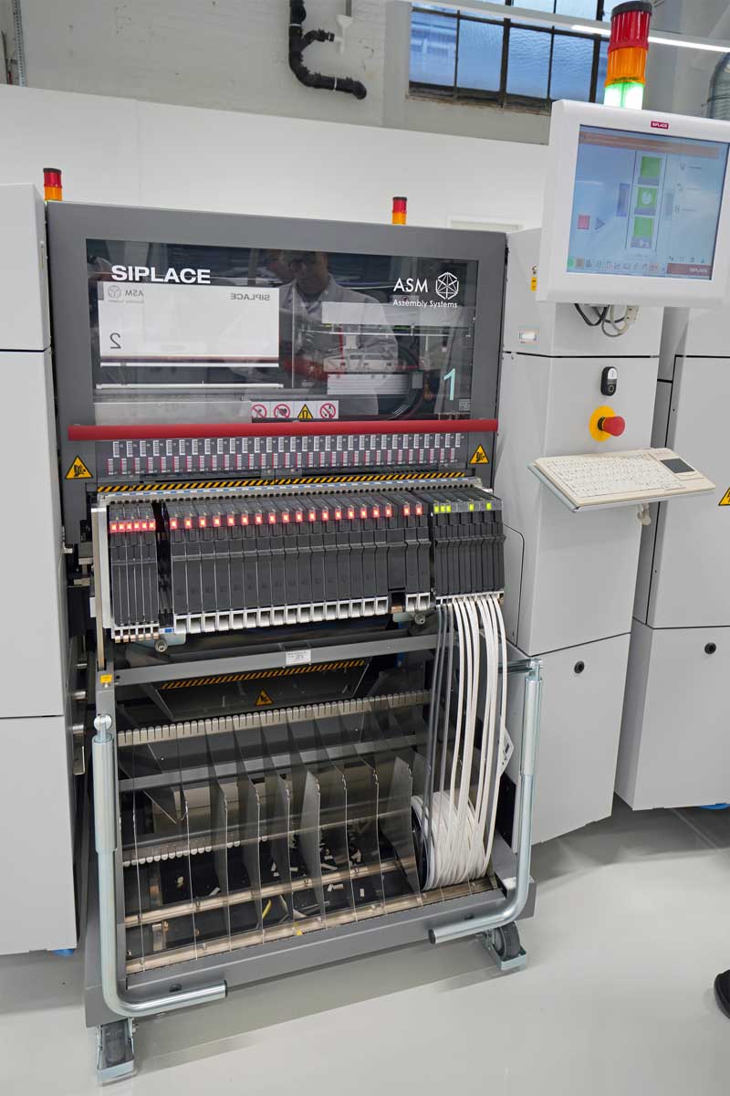
4) There are four placers in the line, each with two tray placement heads, i.e., eight moving slides in total. One of the placers has an additional single tray for extra-large components. The placers move at different speeds back and forth to the 59 (among experts one says 60, however) places. How many components are arranged and how they are arranged is the reason for the great complexity of the production. The pick-and-place machines are of German manufacture.
On the top of the board, the components are simply placed on the area covered with solder paste. Later, everything is heated, and the solder melts and the components are soldered. On the bottom side, the parts are fixed with glue and passed through a liquid solder bath, otherwise stuck-through components would fall off during the second soldering.
In the current production, the components were fed from five rolls of 8 mm after the machine read the barcode on the roll with the information about the component. Thus, in this case, 15 equally assembled but not yet soldered PCBs are created on one board, which is cut afterwards.
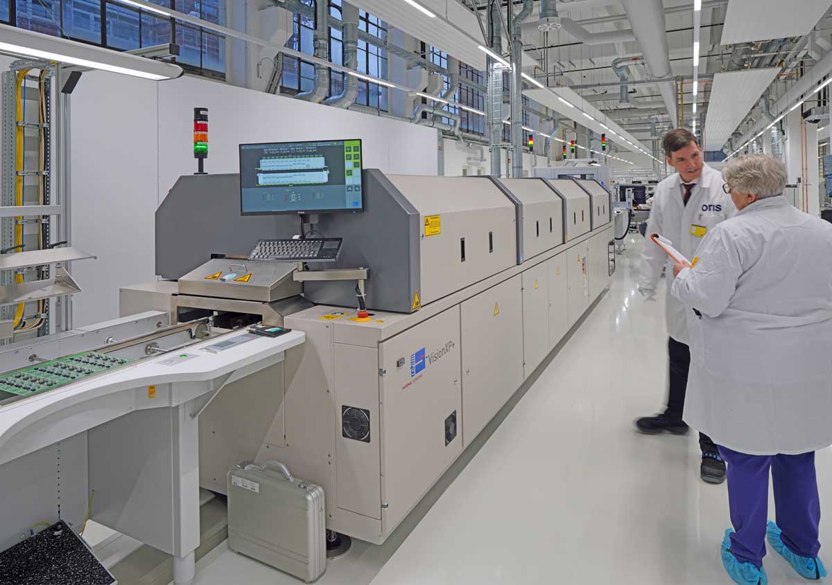
5) After a slow preheating, the tunnel oven heats the passing boards up to 240o C. One passage at a relatively constant speed takes 21 s in the case viewed. However, the sensor-controlled temperature profiles, i.e., when what is heated to what temperature and for how long, can be adjusted. Some areas are covered as needed.
Infrared radiant heat is used for the base load. A so-called “super mole” is always moved through the furnace to control the temperatures. Soldering takes place under inert gas. The moisture in the solder paste evaporates and is extracted by an explosion-proof fan.
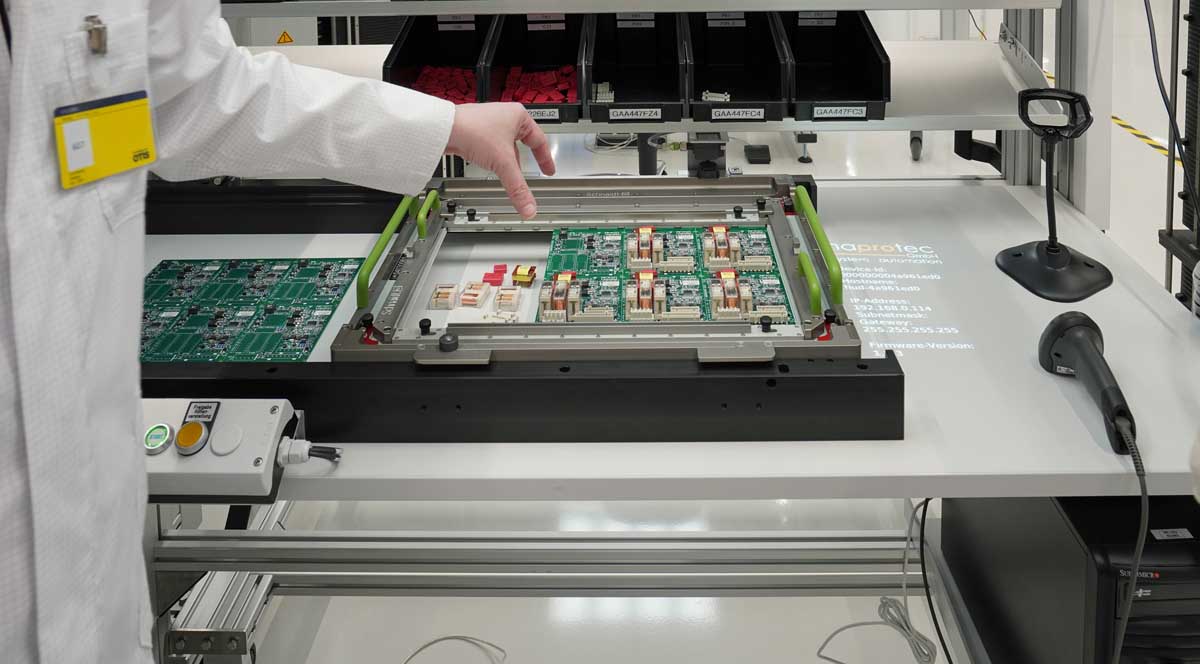
6) Boards with wired components, which later have to be re-soldered manually or automatically, are also locked out here on the basis of the board number. This is called through-hole technology (THT), in contrast to the previously used surface-mounted technology (SMT).
In the current production, there is a loudspeaker with two cables that later goes, “Ping,” in the elevator cabin to signal to passengers: “The elevator is there!”
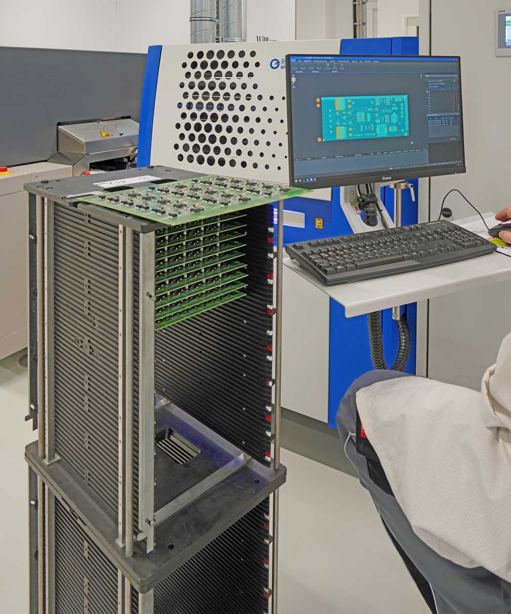
7) Time for the next quality assurance measure: automated optical inspection. The sample board is compared to a 3D photo to identify solder splatter, for example. A laser projects an image; a camera checks whether everything has been placed correctly. If errors are found, these also go into post-processing.

8) When everything is in place, the next step is to protect the board from corrosion and “creepy crawlies.” To do this, the board is coated with UV varnish in the coating unit and then dried on the conveyor to the collector at the end.
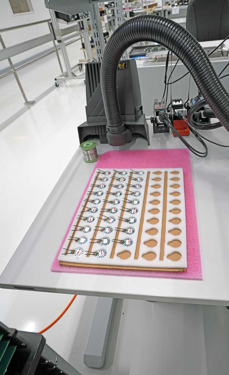
9) The four finishing stations offer the possibility of semi-automatic soldering by hand with liquid solder. For this purpose, two machines are kept ready to move the carrier in advance to the correct soldering position. Then, a wave generator wets the soldering point at the end of the wire. Due to the hydrolysis effect, the solder penetrates the hole and inner layers. Very small quantities are also processed here. Larger quantities are partly outsourced. During the inspection, a CAN bus board was being processed.
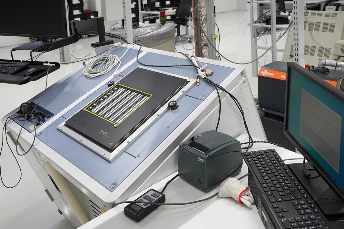
10) Quality assurance also follows here by means of optical inspection. Solder joints, for example, are checked for fillets.
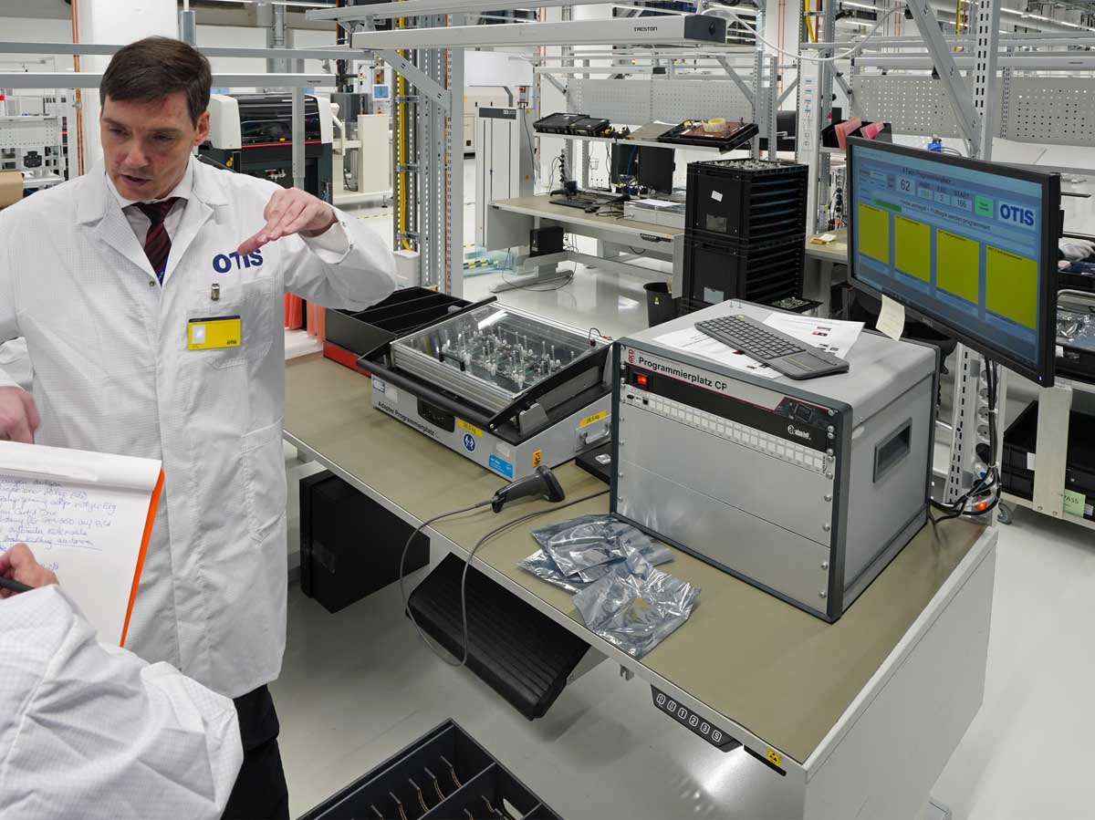
11) In the follow-up, it is also tested whether all circuits are functioning. This is done on an ICT (in-circuit tester). A needle adapter is placed on the board, which beeps the individual circuits for short circuits. Based on a current interruption, it determines whether the circuit is present as intended or not.
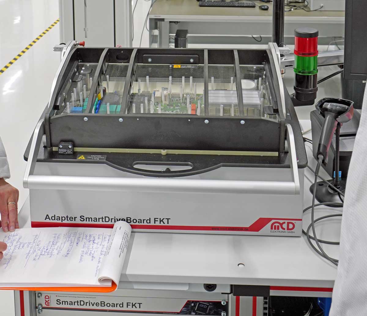
12) At the same time, software is loaded onto the board. Depending on how long the functional test of the circuits takes, the software packages are staggered (boot, basic or complete). Some components are delivered already pre-programmed. If there is not enough time, there is a separate software station for completion.
13) Near the end, there is the function tester, on which voltages are applied to the board from below. The question to be answered is: “Is the microprocessor making the right decision?” If the measured input quantity means, for example, “The cabin floor is 3 cm too high,” the board sends the signal to the elevator drive as a consequence: “Move!”
14) The board is also awarded a sticker that indicates, among other things, the origin of the hardware and software; and when and where the board was manufactured, programmed and sold.
15) Optionally, different boards are screwed onto each other or built into housings. During the visit, a display board was to be seen.
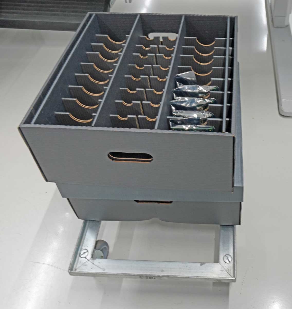
16) Now the board is ready for packing. The box during the visit was on its way to Paris. As an aside, Gassner noted that the Otis elevators installed and modernized at the Eiffel Tower use control systems that were once manufactured and programmed here in this hall.
Otis Facts
Otis is a global leader in the manufacture, installation and servicing of elevators and escalators. The company moves more than 2 billion people a day and maintains more than 2.1 million customer units worldwide – the industry’s largest service portfolio. Otis equipped many of the world’s most iconic structures like the Eiffel Tower, as well as residential and commercial buildings and transportation hubs. Headquartered in the U.S. in Connecticut, Otis is 68,000 people strong, including 41,000 field professionals, and is represented in more than 200 countries and territories. For more information, see Otis.com.
Get more of Elevator World. Sign up for our free e-newsletter.

