Practical Stress Behavior of Complete Rail Fastening Systems
Jun 1, 2011

This paper provides an example of conventional elevator design practice pertaining to rail clips, brackets and rail anchors as separate units.
This paper was presented at  Lucerne 2010, the International Congress on Vertical Transportation Technologies and first published in IAEE book Elevator Technology 18, edited by A. Lustig. It is a reprint with permission from the International Association of Elevator Engineers
  (website: www.elevcon.com). This paper is an exact reprint and has not been edited by ELEVATOR WORLD.
Key Words: Anchoring design, displacement, fastening system, failure load, pretension
Abstract
Conventional elevator design practice considers rail clips, brackets and rail anchors as separate units. Hilti conducted an analysis of how the complete rail fastening system acts under loading. This paper discusses the distribution of forces in the complete rail fastening system (rail clips, brackets and wall anchors) based on loads applied to the cabin rail. The results of practical tests disclose the failure mode of the various components of the rail fastening system and identify those that may cause a breakdown of the complete fastening system. Finally, the consequences an effective and cost efficient rail fastening system have for design are also discussed.
1.Introduction
The Elevcon2006 paper “Dynamic Design for Elevator Anchoring To Buildings” describes the design of anchors used to fasten guide rails subject to dynamic loading to concrete walls in elevator shafts. The design software proposed for this simplifies the situation by regarding the bracket connecting the point at which the forces are induced (rail) with the anchor as a rigid structure. Whether the rail fastening brackets frequently used in practice actually behave as a rigid system when under load can be called into question and this is pointed out in the Elevcon 2006 paper (Figure 1).
When the dynamic load is transferred to the anchor by a non-rigid system, the forces the anchor is required to transfer to the wall are different to those presumed in a design based on a rigid bracket. With a view to achieving optimum design of the guide rail fastenings on the shaft wall with regard to reliable transfer of the static and dynamic forces that occur, economical use of materials and efficient installation, the complete connecting structure, i.e. rail clips, bracket, connecting parts and the anchor, should be designed as a complete system. This was already indicated in the Elevcon2006 paper “Dynamic Design for Elevator Anchoring To Buildings”.
In 2009, in our laboratory which is accredited in accordance with the DIN EN ISO/IEC 17025 standard for the execution of mechanical-technological analyses of fastening methods and materials, we took the opportunity to assemble a complete rail fastening arrangement as a system and to subject it to dynamic and static loading at the rail in order to investigate the behavior of the system and the anchor in terms of elastic and plastic deformation as well as its failure mode and characteristics. A further goal of these investigations was to determine whether the anchor traditionally used for this fastening (HSA M12x100 in a hole drilled to a depth of 95mm) could be replaced by the HSA M12x80 in a 75mm hole, without failure of the anchor used for rail fastening.
2. Performance of The HSA Anchor Under Load In Shallow Holes
In the European Technical Approval ETA-99/0001 dated March 13, 2008, the minimum hole depth for installation of the Hilti HSA M12 is defined as being 70mm. One of the main points of the investigation of the rail fastening system’s failure characteristics was to determine the load limit for the Hilti HSA M12 set in a shallow hole. For this purpose, a minimum hole depth of 55mm was defined. The Hilti HSA is an expansion anchor that transfers forces to the concrete by way of a system consisting of a tapered section (1) which expands a sleeve (2). The sleeve then transfers compressive force (3) to the concrete (Figure 2).
The combination of the tension induced in the anchor and the compressive forces occurring at the expansion element result in propagation of pressure in a conical area toward the surface of the concrete. The greater the volume of concrete that can be “activated”, i.e. included in this conical pressure area (4), the greater are the forces that can be taken up before the point is reached at which the concrete fails and precisely this conical section breaks away from the main body of concrete.
The drilling depth of 55mm represents the geometric minimum. The expansion element is then located 15mm below the surface of the concrete. The so-called “effective anchorage depth” is 35mm. A minimum “activated” concrete volume is thus achieved. If the expansion element was to be positioned closer the concrete surface it would induce compressive forces into an area of the concrete that is, in practice, very inhomogeneous and of low com-pressive strength as the concrete so close to the form-work cannot be optimally compacted. The anchor would thus in all probability fail as soon as the specified tightening torque is applied at the installation stage.
A test series of five Hilti HSA M12 was set in the same concrete slab on which the rail fastening system to be tested was installed. The Hilti HSA M12 anchors were set in 55mm holes and tightened to a torque of 60Nm as specified in the European Technical Approval. The test load was applied by a hydraulic device and steadily in-creased until the anchor failed. In doing so, in addition to the load applied, displacement of the anchor was also measured (Figure 3).
As expected, the cause of failure in all five cases was concrete failure. The broken-out conical section of concrete is clearly visible in the photo. At a hole depth of 55mm, the volume of concrete that is required to take up the applied forces is very limited. The results of the tests showed a mean failure load of 22.8kN.
3. The Test Set-Up
The test set-up for investigation of the complete fastening system corresponded to the standard fastening method used for guide rails on a concrete elevator shaft wall. Concrete of the C20/25 grade was selected for the test and 19 days after casting it already had a compressive strength of 29.5 N/mm2. This is a situation very frequently encountered in new elevator shafts in buildings with up to 10 floors. The concrete found in higher buildings or in old buildings tends to be of higher strength. High-strength concrete is capable of taking up higher forces. The rail fastening bracket is a standard component consisting of two angle brackets which are clamped together in the middle by way of four M12 bolts and nuts located in elongated holes. The strength of the connection is defined by the frictional hold achieved between the two parts by the clamping force of the four bolts (Figure 4). The rail clips are also standard components. The M12 bolt/nut connections on the bracket are tightened to a torque of 72Nm. The HST M12x145 anchors used for this are set in holes drilled to a depth of 95mm. In practice, the standard anchors used are M12x100mm, also set in holes drilled to a depth of 95mm. The M12x145 anchors offering extra thread length were chosen for the test in order to allow attachment of the force measurement rings. The HST anchors were fitted with the supplied nuts which were tightened to a torque of 60Nm as specified in the European Technical Approval. The supplied nuts were subsequently replaced with the force measurement device.
The force measurement rings allow measurement of anchor pretension and also allow measurement of the force curve for the anchor during loading of the bracket. A tensile force acting toward the middle of the shaft and a shear force acting parallel to the wall of the shaft were applied to the rail. The tensile and shear forces acted directly on the rail and simulated the loads that the guide runners of the elevator car would apply when the elevator is in operation. The forces were applied by a hydraulic device. A displacement measuring device was fitted to the piston applying this force so that displacement of the bracket could be measured and recorded during the test.
4. The Impact of Tensile Loading on the Rail Fastening System
During the tensile loading test, a load that increased from 0 to 5kN was applied five times in order to simulate the stopping and starting of the elevator car during operation. In order to determine the cause of failure of the complete fastening system, the test load was subsequently slowly increased until failure occurred (Figure 5).
The test showed that this 5-peak cyclic load was taken up by the system without failure. Application of the load resulted in elastic and plastic displacement at the rail support point. At the maximum load (5kN) the maximum displacement was 2.5mm, with 0.5mm of plastic displacement remaining when the force was reduced to zero. During the load cycle, the force measured in the anchors rose only slightly (by 0.5kN) from the 12kN pretension applied during installation and returned to a value of 12kN after removal of the test load (Figure 6).
The rail fastening system failed at a maximum tensile load of 11kN. During this, the force measured in the anchors rose from the pretensioning value of 12kN to a value of 16kN. The cause of failure at 11kN was found to be the rail clips which were bent upwards to such an extent that the rail was pulled out of the anchorage. Up to the point of failure, the rail had been displaced by 9.5mm (Figure 7).
The results of the test showed that the fastening system survived the test load with plastic deformation of 0.5mm. They also showed that the fastening system reacted to application of the load by exhibiting elastic and plastic deformation. Accordingly, the load on the anchors was not as expected, i.e. not as presumed in the design.
5. The Impact of Shear Loading on the Rail Fastening System
In the next step, the rail fastening system was loaded by applying a shear load acting parallel to the wall of the shaft. The test load was again a 5-peak cyclic load rising from 0 to a value of 5kN. In order to determine the cause of failure of the complete fastening system, the test load was subsequently slowly increased until failure occurred (Figure 8).
Application of the shear load to the rail caused the bracket to bend in transverse and longitudinal directions to such an extent that the test had to be aborted. The test set-up used only a very short length of rail. In practice, longitudinal displacement of the rail would be transferred to the next bracket and to the base of the shaft and would thus be limited. In order to avoid longitudinal, displacement of the rail, a test set-up which applied the shear force directly to the bracket was selected. To simulate the lack of leverage in the system as a result of leaving out the rail, the maximum load was raised from 5 to 6kN from a starting point of zero during each cycle.
The test showed that the 5-peak cyclic load was taken up by the system without failure. Application of the load resulted in elastic and plastic displacement at the rail support point. At the maximum load (6kN) the maximum displacement was 6mm, with 2.5mm of plastic displacement remaining when the force was reduced to zero. Due to the leverage exerted by application of the shear force, the force curves measured for each of the two anchors were different. The force in the anchor under the tensile load resulting from this leverage rose by 3.0kN during the load cycle from the pretension force of 15kN and dropped to 8.5kN when the test load was removed. Due to the leverage effect resulting from the shear load, the other anchor was subjected to a compressive force which had no significant effect on anchor pretension (Figure 9).
The system failed at a maximum load of 12.7kN. As this occurred, the maximum force at the anchor in the tensile loading zone rose to 24kN. The rail fastening point was displaced by 25mm. Cause of failure was the bolted connection at the elongated holes in the two bracket parts. The two sheet metal parts were displaced toward each other (Figure 10).
The results of the test showed that the fastening system survived the working load with a plastic deformation of 2.5mm. They also showed that the fastening system reacted to application of the load by exhibiting elastic and plastic deformation. Accordingly, the load on the anchors was not as expected, i.e. not as presumed in the design.
6. Standard Anchor Design in Comparison
The design software commonly used for anchor fastenings regards the connecting structure between the points at which forces are applied, and the anchors, in a simplified form, i.e. as a rigid structure. This seems to make sense as the design details for the structure which would have to be known in order to take the influence of its deformation on the design of the anchor system into account, are often not known to a sufficient extent.
After obtaining these test results, the task is now to show, as a comparison, the anchor load values that the Hilti Profis design software calculates for the rail fastening system under investigation and the degree (in %) to which the loading capacity of the two Hilti HSA M12 anchors in 90mm holes is utilized. Using the geometric data for the brackets, the strength values for the steel and the concrete, plus the distance between the two anchors and the point at which the force is applied, a simplified model of the fastening system is produced. With this model, the forces acting on the anchors can then be calculated from the tensile and compressive loads of 5 kN in each case (Figure 11).
The calculation shows that when the tensile load is applied to the structure, each anchor is subjected to a tensile load of 5.3kN. Under application of the shear load, as in the test and due to leverage, anchor no. 1 is subjected to the highest stress with an additional tensile load of 5.6kN, while anchor no. 2 is situated in the pressure area of the base plate and is thus subjected to no load in addition to the pretension applied at the time of installation. The steel of the anchor under highest stress in the fastening system is thus loaded to 19% of its capacity. In contrast to the pull-out and conical concrete break-out failure modes which are concrete-related, capacity utilization reaches a maximum of 38%. With anchors, utilization of less than 25% of the steel’s loading capacity and less than 55% of the concrete’s capacity generally does not lead to fatigue problems.
The tests produced other results. In the tensile loading test under application of a load of 5kN, the maximum tensile load on each of the two anchors over and above the pretension load was 0.5kN. In the case of the most heavily loaded anchors in the shear loading test, the load in addition to the pretension remaining in the anchors after the first few load cycles was 9.5kN. The total load acting on the anchor through the combination of pretension and working load was discussed in the Elevcon2006 paper “Dynamic Design for Elevator Anchoring To Buildings”.
This confirms that deformation at the point of load application and at the structure between the rail and the anchor fastening has a great influence on the stress transferred to the anchor.
7. Conclusions
Various points can be derived from these test results and they are discussed briefly in the following paragraphs. It has been shown that changing over to the Hilti HSA M12 set in holes drilled to a depth of 70mm would not seem to be critical. Due to deformation of the rail bracket as a result of the stresses to which it is subjected, the forces acting on the anchors are not as expected, i.e. not as assumed by the design software, which makes its calculations on the basis of a simplified assumption that the bracket is fully rigid. Changing over to the Hilti HSA M12 in a shallower hole would have various advantages in terms of the health and safety of the personnel carrying out the installation work due to reduction of exposure to drilling dust and vibration. Furthermore, drilling shallower holes could also raise productivity due to shorter drilling times and a reduced risk of drilling right through (and thus damaging) relatively thin shaft walls.
Early warning of failure is provided by plastic deformation of the rail fastening system. In the event of displacement of the rail by several millimeters, the elevator car should come into conflict with the drive system for the elevator shaft doors and the elevator will switch automatically to “Service” mode. The service technician should notice the deformation of the brackets. He can subsequently deter-mine the cause of the overloading and take the necessary action to remedy it. The bent bracket can then be replaced and the rail re-aligned. The rail fastening system has inherent safety reserves in the event of partial failure.
Damage in the form of a bent bracket can be repaired at less cost than damage resulting from concrete failure at the anchor. As shown in figure 4 (photo of the failed anchor point), no further anchor can be installed at that point. The new bracket has to be fitted at a different position, which is more time-consuming and thus more costly than simple replacement of a bracket.
Whether it would be sensible to design the anchor and rail bracket as separate systems is another point for discussion. Designing the rail fastening as a complete system, including the anchor, would help to achieve a certain behavior in the event of failure. Furthermore, it would also help to achieve a cost-optimized complete solution with economical use of materials and efficient installation procedures.
At present, efforts are being made to combine the Hilti Profis anchor fastening design software with the Hilti Profis installation systems software. Hilti installation systems form a kit-like modular system of steel channels and connectors that makes it easier to produce versatile supporting structures for items to be fastened to the building structure by anchors. In the elevator field, Hilti installation systems are used for divider beams and door beams. The advantages of this are worldwide availability of standard solutions and flexible length adjustment through attachment by way of threaded bolts which can be fitted on site without need for cutting or jointing techniques that create sparks. These lightweight systems, which achieve their rigidity through the special design of the channel profiles instead of through material thickness, allow the lightweight beams to be brought into place in the elevator shaft without use of a crane or heavy lifting equipment. Hilti Profis installation systems software supports the simulation of elastic and plastic deformation when designing the structure. The com -bination of Hilti Profis anchor software and Hilti Profis installation systems software at which we are now aiming will allow optimum design of complete fastening systems that combine support structures and anchor fastenings.
8. Acknowledgements
I would like to thank my colleagues from the Center for Engineering Research and Technical Services department at Hilti. In particular, Jenoe Varga and Jacob Kunz for their support in the preparation of this paper.
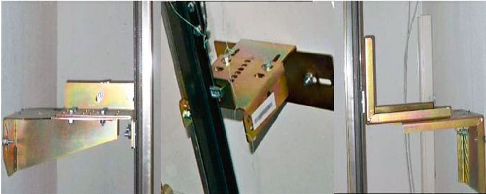
Figure 1: Standard rail fastening brackets 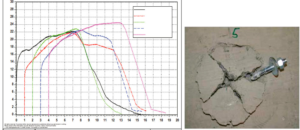
Movement (mm) Figure 3: Readings from the HSA M12 pull-out test and photo of the anchor point after failure 
Figure 4: Test set-up for load testing of the rail fastening system 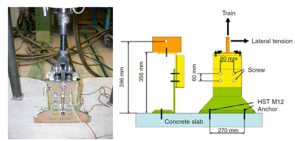
Figure 5: Test set-up for tensile loading of the rail fastening system 
Shift [mm] Figure 6: Test readings from the tensile loading of the rail fastening system 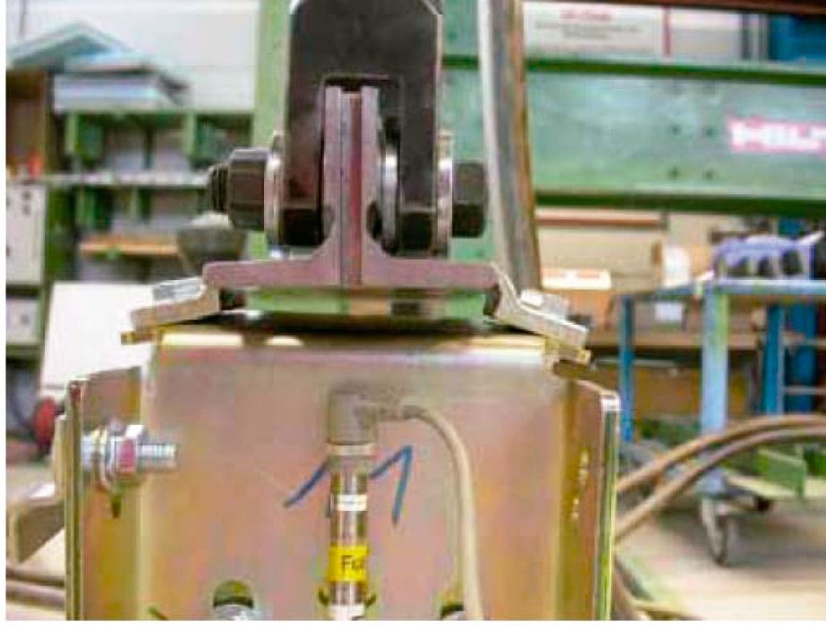
Figure 7: Failure of the rail fastening system under tensile loadin 
Figure 8: Test set-up for shear loading of the rail fastening system 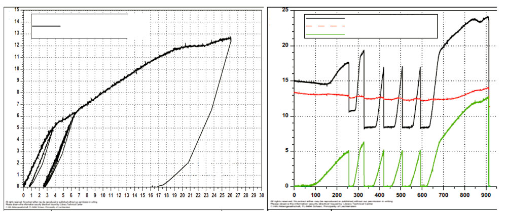
Movement console [mm] Figure 9: Test readings from shear loading of the rail fastening system 
Figure 10: Failure of the rail fastening system under shear loading 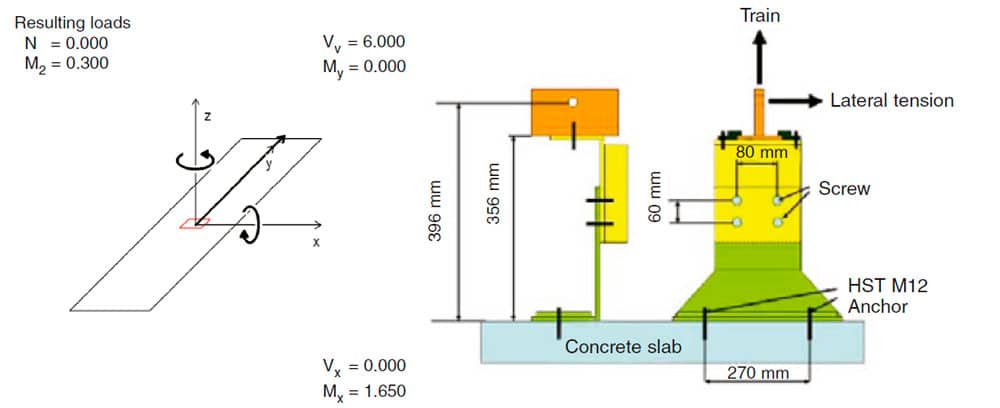
Mx = 1.650 Figure 11: Hilti Profis model of the rail fastening system
REFERENCES
(Hilti TWU – FSRL 29/ 08)
G. Hämmerle and Ch. König (2009). Tensile- and Shear Load on Brackets Assembly…; Tensile Loading on Hilti HSA M12/ 80 in Concrete…
(Elevcon2006 – Elevator Technology 16)
M. Merz (2006). Dynamic Design for Elevator Anchorings to Buildings
Get more of Elevator World. Sign up for our free e-newsletter.