Proposal and Specifications for a Titan Plunger Elevator
Jul 1, 2011

An examination of a typical late-19th-century service proposal.
Contracts and proposals for serv-ices have always been critical aspects of the elevator industry’s business operation. In a manner similar to that of today, 19th-century proposals for services provided the prospective client with the information needed to make a decision whether to purchase a given elevator. In the 1890s, the presentation of this information typically included both pragmatic details (type of elevator system, scope of work, responsibilities of the elevator manufacturer and client, etc.) and what might be termed promotional material that outlined the attributes, qualities and advantages of the company’s products. This article examines a typical late-19th-century proposal for service, which was prepared by an agent of Springfield Foundry Co. of Springfield, Massachusetts, on July 12, 1893 for a building in Keene, New Hampshire.
Titled Proposal and Specifications for a Titan Plunger Elevator, the document consists of three pages presented as a tri-fold brochure. The cover features an engraving that depicts the elevator pit, plunger, control valve and lower section of the car. Located between two pages of descriptive promotional text is the actual proposal for services, which consists of a series of specifications with blank fields that can be filled in with relevant information. In this case, the proposed elevator would travel between the first and second floors (a total rise of 9 ft., 3 in.) and have a lifting capacity of 225 lbs.
In the field designated for operating speed, perhaps in an effort to be as truthful as possible, the company’s agent simply wrote, “very slow.” It was, however, to be understood that this speed depended upon “the delivery to the elevator cylinder of a regular supply of water at a uniform pressure” of 55 psi. The estimated water usage per round trip was 9 gal. Springfield Foundry furnished the elevator car (specified as 43 in. by 28 in. in plan with an ash frame and maple floor), a 6-in.-diameter wrought-iron hydraulic cylinder, a wrought-iron plunger or piston (size not spec-ified), an iron-and-brass hydraulic valve (either 1.5 or 1 in.), a hand-control rope or rod and maple guide rails. The building owner was expected “to do all necessary mason-work and cutting of walls, floors, and timbers [and] to prepare and finish the elevator shaft and hatchways, which latter are to be about 44 in. by 30 in. in the clear.” The owner was also expected to “do all piping and furnish pipes of proper size” and to “furnish a carpenter to assist in erecting” the guide rails. The total estimated cost of the elevator was US$400.
The promotional text noted that the company’s direct-plunger elevator was named the Titan because of “its great power and efficiency for the quantity of water used.” It was also characterized as one of the “simplest, safest, most compact and convenient ever designed” and capable of “entirely fulfilling all requirements” for lifts of 50 ft. or less. Springfield Foundry claimed that its system was superior to competitors’ “on account of valuable improvements in both elevator and hydraulic design” that had been “introduced by our superintendent, one of the pioneers of hydraulic plunger elevators.” The company’s superintendent has been identified as James Gibbins; unfortunately, thus far, very little is known about this elevator “pioneer” other than his association with this company and his pursuit of four elevator patents.
The Titan hydraulic elevator was described as suitable for passenger or freight applications and appropriate for use in residences, hotels, dry-goods stores and industrial settings. The lifting capacity of Titan freight elevators ranged from 500 lbs. to warehouse elevators “capable of lifting wagons with horses attached.” Customers interested in seeing these elevators in operation were invited to visit the foundry, which employed two Titan elevators: one “for adjusting quickly and easily raising heavy castings under a suspension drill” and one for “raising pig iron and fuel to the cupola platform.” The elevator was equipped with an improved valve that prevented “pounding of the water and sudden jerking of the car.” An indicator for recording water usage could also be added to the platform.
In settings with low water pressure, the recommended solution was the use of a “direct-pressure tank” located in the basement. The other option was the use of a gravity tank (typically located on the roof); however, this system was not recommended because of the expense of running additional piping to and from the tank and the risk of freezing during the winter months. The Titan passenger elevator featured cars described as being “framed of hard wood, braced with iron and finished to suit the purchaser.” The finish could be “plain or elegant in style” and could employ cherry, oak or mahogany paneling, plush or leather upholstery, beveled plate glass mirrors and/or stained glass, and brass or wrought-iron screens. The cars could also be equipped with an annunciator, and either a gas light fixture or an electrolier (an electric light designed to resemble a chandelier). Hotel passenger elevators featured “lower decks” designed to carry luggage.
Customers who required an elevator capable of reaching heights above 50 ft. were asked to consider Springfield Foundry’s Atlas Hydraulic Screw Elevator, which was described as “perfectly adapted to all variations of height, speed, capacity and pressure.” Although this system received only a brief reference in the Titan proposal, further investigation has revealed that it was also designed by Gibbins, who pursued two patents associated with its design: Hydraulic Elevator Engine (U.S. Patent No. 337,056, March 2, 1886) and Elevator Engine (U.S. Patent No. 454,012, June 9, 1891). The elevator engine was an intriguing version of a horizontal hydraulic engine; however, instead of the typical plunger connected to a series of multiplying sheaves, the plunger pushed a “nut” along a screw shaft. The plunger, which was composed of two horizontal pis-ton rods, moved a crosshead that contained a nut or threaded collar that, in turn, imparted motion to a screw shaft. The screw shaft was linked via a geared connection to the winding drum, and thus the rotation of the shaft raised or lowered the car.
Springfield Foundry’s Proposal and Specifications document sheds light on normative business practices of the 1890s as practiced by regional elevator companies. The clear delineation of what was offered by the manufacturer and what was required of the customer describes the dynamic partnership that elevator construction often required in this period, particularly in the case of smaller manufacturers building elevators for clients in small-town America (in 1890, Keene, New Hampshire, had a population of approximately 7,500). The topic of elevator construction, how it was integrated into the building process and how it changed over time will be the subject of a future article.
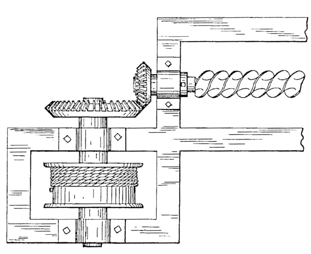
Atlas Hydraulic Screw Elevator: “the geared connection between the screw-shaft and the winding drum” (as depicted in Gibbins’ 1886 patent) 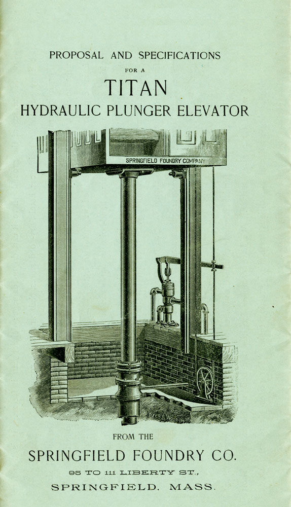
Cover design, Proposal and Specifications for a Titan Plunger Elevator, 1893 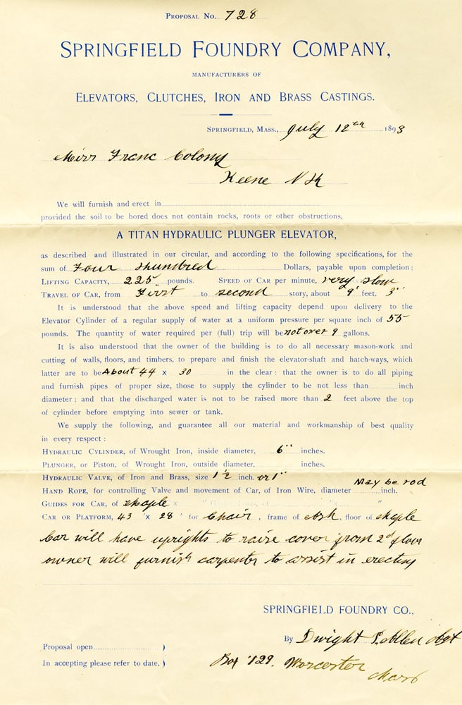
Proposal and specifications for a Titan elevator for a building in Keene, New Hamp-shire, 1893

Get more of Elevator World. Sign up for our free e-newsletter.


