Reading Electronic Schematics
Nov 1, 2016
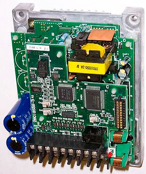
How to understand and create tools essential in troubleshooting and comprehending electronic devices
In electronic equipment, there has been a continuous move toward more complexity and increased miniaturization. These trends make troubleshooting and diagnosis ever more difficult. For an elevator motion controller in a public building, the stakes are high, because any outage, even for an hour., can equate to great expense. Additionally, there are health and safety issues that intensify the scenario. Consider a bank of elevators in a healthcare facility paralyzed by the failure of a single discrete component soldered in place on one of many circuit boards.
Repair technicians can open enclosures and visually inspect their contents, often in vain. Sometimes, a burnt device, wire or termination will reveal the point of failure, but more often, the circuitry will just stare back at you. Diagnostic test equipment may point the way, but you still have to know where to look. Without doubt, the greatest single asset in working through such enigmas is the schematic diagram. In a job interview, the applicant will be asked, “Can you read schematics?” The answer is not always clear-cut: some schematics are models of clarity and convey the intended information efficiently and without ambiguity, while others are muddled and disorganized.
Diagrams
Manufacturers generally supply three types (with subtypes) of diagrams as part of the documentation that accompanies electronic equipment. Besides schematics, there are pictorial and block diagrams.
Pictorial
Pictorial diagrams consist of photographs or drawings to scale, showing the components as they are physically situated on the chassis or circuit board. These graphics are very helpful after a repair has been made in successfully getting everything back together without damage. In electronics, there is often a significant mechanical aspect to the work, as when a motor/pump unit has to be taken apart for repairs and then reassembled. An exploded view, a type of pictorial diagram, is helpful.
When dealing with a complex and challenging electromechanical assembly and there is no pictorial diagram available–a good approach is to take high-resolution digital photographs of the equipment at various stages of disassembly. These can be helpful in reconnecting wires properly. (A misconnected wire has been known to cause elevator door interlock failure.)
Block
Another diagram usually included in the manufacturer’s documentation is the block diagram. Here, individual components and circuit wiring are not depicted. Instead, major stages in the electronic equipment are shown with single lines indicating power and information flow among stages. This type of diagram provides an excellent overview of the equipment and is immensely helpful as a first approach in failure assessment and diagnosis.
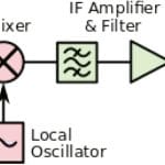
Since the invention of the superheterodyne radio receiver (Figure 2) in the early 20th century, this design has dominated radio communications, and it is used in television (TV), as well. An oscillator, tuned in synchronization with the radio-frequency (RF) filter that selects broadcasts from a range of frequencies, supplies electrical energy that beats in the mixer with the RF signal, dropping it down to a more manageable intermediate frequency. This signal is subsequently amplified, demodulated and again amplified in audio stages and, finally, fed to the speaker.
Schematic
By far, the most helpful single item in the manufacturer’s documentation is the schematic diagram, accompanied by a parts list. This may consist of a single page or many pages, often spiral bound so that it will lay flat on the workbench. When a schematic diagram, because of size and complexity, fills multiple pages, each page will have terminations that show interconnections. This may seem to be a source of confusion, but it is actually reasonably user friendly, because each page contains information relating to specific functions, so the focus is often limited to a single page.
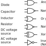
A schematic diagram, as opposed to a pictorial diagram, does not picture the components as they actually appear. Instead, symbols, conforming to national and closely related international standards, are used. These symbols are wonderfully intuitive, expressing not the way the components look, but how they work. Consider, for example, the schematic symbols for resistor, capacitor and inductor.
The schematic symbol for a resistor is based on a time when the component was formed from a long wire segment wrapped in such a way as to avoid having inductance. Currently, most resistors consist of carbon and other materials combined so as to have the required resistance, though wire-wound resistors are still used in high-precision applications. When current flows through a resistor, the voltage is dropped, and the excess electrical energy is dissipated in the form of heat. The dissipated heat is proportional to the square of the amount of current times the resistance, which is expressed as I2R. Engineers speak of I2R loss in any device or conductor that has resistance.
The schematic symbol for a diode has an anode and cathode, and it is evident from looking at the symbol that current will flow in one direction when it is forward biased, but not in the other direction when it is reverse biased. The schematic symbol for an inductor clearly conveys the idea of a coil of wire. An air-core inductor is shown. If one or more lines are added parallel to the windings, the device has an iron core. The symbol for a capacitor is also quite intuitive. The two parallel plates are shown with leads affixed, and there is a gap between them corresponding to the dielectric layer. A real-world capacitor may be rolled to form a cylinder, but the symbol conveys the idea schematically.
The symbols for digital gates become increasingly intuitive with exposure. Notice that a gate may have one or more inputs but always a single output. The round circle at the output denotes the input is inverted in the device. The concave line at the input shows the device is an OR digital logic gate or one of its derivatives.
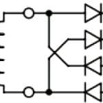
Figure 4 shows input power (typically standard 120-VAC house current) on the left and unfiltered pulsating DC output on the right. Four diodes are arranged to provide full-wave rectification without need for a center wrap. The symbol for the resistor is a variant. The schematic shows correct polarization for the two pairs of diodes. A power transformer invariably has an iron core, as shown.
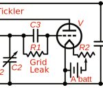
Figure 5 shows a regenerative receiver, an early type of radio that followed the crystal set and preceded the superheterodyne. It is still built by students as an educational project, and its output is more than sufficient to drive headphones. Enhanced gain is achieved by feeding a part of the output back into the input of the single-tube amplifier. Coupling is provided by two air-core inductors. One slides inside the other, moved by the operator, thus regulating the amount of regeneration.
At the signal input, one end of the primary coil is connected to ground, while the other end terminates at an antenna through a variable capacitor. Notice the capacitors are labeled “C1,” “C2,” “C3” and “C4.” They and other components are usually listed in an accompanying table giving specifications. The vacuum-tube envelope is shown as a circle with internal elements, a filament, a grid and a plate represented by conventional symbols. Power supplies (in this case, batteries) are sometimes terminated at the tops and bottoms of the schematic. Here, they are located within the diagram.
With practice, increasingly complex schematics can be read so that the purpose of the various components becomes clear and power and signal flows understood. Well-drawn schematics adhere closely to these standards. Any improvisation or attempts to stylize the symbols is definitely out of place and will impede efficient and accurate interpretation. Complete catalogs of schematic symbols, including the many variations of semiconductors, can be found on the Internet, and it is recommended that you print, post over the workbench and save in the computer a chart of these symbols.
In addition to conventions for individual schematic symbols, there are conventions for how the overall layout is realized. The schematic diagram does not relate to the real-world position of components on a chassis or circuit board. The intent is to show the logical and electrical connections. In the schematic diagram, component symbols are positioned with respect to power and information flow, and conform to conventions. Knowledgeable electronic technicians understand these conventions. With experience in analyzing schematics and comparing them to the actual circuit boards and overall electronic equipment, workers internalize these conventions so schematic diagrams make sense right from the start.
At one time, virtually all elevators were powered by DC motors, because the speed of an AC motor could not be readily controlled. The mid-20th-century invention of the variable-frequency drive (VFD) was a great innovation, because, with fairly simple circuitry, it permitted automatic speed, direction and torque control of a standard AC induction motor.
The schematic shows how it works. Three-phase utility power, often 480 V, is supplied by a branch circuit to the unit, typically housed in a well-ventilated metal enclosure. Each of the three hot legs is center-tapped into a pair of diodes. All six diodes are polarized in the same direction, and the DC output from this rectifier section is fed to two heavy conductors, known as the DC bus. A capacitor is connected across the DC bus for the purpose of filtering out ripple.
The DC bus conveys power to the inverter section of the VFD. Since this is the output, it is depicted at the right of the schematic, but the actual layout within the enclosure may differ. The intent of the schematic is to show logical function and electrical connections, not physical locations of the components. It is the job of the technician to locate components and find circuit nodes so measurements can be made.
The DC power moves across the DC bus to the six output semiconductors. Notice that the signal inputs, coming from the elevator motion controller, are not shown beyond the semiconductor leads, although the three-phase power output to the motor is shown. The technician using a multimeter and an oscilloscope will know what to look for by reading the schematic. Often, schematics show the proper voltages at various test points, and for a TV schematic, small graphics with oscilloscope traces are shown at critical points. On the DC bus, we want to see a pure unvarying direct current free of ripples. At the VFD output and the three motor terminals, look for balanced, pulse-modulated current free of harmonics.
Needless to say, these are very high voltage levels with large amounts of available fault current. Extreme caution should be taken to avoid shock and arc flash. Before working on this sort of equipment, the technician should receive instruction and understand how to deal with potential hazards. Safety interlocks, guarding and grounding must remain in place, and after repairs are completed, care must be taken so new hazards are not introduced. Terminations need to be torqued to specifications, and all cautions in the manufacturer’s documentation must be observed.
Consulting the schematic and considering the symptoms exhibited by the equipment under investigation, it should be possible to ascertain the general, if not the exact, location of the fault. Referring to the schematic, once the general area of the fault has been located, several techniques are available for pinpointing the problem. For example, a microprocessor that is abnormally hot is probably damaged and not functioning. If it is not warm at all (i.e., it is at room temperature), the device is not receiving, or it is not passing current. If the working temperature is abnormal, either the microchip is bad internally or a peripheral is faulty (usually shorted or open), and electrical energy is not going where it should.
Troubleshooting
Diagnosis becomes more difficult when operational faults are intermittent. This may be caused by a small, virtually invisible, crack in a device or conductor that expands when critical temperature is attained. It is sometimes possible to apply a small amount of heat to a questionable component or conductor so as to bring out the fault. A cooling spray, made for the purpose, will sometimes temporarily restore operation for diagnostic purposes. The schematic diagram will always lead you to the fault.
What is difficult (sometimes a little difficult, sometimes very difficult) is locating the components, as shown on a schematic, on the actual printed circuit board or chassis. With increased miniaturization, following printed conductors on the reverse side of circuit boards and locating and identifying device terminations and circuit nodes have become increasingly difficult. Device locations on a circuit board are determined by many factors, including characteristic impedance of the printed circuit traces, positioning of devices to mitigate thermal and electromagnetic effects, and so on.
It is very easy to damage nearby devices and/or the circuit board itself when desoldering and soldering components. If an elevator is down in a public place, the best option may be to replace one (or more) entire circuit board(s) to restore operation quickly. However, this depends upon availability. Also, be aware that:
- Entire circuit boards are very expensive. This is because, for specialized equipment, they are manufactured in relatively small quantities.
- Because they contain large populations of metal–oxide–semiconductor field-effect transistor-like insulated gate devices in complementary metal–oxide–semiconductor configurations, modern circuit boards can be instantly ruined by very small amounts of static electricity. A serious problem is that circuit boards damaged in this way show no visible sign of damage. The technician may assume that since the substitution failed to solve the problem, the fault must lie elsewhere.
- A circuit board may be damaged by excessive voltage or heat that comes from outside of it. A replacement board will, sooner or later, suffer the same fate. A related problem arises when a cooling fan, perhaps because of a bad bearing, power supply, sensor or control wiring, fails to perform its cooling function. Also, look for blocked or clogged cooling vents or high ambient temperature.
For the above reasons, it sometimes makes more sense to replace an individual component on a circuit board. This is especially true when you are not dealing with an outage in a public place. For example, you may have replaced a bad circuit board and want to fix it as a spare. There are online tutorials and print books and articles available that cover soldering techniques and circuit-board repair in detail.
Creation
You may have occasion to draw a schematic. With a good understanding of the conventions heretofore discussed, you can create a schematic and scan it for the purpose of emailing it to colleagues or to a manufacturer’s technical support for consultation.
A schematic can be drawn using ordinary drafting tools and techniques. This process is time consuming, and, while the results may be acceptable for some applications, they leave something to be desired if one is preparing a manufacturer’s documentation or promotional materials. For applications such as these, there are computer programs that, if skillfully implemented, will yield superb schematics with built-in compliance to all the conventions.
Examples
Digikey, a large electronics components supplier, offers a free online schematics and diagramming tool at www.digikey.com. Click on “EDA & Design Tools” then “Scheme-it” then “Try It Now.” The “New Project” window comes up, and from there, you can see how the program works. A screen that looks like a sheet of graph paper with a list of devices in a vertical column (on the left) appears. For example, there are 29 types of diodes. Any of them can be dragged into the project, rotated, connected with lines that represent wires and arranged as desired. The end result is a finished schematic that can be given a name and saved as a file.
Easily Applicable Graphical Layout Editor (EAGLE) is a complete electronics design system that has become the tool of choice for electronics design professionals. In addition to permitting schematic capture, it is a printed–circuit–board (PCB)layout editor and auto router. It also contains computer-aided-design and bill-of-materials tools.
EAGLE has a steep learning curve. In this, it resembles Adobe Photoshop. To become proficient, expect to devote lots of time and effort. To begin, choose and download the desired version, based on budget and needs. The free EAGLE Light enables the user to evaluate the program and learn what is involved. It works in Mac, Microsoft Windows and Linux operating systems. Users can take advantage of a very large expandable library of components, which can be further modified and customized. Symbols representing electronic components are moved onto the page and arranged to create the desired circuitry. Additional capabilities include the ability to translate the schematic, with a click, into a PCB layout with auto routing. The product can be saved as Gerber, Post Script, Excellon or Lieb & Meyer drill files, as required by PCB fabrication companies.
If the goal is to create schematics for print or to communicate with colleagues, EAGLE Light’s functionality is sufficient. However, this version’s maximum PCB size is 4 X 3.2 in. (though still sufficient for many applications). In creating schematics, the Light edition permits only one sheet per project, so it is not possible to divide a large project into separate schematics with links between the sheets. To go beyond these limitations, it is necessary to purchase one of the more advanced versions.
EAGLE is built upon a “Control Panel,” which permits access to its many features. It is here that the user accesses libraries of components, specifies design rules (such as track spacing) and moves to more of the program’s features.
Under “Projects,” there are two files: “Schematic” (.sch) and “Board Layout” (.brd). It is necessary to have both of these open simultaneously when working on a program so they remain synchronized.
Conclusion
Electronic schematics are at once challenging, yet user friendly for the technician who cares to use them. Without schematics and other documentation, the task at hand is far more difficult, and the likelihood of success greatly reduced.
- Figure 1: A pictorial representation of a VFD
- Figure 2: Block diagram of the signal flow in a superheterodyne radio receiver: power flow is omitted for clarity.
- Figure 3: Schematic symbols for electronic components
- Figure 4: A schematic of a full-wave rectifier
- Figure 5: A schematic of a regenerative receiver
- Figure 6: Schematic diagram of a VFD
- Figure 7: The EAGLE “Control Panel”
Get more of Elevator World. Sign up for our free e-newsletter.

