Rectification
Dec 1, 2017
An examination of the necessary components for such elevator-related technology as VFDs
Thomas Edison’s first electrical distribution systems starting in lower Manhattan, New York, were DC, but AC quickly gained market share and, before long, prevailed. Developed by Nikola Tesla and George Westinghouse, the AC format had some key advantages, which is why it has become the universal standard. For one thing, AC can be easily stepped up for efficient distribution or stepped down for user-friendly power at the downstream end. The only device needed is the relatively inexpensive transformer with simple input and output connections. The ratio of input to output voltage is the same as the ratio of the number of turns in input and output windings. A step-up transformer does not provide free energy, because the lower voltage winding carries a higher current flow in amperes.
Learning Objectives
After reading this article, you should have learned about:
♦ Comparison of AC and DC for different applications
♦ Principal uses of DC for elevators
♦ Circuitry and outputs for various types of rectifiers
♦ Types of filtering
♦ The anatomy of a VFD
Another critical advantage of AC is that, compared to DC, there is less of a problem with corrosion. Whenever electrons cross the boundary where two unlike metal conductors join, and, to a lesser extent, when they are the same metal, oxidation occurs, and a less-conductive barrier grows. This is due to an inevitable electrochemical reaction. Anyone who has dealt with corroded automotive battery terminals has had experience with it. When the electrical energy is AC, due to the changing polarity, the chemical reaction continuously reverses, tending to cancel the accumulation of corrosion, another advantage of AC.
The AC delivered to home, office or factory is suitable for lighting, heat and other resistive loads, and it works for AC motors, including the ubiquitous induction motor, as well as the less common synchronous AC motor. But, there are many applications where DC is needed. Electronic equipment is everywhere, from audio, video and all kinds of gadgets in the home, to data networks and telephone systems in the office, to programmable logic controllers and control systems on the factory floor, to mention a few examples. What they all have in common is absolute dependency on semiconductor devices. If you count every discrete semiconductor, plus such devices within integrated circuits, they undoubtedly number in the high trillions. What most of them have in common is that they require DC power to operate. This can be supplied by a battery, but, very often, a DC power supply is used.
The DC power supply can be within the equipment enclosure or built into the power cord that plugs into an AC receptacle. Either way, these power supplies have certain elements in common. First, the premises power is usually applied to the input terminals of a step-down transformer. If the input is 120 VAC, and if the primary winding has 500 turns and the secondary winding has 50 turns, the output will be 12 V, a very usable voltage for many electronic circuits. (The output voltage would be slightly less because of magnetic and electrical losses in the transformer, as measured by its efficiency percentage.) The secondary winding may have one or more center taps, providing various lower voltages as needed throughout the equipment. Also, it is possible to incorporate a voltage divider, made up of a resistor network, to provide auxiliary voltages.
The next element in the power supply is the rectifier, which converts the AC to DC. In low-power applications, this is a fairly inexpensive device composed of one or more diodes. To begin with the simplest, though not the most effective, the half-wave rectifier consists of a single diode in series with the load, or, in the case of three-phase power, three diodes, one in each leg.
The essence of a diode is that when it is forward biased, it conducts, and when it is reverse biased, it does not conduct. By definition, forward biasing exists when a positive voltage is applied to the anode and negative voltage is applied to the cathode. Reverse biasing exists when negative voltage is applied to the anode and positive voltage is applied to the cathode.
When a single diode (three diodes for a three-phase circuit) is placed in series with the power source and load, it rapidly changes from being forward biased to being reverse biased and back again. This is clear if you look at the input voltage waveform. The output is zero half the time, and, the other half of the time, it ranges from zero to the peak voltage and back to zero. This is known as pulsating DC. This device is the simplest type of rectifier, but it has major disadvantages:
- The mean output voltage is low, because half the time, it is between the peak voltage and zero, and the other half of the time, it is zero, making for low usable output power and increased waste in the rectifier in the form of heat dissipation.
- There is pronounced ripple, so greater filtering is needed if a flat DC output is desired.
- All the stress is placed on a single diode requiring a higher power rating or reduced service life.
- Thus, the half-wave rectifier is not suitable for most applications, except for a rudimentary battery charger or DC arc welder, where pulsating DC is acceptable.
In a half-wave rectifier, not taking into account the less-than-100% efficiency, the no-load DC output is given by two formulas:
Vrms = Vpeak/2 (Equation 1)
Vdc = Vpeak/π (Equation 2)
Root mean square (RMS) is the method for calculating effective AC voltage, which is less than peak voltage and more than zero, but not exactly halfway between them. You may wonder what π, the ratio of the diameter to the circumference of a circle, has to do with this. It relates to the rotary nature of a generator that outputs a sine wave and to the full sweep of a circle by a vector, the amplitude of which is its radius.
Full-wave rectifiers are more complex than half-wave rectifiers. There are several varieties, all characterized by the fact that more than one diode is required, even for single-phase power.
One of the advantages of a full-wave rectifier and the main reason that it is more common than the half-wave rectifier is that the entire input waveform is used. Additional diodes, besides the single diode for half-wave rectification, are needed to process both negative and positive portions of the input. Because the entire input is conducted through the device, there is a higher output voltage.
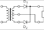
There are variations, but there are basically two types of full-wave rectifier. One requires a transformer having a secondary winding with a center tap and two diodes. The other type of full-wave device, known as a bridge rectifier, requires four diodes, but it works with any AC source. A transformer with a center-tapped winding is not needed. By way of tradeoff, there are four diodes (rather than two or one, as in the half-wave rectifier).
To obtain the same output voltage as in the bridge rectifier, the center-tapped, two-diode full-wave rectifier must have twice as many turns in the secondary winding. The power rating is not changed. The following equation is used to find the no-load output voltage of a single-phase full-wave rectifier:
VDC = 2VPEAK/π (Equation 3)
The following equation is used to find the RMS no-load output of a single-phase full-wave rectifier:
VRMS = VPEAK/√2 (Equation 4)
Three-phase rectifiers are needed in higher-power applications, where the design calls for a three-phase AC supply to be broken down into three separate two-wire DC circuits to balance the load. Like single-phase rectification, three-phase rectification may be accomplished by means of several configurations.
Rather than diodes, thyristors are often used for three-phase rectification, because the output voltage is regulated. Many generators that provide a DC output are actually three-phase AC devices. That is because three-phase AC generation is simple and efficient. The familiar 12-V automotive alternator is actually a three-phase AC generator with internal diodes that rectify the output.
A three-phase half-wave rectifier consists of one diode placed in-line for each phase. The downside in this particular circuit is that there is a heavy harmonic component at the DC output. It is present at the AC input terminals, as well, making for problems in other onsite equipment and even for outside facilities and, ultimately, for the utility. However, since the output consists of three half waves that are combined, the filtering problem is not as acute as in the single-phase half-wave rectifier. There are three pulses per AC cycle.
The harmonic component at the output is reduced in the three-phase full-wave rectifier having a center-tapped transformer. This type of rectifier has six diodes, one of which is connected to each end of each secondary winding. There are six pulses for each AC cycle.
The three-phase bridge rectifier’s input is a three-phase power source with no center tap required. The no-load DC output voltage for a three-phase full-wave diode rectifier is given by this formula:
VDC = 3√3 VPEAK/π (Equation 5)
VPEAK refers to the peak value of the line-to-neutral input voltages.
This six-pulse rectifier is an improvement over single-phase rectifiers and three-phase half-wave rectifiers regarding the amount of harmonic distortion present at both input and output terminals, but these harmonics still represent a significant amount of power.
When a high-power output is desired, a 12-pulse bridge rectifier is generally used to keep the harmonics at a low level. It consists of two six-pulse rectifiers connected in series. The advantage is that, with the AC connections made at the output of a transformer where the two bridges are 30° apart, the six-pulse harmonics are cancelled.
For elevator applications, except for the door opener and car fan, three-phase motors are the usual scenario. Almost all of them use variable-frequency drives (VFDs). These devices have front-end rectification, because DC is needed to power the inverter section. VFDs are widely used in industrial facilities, water pumping stations and wherever three-phase AC induction motors must have speed and torque control.
The rectifier section is necessary and must be in good condition if the VFD is to function optimally. The VFD works by converting the AC power supplied to the input to DC. This current is conveyed through the DC bus to the final section of the VFD, where it is changed back to AC to supply the motor. This AC is not the usual sine wave (as supplied to the premises by the utility). Instead, it is a pulse-width-modulated form of electrical energy that contains the information needed to control speed, direction and torque performance of the motor in response to automatic or manual commands.
The VFD output is created by either silicon-controlled rectifiers or insulated-gate bipolar transistors (IGBTs). Pulse-width-modulated switching performed by the IGBTs is conveyed over a carrier, the frequency of which is a proprietary value determined by the VFD manufacturer.
Returning to the rectifier section, a three-phase, full-wave diode bridge rectifier converts the three-phase AC power to DC power stored in high-capacitance electrolytic capacitors. The DC power is conveyed to the inverter section via the DC bus.
Normally, the DC bus voltage is 1.414 times the AC RMS line voltage. So, for a 480-V unit, expect to see 678 V on the DC bus. Measured with a handheld, battery-powered oscilloscope with inputs insulated from ground and from each other, the DC should be at the full value, regardless of load, and substantially free of ripple. To get a feel for this, a good, functioning unit should be viewed. If these parameters do not look right, the next step is to power down the unit and test the devices. Disconnect and lock out the supply before proceeding.
It must be emphasized that the capacitors are energy storage devices, and they can deliver a lethal shock long after the VFD has been powered down. The capacitors should not be shorted out by laying a screwdriver across the terminals or similar expedients. Instead, connect a power resistor and bleed out the voltage. Then, test for voltage using failsafe redundant procedures. Even then, there is no need to touch exposed terminals. The diodes and capacitors can be tested using specialized instruments or a good reliable multimeter, preferably with diode and capacitor check functions.
Carefully clean and remake all terminations. Sometimes, a connection will look good to an ohmmeter but in a high-voltage/high-current situation it will fail. Using conventional techniques, the rectifier section should be thoroughly tested and verified before continuing.
The output of a rectifier, as viewed in an oscilloscope display, is generally above or below the X-axis, but the amplitude fluctuates on a schedule determined by the rectifier’s AC input. This fluctuation, known as ripple, can be measured using an oscilloscope or multimeter set on the amps function.
Ripple can be tolerated in some applications, such as charging a battery where it may be beneficial, since it involves a duty cycle. But, most of the time, it is to be avoided. Ripple can introduce AC hum in audio equipment, or, elsewhere, video distortion or data corruption. Fortunately, ripple can be eliminated by incorporating carefully chosen devices in the electronic circuit after the rectifier proper. The most obvious way to do this is to place capacitors across the load. In a VFD with a three-phase rectifier, two capacitors with anodes back to back are shunted across the DC bus. There is a ground connection between the two capacitors. The capacitors store electrical energy at the high points and release it at the low points, performing the function of smoothing the DC power. Another way to look at it is that the capacitors have lower impedance to the fluctuating ripple than to the direct current, which is consequently shunted to ground.
Because of the ground connection, both DC bus lines are referenced to and float above ground potential. For this reason, a grounded bench-type oscilloscope cannot be connected to the DC bus (unless a differential probe is used). The handheld, battery-powered oscilloscope works well here.
Additional filtering is accomplished by inserting inductors, known as “chokes,” in a series configuration in each of the two DC bus lines. These are wire-wound coils with iron cores, necessary at the relatively low frequency, and they offer lower impedance to the desired direct current, while blocking AC ripple.
The VFD inverter section, not to mention the motor, works better with a DC feed free of ripple. Since inductors can become intermittently or permanently open or acquire shorted windings, these devices should be checked when ripple is detected.
Other means for ripple mitigation are also deployed. If the DC load is particularly sensitive to ripple (and, especially, if it draws very much current), designers place a voltage-regulator device at the output of the filtering capacitor(s). The regulator typically requires a minimum voltage to function, so the capacitor must be sufficiently large to prevent excessive dips. A further advantage of a voltage regulator in this configuration is that it compensates for changes in the rectifier’s AC input, as well as for variations in the connected load.
DC elevator motors are still in use in many legacy installations. When elevator renovation is ordered, there is the choice between installing a new VFD AC induction motor or rebuilding the existing DC motor. In many instances, the decision is being made to stay with the DC motor.
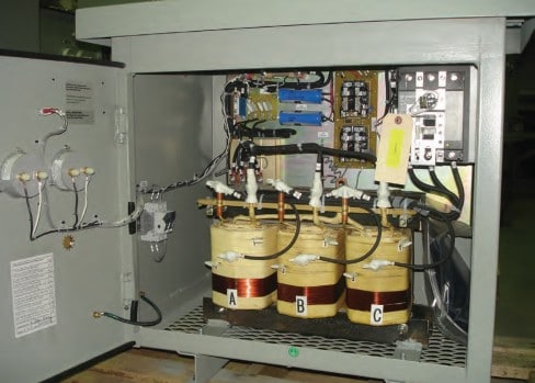
At one time, utilities provided a parallel DC distribution system so building owners could power their elevators. Some of these systems remain, but, increasingly, they are being phased out. DC power, then, must be derived from AC by means of a local rectifier. Such units are readily available as self-contained equipment in a dedicated enclosure. An older rectifier will likely have fuses, and, in case of an outage, a replacement may not be readily available, so, a new rectifier with circuit breakers is preferred.
Besides supplying DC bias for semiconductors, another application for rectifiers is the role they play in DC conversion. Since transformers are effective in changing AC voltages only, more elaborate means are required in DC voltage conversion. A resistor may be used, creating a voltage divider, to reduce a DC voltage. This circuit involves loss of energy, dissipated in the form of heat at the surface of the resistor. Moreover, rather than a single stable voltage, it is load dependent and subject to variation. True voltage conversion requires more elaborate circuitry. One method is to use an inverter to change the DC supply to AC. Then, it is changed to the desired voltage by means of a transformer, and subsequently rectified back to DC. The inverter often outputs a frequency higher than the usual utility 50 or 60 Hz so the transformer can be smaller and operate more efficiently. A frequency of over 10 kHz is often used.
Another application for rectifiers is in the detection of amplitude-modulated radio signals following radio-frequency (RF) amplification. This was originally accomplished by means of a “cat’s whisker.” Invented around 1904, this consisted of a thin wire, its pointed end resting on a galena crystal so as to make a semiconducting junction. That was a true form of rectification and extracted the audio information from the RF carrier wave. Improved performance came with the vacuum-tube diode, which had an anode and cathode heated by a glowing filament. Currently, a solid-state diode accomplishes detection.
The rectifier is the defining component in a DC arc welder, which produces an exceptionally high-quality weld. Rather than diodes, thyristors are used, providing a controllable output.
Diode rectification is simple and efficient. It has replaced electromechanical rectifiers, which were costly and consumed energy in rotary and vibratory implementations. Similarly, the electrolytic rectifier was used 100 years ago, but it is now obsolete. There were also mercury-arc valves, argon-gas electron tubes, selenium and copper-oxide rectifiers and other devices, but with the arrival of the solid-state epoch, what we are seeing is predominantly silicon-based.
Learning-Reinforcement Questions
Use the below learning-reinforcement questions to study for the Continuing Education Assessment Exam available online at www.elevatorbooks.com or on p. 137 of this issue.
♦ Why is AC preferable in electrical distribution systems?
♦ Why is DC needed in electronic equipment?
♦ What are the principal rectifier circuits?
♦ How is the voltage in a VFD DC bus calculated?
♦ When are thyristors used in a rectifier?
- Schematic of a half-wave rectifier with input and output waveforms
- Schematic of a full-wave rectifier connected to a transformer’s secondary winding with a center tap, which requires two diodes. The input and output waveforms are shown.
- Schematic of a full-wave rectifier connected to any AC source, with no center tap required, has four diodes. Input and output waveforms are shown.
Get more of Elevator World. Sign up for our free e-newsletter.

