Reginald S. Phillips’ Electric Lifts of 1939, Part Two
Jan 1, 2011
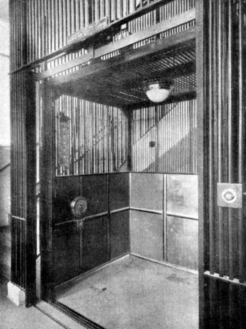
A continued look into electrical lifts and an author’s observations and difficult encounters.
Reginald S. Phillips’ Electric Lifts: A Manual on the Current Practice in the Installation, Working and Maintenance of Lifts offers unique and detailed insights into the technical and operational characteristics of pre-World War II British lifts. Part One of this series (ELEVATOR WORLD, December 2010) addressed the structure and organization of this important book and its production in the context of the 1930s lift industry and increasing governmental regulation. The first article also addressed key principles of British lift design and operation. Part Two continues this examination of Phillips’ book and focuses on the design and operation of typical lift cars, including car design, doors and gates, control systems and indicators.
Phillips observed, perhaps with slight exaggeration, that “the number of passenger car designs is unlimited” and that lift cars could “be made to almost any specification.” However, he also noted that there were a “few items of design which should be incorporated in all modern lift cars.” He stated that the interior car height “should be at least 6 ft. 6 in. and usually is about 7 ft. 0 in. or even more,” and he recommended that an alarm bell or telephone be provided “in case of breakdown or failure between floors.” Other typical features were escape hatches in the car roof or side, and provision of adequate ventilation and artificial lighting. While Phillips discussed and illustrated wooden car interiors (the most common type), he also noted, “All metal cars are becoming popular, and these too may be obtained with, or without, ornamental strips, and in almost any design and color of lacquer finish.” The increased marketing of metal car interiors may be evidence of the presence of modern design ideals that were increasingly popular in England (and elsewhere) during the 1930s.
This modernizing trend was also evident in car- and landing-door design. While, on the one hand, he noted that “the most common form of protection for lift car and landing entrances is the collapsible iron gate of the over-hung type,” Phillips also observed that “most modern high grade passenger lifts” employed “doors of various types particularly for landings.” The advantages of doors included the “elimination of draughts emanating from the well, prevention of noise being transmitted to various floors via the well openings, and improved appearance.”
The numerous door types discussed and illustrated by Phillips indicated both the variety of available options and the lack of a standard or preferred type. The door systems referenced in his book included single hinged; double hinged; single-leaf slide; two-leaf, two-speed slide; two-leaf, center-opening slide; two-leaf slide and stationary; two-leaf, slide and swing; three-leaf, two-speed slide and stationary; three-leaf, two-speed and swing; and four-leaf, two-speed and swing. Of these types, the slide-and-swing door systems are of interest, because they presented a hybrid system intended to meet different needs. According to Phillips, this door type was intended for use “on passenger lifts in which packing cases or trunks are occasionally carried. For normal passenger service the sliding door is used, but when large cases have to be handled the swing door may be opened in addition to the sliding door.”
Lift-car control systems were divided into two categories: those requiring an attendant and those “completely under the control of passengers in the car or persons on the landing.” The former systems included simple car switch control, pre-register control, department-store control and signal control. Simple car switch systems were designed for car speeds up to 400 fpm. The operator simply moved the switch to the up or down start position to initiate movement and moved the switch back to its center position to stop the car. The switch was a “dead-man” type that, if released, automatically returned to the center or stop position. In this basic control system, “good floor leveling [was] normally dependent upon the judgment of the operator.” Philips described the pre-register control system as having been “developed in America for use on lifts traveling at very high speeds, e.g. 700 ft. per minute.” Although this system relied on automatic leveling mechanisms, it also relied on the operator to stop the car at the proper destination. Its “main object” was “to supply some signal to the operator when to center the car switch so as to stop at a particular floor.” When the car entered a “stopping zone, established either by pressing a button in the car or a landing,” a signal light flashed in the car. This alerted the operator of the need to “center the car switch,” thus stopping the car.
Phillips’ description of this system also revealed the challenges faced by operators running high-speed lifts. While he noted that an in-car signal system was, of course, needed for lifts “with solid type doors,” in lifts equipped with open collapsible iron gates, accurate stopping was equally difficult:
“With open type gates it is difficult to distinguish the floor numbers when traveling at high speeds. In fact, it has been found that at a speed of 800 ft. per min. an operator cannot accurately read floor numbers even when these are painted four feet in height.”
Department-store control was similar in its operation to pre-register control, with the primary difference being the requirement (on a typical run) to stop at every floor. In this system, if the operator released the switch, the car would automatically stop at the next floor; in order to bypass floors, the operator had to hold the switch in the on position. Signal control was intended for use with banks of high-speed lifts, “employing variable voltage gearless drives, automatic leveling, and power operated doors and traveling at speeds up to about 600 ft. per minute.”
The second category of passenger-operated systems included automatic control, semiautomatic control and automatic collective control. Automatic control systems employed a single call button per floor, and a set of floor buttons and an emergency-stop button in the car. With this system, when a car was in use, all other calls to that car were ignored. Semiautomatic control was only used in low-rise settings. The car was equipped with separate up, down and stop buttons. When the up or down button was pushed, the car would begin to move and only stop when the stop button was pushed. In some variations of this scheme, the operator was required to continually press the up or down button in order to make the car move; if the button was released, the car stopped.
The most sophisticated system was automatic collective control, which Phillips said had been “developed during recent years with the object of providing a fully automatic push button system.” Thus, “every button pressed, whether the car is stationary or in motion, registers a call,” and “up and down calls are answered during the up and down journeys respectively, in the order in which the floors are reached.” Phillips also noted that this system allowed cars to be “parked” at preselected floors – a feature that could be “desirable when important persons are located on a certain floor or when heavy traffic is expected.”
Phillips also addressed car and landing indicators. Many cars were equipped with “target indicators,” which employed “electromagnetically operated targets made visible” when landing call buttons were pressed. The “targets” would indicate the prospective passenger’s location and desired direction of travel. The complete system consisted of “one magnet-operated target for each floor served, a controlling relay, and a buzzer.” When a landing button was pushed, a magnet moved a “corresponding target into view, thereby registering the signal in the car.” As the target moved into view, the buzzer gave “an audible signal” that a call had been “made and registered.” After the operator answered the call, he or she would push a reset button that energized a second magnet, which moved the target “out of sight.” A variation of this system employed one bull’s-eye light and one canceling button per floor. The appropriate bull’s eye would glow (and the buzzer would sound) when a call was registered in the car, and the operator would push the cancel button after the call had been answered.
A more sophisticated system that eliminated the need for reset buttons was also available. In this system, the bull’s-eye lights were automatically “extinguished” when the car reached the landing:
“The relay and lamp circuits are disconnected by the opening of contacts on the landing gates, and the calls therefore remain registered until the corresponding landing gates are opened.”
Of course, in addition to car indicators, there were also landing indicators, which, according to Phillips, were necessary in order “to avoid impatience on the part of waiting passengers.” The various types included bull’s-eye lights that glowed when a car was moving. The typical colors employed were apparently red for down travel and white for up. Directional indicators composed of either arrows or illuminated signs were also used. Their operation was described as follows: “after the lift has passed each floor, the corresponding lamp is extinguished until the lift is again approaching.” Position indicators were popular, and Phillips observed, “The tendency on most modern lifts is to indicate the position of the car in the well, either with, or without, a separate direction indicator.” The most intriguing type illustrated was one that utilized an “illuminated miniature car and well” with a horizontal line in the indicator window that indicated “the position of the waiting passenger’s floor.”
A continued survey of Phillips’ book would permit investigations into motors, safeties, brakes, counterweights, guides and other features. However, this two-part article has hopefully served as a useful introduction to this important book and offered a glimpse into the world of 1930s British lifts. In fact, Phillips’ books provide an overview of this industry from the 1930s through the 1970s. (Phillips went on to write five additional editions of his book, which were published in 1947, 1951, 1958, 1966 and 1973, respectively.) During much of this period, the author worked for the Post Office Engineering Department, initially (in the 1930s) as a power engineer, rising to the position of staff engineer by the late 1950s and retiring in the early 1970s. During this period, he was also a member of the Institution of Electrical Engineers and made a fellow of the institution in the late 1960s or early 1970s. Regrettably, this is all that is known about Phillips. If any EW readers have additional biographical information they wish to share about him, it would be very much appreciated.
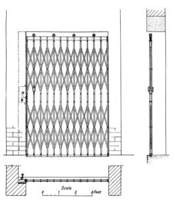
William Wadsworth & Sons, Over-Hung Collapsible Iron Gate 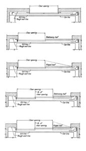
Lift Door Systems: (top to bottom) two-leaf, center-opening slide; two-leaf slide and stationary; two-leaf, slide and swing; three-leaf, two-speed slide and stationary; and three-leaf, two-speed and swing 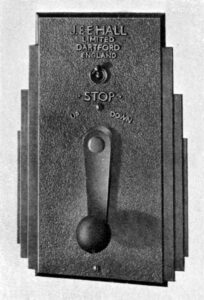
J. & E. Hall, Single Speed Car Switch 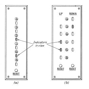
Target indicators: (a) single indicators and (b) up and down indicators. 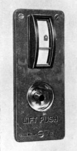
Marryat & Scott,
Call Push and
Car Position Indicator
Get more of Elevator World. Sign up for our free e-newsletter.


