
A comprehensive look
The subject of remote elevator monitoring requires careful consideration of all consequences associated with the use of this technology. Ensuring that the technology enhances the safety of the riding public should be the minimum standard when deciding to utilize elevator monitoring technology. It is important to ensure that utilizing remote monitoring does not lead to reduced maintenance visits, which could result in the hazardous accumulation of dirt and debris in the equipment. This article will look at the history of controller development leading to the need and availability of remote monitoring, methodologies for determining what should be monitored and how documenting equipment malfunctions is critically necessary and required by the A17.1/B44 Safety Code for Elevators, Escalators and Moving Walks (Code).
Historically, older elevator logic controllers were based on relay logic before the implementation of computer logic or microprocessor controllers. Depending on the complexity of the unit, there were dozens to hundreds of relays in a control system supported by components such as vacuum tubes, power supplies, diodes, metal oxide varistors, capacitors and other components. When a relay logic-based controller component, system, subsystem or function malfunctioned, there was generally physical evidence of the cause of the failure: a relay coil failing to pick when energized, a welded relay contact, a broken shunt, a shorted diode, an open resistor, a blown capacitor or a myriad of other issues visible to the experienced mechanic. With proper training and experience, the nature of the malfunction could be identified down to a particular circuit and then to the faulty component.
Understanding electrical theory was essential, especially knowing where electrons were supposed to go and where they were not. Armed with a voltmeter, an ammeter and Ohm’s Law, troubleshooting was a skill necessary to resolve many problems. Knowledge of motor theory, particularly understanding magnetic flux and its failure implications, also guided the elevator mechanic to a resolution. This was the art of “elevator troubleshooting” and a measure of a mechanic’s abilities.
Complex relay logic circuits have an order of picking and dropping relays, but a relay coil can weaken and “half-pick” due to age, dirt, debris accumulation or internal coil shorting. A malfunction might occur depending on the cleanliness of the controller and the humidity and temperature of the machine room. The relay may fully pick most of the time but occasionally only half-pick, causing a contact to fail intermittently. Knowledge and experience would lead to corrective action, and an elevator was not returned to service until the root cause of the problem was fully identified and corrected. In some cases, the corrective action might involve replacing all suspect relay coils and monitoring to see if the problem recurred. Timers, reliant on Resistor/Capacitor (R/C) relationships, could malfunction, shortening or delaying critical timing and causing malfunctions. Transient voltages caused by improper removal of magnetic blowouts on high-power relays or lightning could create destructive high voltages, breaking down wire insulation and leading to malfunctions. This list is endless, and the examples are only provided here for some context.
Over time, many controller components were replaced by solid-state devices using Diode-Transistor Logic (DTL) and Transistor-Transistor Logic (TTL) technologies. The transition to these technologies required elevator mechanics to understand solid-state logic and Positive/Negative (P/N) junctions, and based on that understanding, troubleshoot failures in solid-state components. Where a device should switch states based on P/N junction voltage differences, understanding how these operated was essential to determine why a logic component malfunctioned. Many times, these issues were resolved by simply replacing a Printed Circuit (PC) Board that had test points for measuring voltages that were out of tolerance. However, the logic was still accessible to the mechanic with a Digital Volt Meter (DVM) and experience.
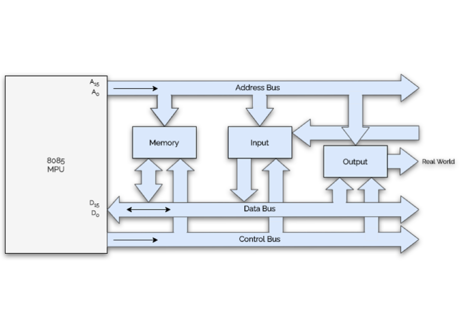
Next came microprocessor controllers, which allowed the placement of all logic into arrays of miniaturized transistors on solid-state chips so small they can’t be seen. The software and microprocessor registers the Address, Data and Control buses that transfer bits of information, the Read-Only Memory (ROM) and Random Access Memory (RAM) working in conjunction to command the elevator to start and stop with Input/Output (I/O) modules. I/O is where high voltage signals are converted to low voltage signals and vice versa. For instance, a 48-V signal would input to an attenuator that converts the signal to 5 V, which then became a “high” signal transferred onto a data bus, sent to the microprocessor, informing the system of a demand from an input. When the 48 V goes to 0 V, the data bit reverts to a zero of “low” signal, hence a binary system of ones and zeros using voltage to determine an input “state.” The software would then evaluate this and provide an output signal that is amplified to light a pushbutton when a call is registered, for example, setting in motion the logic for the elevator to respond and move. While this may seem complex, it is not difficult with the correct logic and controls and understanding logic. What was once done with vacuum tubes and relay contacts is now achieved with transistors, a microprocessor, software and the necessary electronics to make the microprocessor operate.
In the case of computer logic controllers, relay half-picking problems were replaced by unseen voltage fluctuations in the logic voltage, unseen delays in serial communication timing or unseen damaging transient voltages partially destroying silicon substrate P/N junctions of solid-state components. These intermittent malfunctions are no longer visible, and it is not uncommon to simply replace the solid-state PC board to help isolate the problem to external components or issues within the board itself. Light Emitting Diodes (LEDs) are used as indicators of the status of I/O signals, but even LEDs have a limited lifespan. In a computer logic controller, there is no physical visibility to observe the software logic in the field. When I/O solid-state components or any solid-state components malfunction, causing an illogical condition, another computer is needed to see all the I/O signals the manufacturer chooses to make accessible in real-time to determine if the signals are progressing through the controller correctly. Fault codes were ultimately provided on all microprocessor controllers to give trained mechanics some visibility into the cause of malfunctions. This transition from observing relay logic failures to interpreting fault codes is the most significant change in troubleshooting controller malfunctions.
With the introduction of the internet and cloud connectivity, fault codes can be transmitted anywhere for remote troubleshooting, not just for the local mechanic standing near the unit with a laptop and the correct interfacing software. RC timers have been replaced with digital flip-flop timers that accurately count units of time and are easily adjusted with the correct parameter settings, even remotely. Interconnected circuits using relay contacts have been replaced with subsystems that communicate their interconnected demands via serial communication systems, utilizing RS 232, RS 485 and CAN Bus serial communication protocols to ensure reliable data transmission. All components can be verified — that the safety string is intact, the door locks are closed, the motor is ready and safe to move and the doors can open and close by merely converting their data into a “bit,” which is ultimately a high or low voltage signal converted to a serial string of data in a “byte” and can be exported to any Uniform Resource Locator (URL) in the world. Safely setting the elevator into motion requires coordination among all components, systems, subsystems and functions, ensuring they operate in the correct order, which is done at the local controller. The internet allows a gateway beyond the local controller into data banks managed by designers and engineers.
Ensuring that the technology enhances the safety of the riding public should be the minimum standard when deciding to utilize elevator monitoring technology.
Remote elevator monitoring was introduced in the 1990s to provide information to the mechanic, enabling them to see if the computer logic progression was functioning as expected, identify malfunctioning components and devices and, importantly, see hazardous operation of the elevator system and turn the elevator off. Troubleshooting involves correctly identifying a malfunction, ideally down to a specific component or function, by providing the information necessary to repair, replace or adjust a component with assurance that the problem is fully identified and that corrective actions address the root cause of the malfunction.
Providing information to the mechanic was not the only purpose. with remote elevator monitoring, component time-life, mean time between failures, number of runs the elevator makes, number of door cycles recorded and many other data points were recorded and documented to assist designers in product design, R&D and evaluation of the life expectancy. It has the potential to allow a prediction of a failure of a component, for example, if a roller on a roller guide has a design specification of 20 million revolutions before failure, knowing how many revolutions it has completed could be used to replace it at 19,900,000 revolutions before it fails. This is the promise of predictive maintenance.
Controller designers have all the information, and fault codes are designed to guide the mechanic to the root causes. However, the complexities of any system can lead to misinterpretation of root causes because the system, the microprocessor and its required components are now new potential failure points. The accuracy of the information relies on the system itself operating correctly. If there is a software bug, the data may be inaccurate if the system is subjected to high transient voltage causing PN junctions to switch on and off incorrectly, or if serial communication is delayed, attempts to identify all malfunctioning conditions to find the root cause may be skewed. These issues ideally correct themselves over time as designers gain more experience with each control system. New fault codes are developed to identify newly discovered malfunctions, aiding in finding the root causes. But there are limitations to even adding more fault identification since the information is processed by components that may themselves be malfunctioning.
The throughput of information is limited by the microprocessor’s speed, and any additional burden on the microprocessor could necessitate a more expensive, faster microprocessor. Software takes time to run, and adding more software increases the time required to process tasks, taking away from the task of running the elevator. This limitation on microprocessor time is a constraint on fault code processing, so designers must carefully consider which fault codes are built into the system and available to the mechanic. Earlier generations of microprocessor controllers operated at slower speeds (megahertz clock speeds) and could only resolve 8 bits of information. Today’s controllers resolve up to 64 bits of information at gigahertz speeds — seemingly limitless, but still constrained.
All of this is also in light of Code requirements, which attempt to ensure that Electrical Protective Devices (EPDs) in Critical Operating Circuits (COCs) function correctly and provide protection against software failures. The Code requires monitoring welded contacts — typically by using Force-Guided (FG) relays and redundant hardware logic arrays to ensure that COC input information is accurate. These protections are designed to keep the system safe, preventing the elevator from running with the doors open, for example, or from reverting to automatic operation while on inspection, thereby protecting both the mechanic and the general public.
The Code has also required documentation and record-keeping for decades. Documenting the corrective actions has been required when taking a call, for example, documenting what was done when correcting a malfunctioning elevator. For instance, a time ticket in the 1980s would document replacing the “C” relay coil when it failed. A record in the machine room would notify the next mechanic that a previous call included that corrective action. Today, the fault code must also be documented for the same reason, along with the corrective action taken. This is not being done with any regularity and is a Code violation. Rarely is there a time ticket that documents the fault code, leaving the next mechanic without the valuable information needed to fix the next malfunction. If the corrective actions are not documented, the next mechanic starts from scratch, and the prior information is lost. This violates the Code and the spirit of troubleshooting controller malfunctions.
The required description of the problem must be documented on the time ticket, which would include the fault codes. The required description of the corrective action taken to be documented, including a precise description, for example, “replaced PMI 12 I/O module” or “replaced the door board and reset the door parameters.” Remote monitoring records and transmits these fault codes but, in my experience, are never added to documented descriptions, either for proprietary reasons or because companies do not believe they are required by Code. This is the antithesis of what the Code requires, and these reports should be kept for later reference to ensure that the root causes of malfunctions are available for later evaluation by more than just the controller designing company.
Many companies use the transmission of this data to identify oncoming or ongoing malfunctions and can send this data directly to a mechanic in the field. Some companies tout that they can know the elevator is malfunctioning before the owner is aware of a problem. This is nuanced and generally true, provided the information is thorough and the mechanic is properly trained and has the manuals necessary to decode the fault codes. Some fault codes are simple; for example, the final limit is open or the doors didn’t close in the expected time. Many are too broad; for example, a serial communication was delayed or unexpected, which gives some indication of a problem but is not specific enough to identify the root cause, such as why the communication was delayed. Was it a delay on a bus, a register, a communication chip in the controller or down the hoistway at a pushbutton? Mechanic training and experience are essential to identify the problem thoroughly and efficiently correct it.
For years, remote elevator monitoring has also been used as a justification to reduce preventive maintenance visits. The prevailing reasons for reduced maintenance visits are the benefits of knowing if malfunctions are critical and must be corrected immediately, which also, by definition, means the failure is the trigger to visit the elevator—prevention of failure is no longer the emphasis. Some documented faults are non-critical; they result from a delivery person using a box to hold a door while delivering packages. This is not a critical malfunction, and eventually, the box is removed, and the elevator is returned to service. The lack of persistence of a fault code leads to the conclusion that the fault was not of the elevator but of external user behavior. Other faults may persist; a communication error that occurs twice a month may be critical or non-critical. What causes a callback becomes a subjective choice of the maintenance company to determine if the fault is critical or not. Since the entire system is serial communication dependent, any communication fault should be considered a critical fault, but they are not always, in my experience.
Preventive maintenance includes housekeeping. Regardless of the technology of the controller, dirt and debris accumulate on the elevator equipment and must be cleaned to ensure malfunctions don’t occur. For example, the pit of an elevator is typically a dirty environment. If debris accumulates in a compensation sheave switch, the switch may fail, causing a sudden stop while the elevator is running at rated speed. Had the pit undergone the required preventive maintenance task of being cleaned, this would not have occurred. No technology can overcome the need for housekeeping, yet housekeeping is the first task that is abandoned by maintenance companies. Knowing the compensation sheave switch failed and has its own fault code does not prevent the failure; it allowed the failure to occur, causing a hazardous event. This is the antithesis of preventive maintenance.
Remote monitoring has the advantage of seeing into the invisible control system and is a tool for troubleshooting, but it cannot replace preventive maintenance. Used wisely and in conjunction with regular preventive maintenance site visits, it is an extremely valuable tool. Unfortunately, remote monitoring is being used to justify what were once monthly visits to quarterly or even twice-yearly site visits, unwisely. The Code addresses the metrics to determine the intervals between preventive maintenance visits, and when ignored, hazards are allowed to creep into operation, with devastating harm in some cases.
The subject of remote elevator monitoring requires careful consideration of all consequences associated with the use of this technology. Ensuring that the technology enhances the safety of the riding public should be the minimum standard when deciding to utilize elevator monitoring technology. It is important to ensure that utilizing remote monitoring does not lead to reduced maintenance visits, which will result in the hazardous accumulation of dirt and debris in the equipment. Documenting equipment malfunctions is critically necessary and required by the Code.

Get more of Elevator World. Sign up for our free e-newsletter.
![]()


![]()