Reopening Devices Required by ASME A17.1-2019/CSA B44-19 Section 2.13.5
Aug 1, 2024

Why CEDES chose not to design a 3D light curtain for doors.
Value: 1 contact hour (0.1 CEU)
This article is approved for Continuing Education by NAEC for CET®, CAT® and QEI credit and by NAESA International for QEI.
EW Continuing Education is currently approved in the following states: AL, AR, CO, FL, GA, IL, IN, KY, MD, MO, MS, MT, NJ, OK, PA, UT, VA, VT, WA, WI and WV | Canadian Province of BC & ON. Please check for specific course verification of approval at Elevator Books.
Learning Objectives
After reading this article, you should have learned about:
- What the 2019 version of the Code requires for reopening door devices in horizontal door applications.
- The number of moving lines(s) of detection based on the type of door opening and how the moving line(s) of detection is defined.
- How variations in the gap between the doors, the landing door thickness and the detection means location affect device performance.
- Why the 225-mm (9-in.) distance is so important.
- Why CEDES decided to go with infrared Time-of-Flight technology.
by James O’Laughlin
The American Society of Mechanical Engineers (ASME), an American National Standards Institute (ANSI)-approved standards developer, defined new, more prescriptive door protection requirements in the 2019 Elevator Safety Code[1] (“Code”) to help mitigate the hazards associated with the landing doors in an elevator. The requirements were updated for reopening devices used in horizontal door applications due, in part, to the number of injuries that are still caused by people being struck by elevator doors. Based on reviews of the U.S. Consumer Products Safety Commission (CPSC) National Electronic Injury Surveillance System (NEISS) database, elevator passenger injuries documented across all age groups were significant during the periods evaluated.[2][3][4] Data from subsequent years affirm the conclusions drawn from the data sets remain valid.
Elevator Safety Code Requirements
This 2019 version of the Code requires reopening devices used in horizontal door applications must fulfill:
- A means of detecting a person or object in the path of the elevator cab door(s); and
- A means of detecting a person or object approaching the elevator cab entrance.
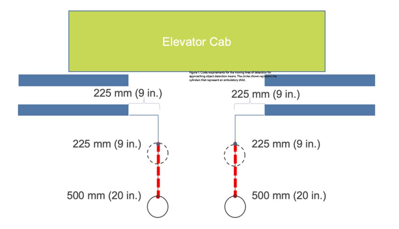
The requirements in Section 2.13.5.3 of the Code provide prescriptive detail on what the detection field must detect for persons or objects approaching the elevator cab entrance. The requirements in this section were new in the 2019 Code. At a minimum, persons or objects must be detected at some point along a defined moving line(s) of detection (Figure 1). This moving line(s) of detection is defined relative to the landing side of the leading edge of the landing door (the hazard). Hence, there are two moving lines of detection in center-opening applications and one moving line of detection for side-opening applications.
As the door(s) is closing, the moving line(s) of detection move(s) with the landing door(s) until it (they) have reached a position 18 in. (450 mm) from full close, at which point the approaching object detection means can be rendered inoperative. This point is where the two moving lines of detection in a center-opening elevator application come together. Prior to the render inoperative position, a person or object on the moving line(s) must generate a door reopen signal. Figure 1 provides a visual representation of what the Code requires in center-opening applications.
Once the Code requirements became clear, CEDES investigated several solutions that would fulfill the Code, including a solution that incorporates approaching object detection (3D) into the same housing as the object between the doors detection (2D). This solution is often referred to as a 3D light curtain. After careful design review, it was determined that a light curtain was not viable for a significant number of elevator applications. To better understand why this is the case, this white paper walks you through the decision-making criteria that led to this conclusion and, thus, CEDES’ pursuit of a transom-mounted detection means to fulfill the approaching objects detection requirements defined in the Code.
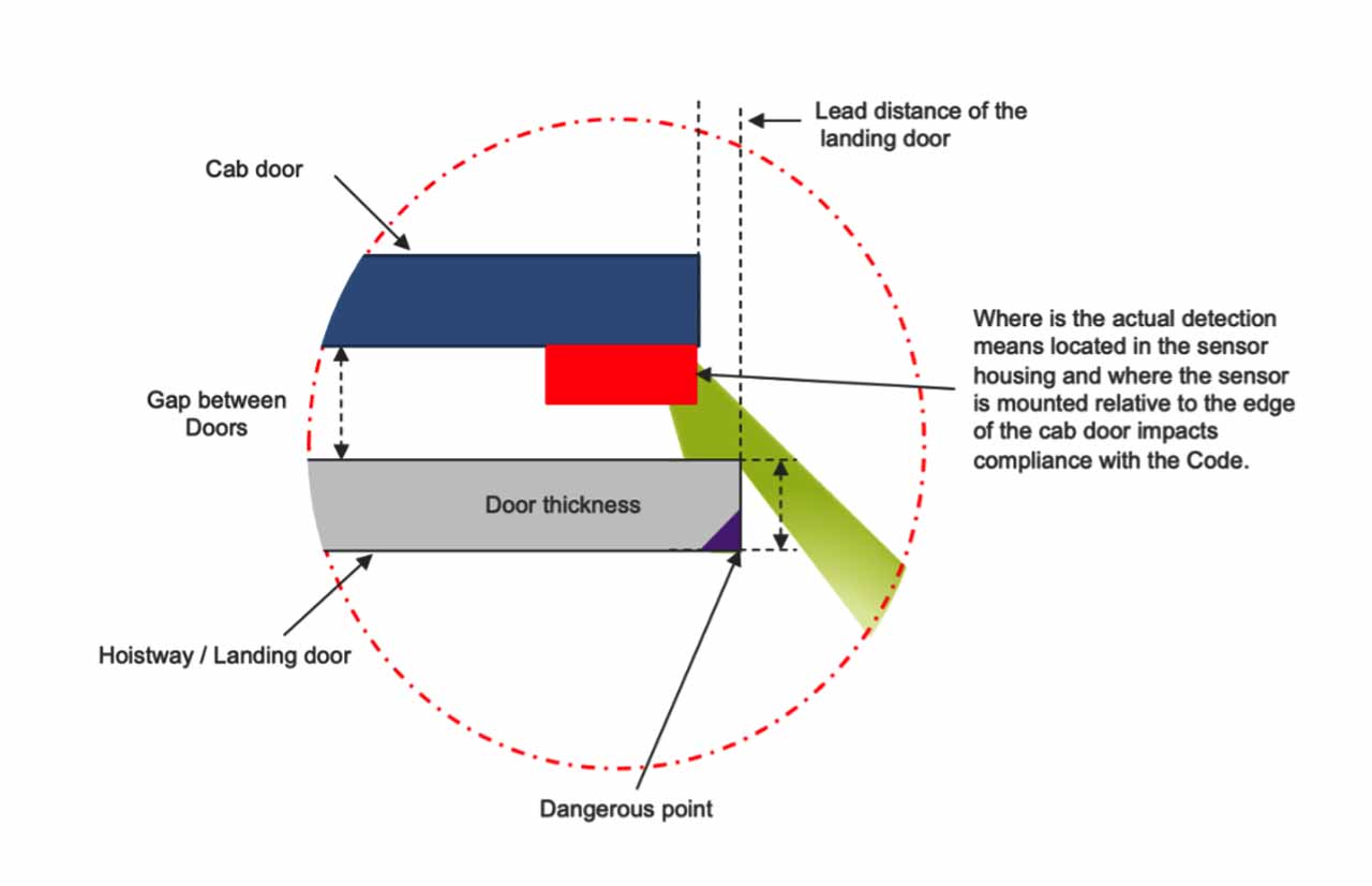
As we began our investigation into a 3D light curtain to fulfill the Code, we put together a diagram similar to what is shown in Figure 2.
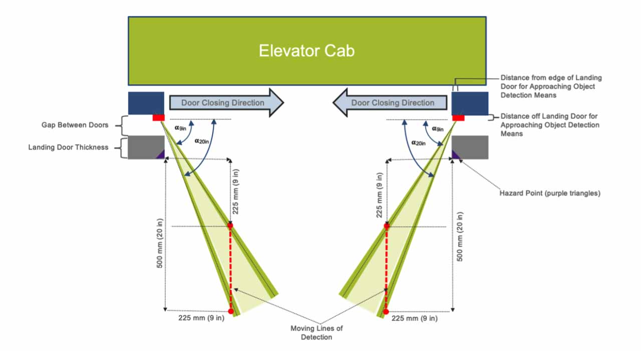
The hazard recognized by the Code is the leading edge of the landing side of the landing door(s) (reference the purple triangles in Figure 2). With the light curtain mounted on the cab door(s), and not on the landing door(s), care must be taken to consider additional factors that affect device performance, including:
- The gap between the doors [Gap CD-LD]
- The thickness of the landing door(s) [LDT],
- The detection means location [DML] relative to the car door, and …
Based on our Voice of the Customer discussions, minimum and maximum values were compiled for these parameters. Basic trigonometry was then used to determine the minimum (∞225 mm) and maximum (∞500 mm) angles that would need to be considered in order to fulfill Code requirements based on the formula:
For example, using the following values:
- Gap CD-LD: 50.8 mm (2 in.),
- LDT: 25.4 mm (1 in.), and
- DML: 15.0 mm (0.59 in.) off the car door,
Leads to:
Using only these parameters, the angle necessary to fulfill the Code using a 3D light curtain would need to be between 51.7° for the 225-mm (9-in.) point and 68.1° for the 500-mm (20-in.) point.
However, to make things more challenging, the parameters used are not fixed and do vary from application to application. Nominal values, based on Voice of Customer, revealed that the values ranged:
The design could not be based on a single set of parameters, and it was clear that a larger range of values was required. By increasing the angle (∞) used, up to a point, more applications could fulfill the Code. However, the larger the angle, the more likely other issues could arise. In particular, if the landing door leads the cab door during the closing process, it prevents the 3D from working properly. This scenario is shown in Figure 3.
This poses significant challenges, since OEM customers indicated that the landing door could lead the car door by up to 25.4 mm (1 in.) for new installations. Furthermore, we have seen several modernization applications where the landing door led the cab door by even greater distances. Using wider angles of divergence/acceptance might mitigate some risk, but the inability to see around the landing door(s) in many applications could not be mitigated.
Alternatively, we could choose to look across to the other side of the opening rather than outward from the same side of the opening (see Figure 4). This would help mitigate a leading landing door and even looks plausible to fulfill the Code requirements for approaching object detection. The details, however, prove otherwise.
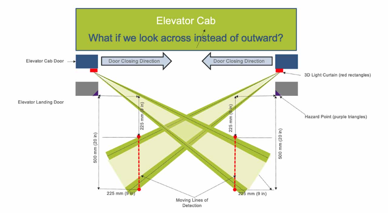
Figure 4 shows that when the doors are in their fully open position, the approaching object detection means could be designed to detect along the moving lines of detection defined by Code. However, the approaching object detection means does not move relative to the moving line of detection associated with the opposing door. Before the approaching object detection means could be rendered inoperative according to the Code, it no longer detects the moving line(s) of detection required by the Code. This is shown in Figure 5.
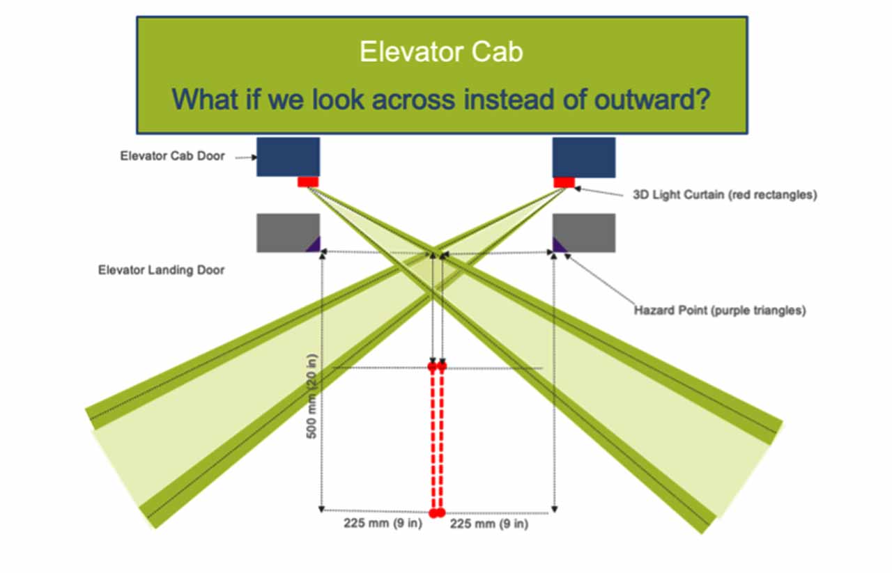
In this scenario, the sensor does not, and indeed cannot, meet the Code requirements. We can use the same parameters from our earlier calculation to determine the details. Namely,
- Gap CD-LD: 50.8 mm (2 in.),
- LDT: 25.4 mm (1 in.), and
- DML: 15.0 mm (0.59 in.) off the car door
The location of the 225-mm (9-in.) point on the moving line of detection is perpendicular to the landing side of the landing door and serves as the minimum detection distance defined by the Code. In the following calculation, we will define this point as the Opposite distance.
Opposite = Gap CD-LD + LDT – DML
= 225 mm (9 in.) + 50.8 mm (2 in.)
+ 25.4 mm (1 in.) – 15 mm (0.59 in.)
= 286.2 mm (11.27 in.)
The distance parallel to the landing door can be defined as the Adjacent distance, and s calculated based on:
Tan (θ) = Opposite / Adjacent.
If we use an emitting/receiving angle of 40° for the value of q, the Adjacent Distance is calculated as:
Adjacent = Opposite / Tan (40°)
= 286.2 mm (11.27 in.) / 0.839
= 341 mm (13.42 in.)
For a center-opening application, the Adjacent value is doubled since it applies to both doors and both moving lines of detection. The Code allows the approaching object detection means to be rendered inoperative at 450 mm (18 in.) from the fully closed position. For Adjacent distance multiplied by two, the distance where the approaching object detection means becomes ineffective is 682 mm (26.8 in.), a value that is fully incompatible with the render inoperative position allowed by the Code.
We must also consider that this value is based on a single, somewhat favorable, scenario. If the gap between the doors increases or the door thickness increases or the detection means location decreases, the Adjacent distance increases accordingly.
As it turns out, the point just before the approaching object detection means can be rendered inoperative as allowed by the Code — the angle required for looking across to the other side of the opening is exactly the same as the angle required for looking outward from the same side of the opening since application geometry for looking across to the other side of the opening is identical just prior to rendering inoperative.
Why the 225-mm (9-in.) Distance Is So Important
The location of the moving lines of detection defined in the Code was based on allowing for sufficient time to have the doors stop and reverse once a person or object has been detected. If this occurs too close to the doors or if there are sufficient time delays, e.g., as shown in Figure 5, it can lead to a person being struck by the doors. This scenario is particularly viable since persons/objects often approach the elevator as the doors are closing.
Other Performance Requirements
The Code also defines detection capability based on the technology used. For the 2019 Code, the properties were defined based on the use of infrared technology in the detection means for both approaching objects and objects located in the door path. The 2022 Code changed this language to “and detectable properties of a human applicable for the technology used.” Regardless of which version, it is reasonable to expect that the detection means is capable of detecting persons or objects, regardless of color or type of clothing.
In order to fulfill this requirement using infrared technology, CEDES determined that the use of distance-measuring technology (e.g., Time-of-Flight [TOF]) is necessary to minimize measurement variations caused by different reflectivity properties (e.g., color of clothing). Without distance measurement, the detection of approaching objects on the moving line(s) of detection cannot be effective.
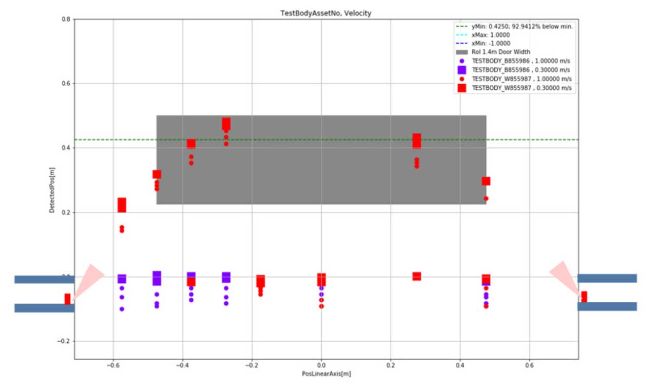
Test results of an infrared photoelectric device (a 3D light curtain) are shown in Figure 6. Currently, the manufacturer of this device does not have a published third-party test certificate but claims compliance to the 2019 Code requirements just the same.
The cylindrical objects used in the testing had reflectivity properties defined by the 2019 Code. These test cylinders were also used for the testing of the CEDES CabSafe™ system, which has been third-party certified as Code compliant. The results for the competitive 3D light curtain are shown in Figure 6. Note that the black test body (purple boxes and dots) was not detected by this system as required by the Code [see Section 2.13.5.3 (a)].
The red circles shown in Figure 6 refer to measurements associated with a glossy white test object (minimum 90% IR reflectance), and the purple circles are measurements associated with a black test object (maximum 5% IR reflectance) defined by Code. The circles indicate first detection of the test object as it approaches the elevator entrance. Note the significant numbers of first detection that occur at the detection means for objects between the doors (i.e., there was no detection by the approaching object detection means).
Based on these findings, CEDES determined that traditional infrared transmitters and receivers could not reliably fulfill Code requirements on their own unless, e.g., infrared TOF technology, was used.
Summary and Conclusions
Based on the application requirements, both from the Code’s and our customers’ perspectives, CEDES determined that incorporating the approaching object detection means into the same housing as the objects in the door path detection means (i.e., developing a 3D light curtain) would not solve a significant number of elevator installations. The following points weighed heavily in this discussion:
- Figure 1 shows that the hazard is defined as the leading edge of the landing side of the landing door. The angles required to fulfill the approaching object detection means defined by the Code must account for several uncontrolled parameters, including:
- the gap between the doors,
- the landing door thickness,
- the location of the detection means relative to the above parameters.
- Figures 2, 4 and 5, and the associated calculations presented in this paper show:
- The angle required needs to be greater than 50° outward relative from the plane of the doors to fulfill a minimum number of applications.
- The angle required needs to be greater than 60° outward relative from the plane of the doors to encompass a significant number of applications, but not all, due to larger gaps between the doors.
- An approaching object detection elevator cab door door-mounted sensor (i.e., 3D light curtain) that utilizes transmission/receive angles of less than 50° cannot fulfill Code requirements — a majority, if any at all, elevator applications.
- As shown in Figure 3, when the landing doors lead the elevator car doors, larger transmission/receive angles may not allow an approaching object detection means in fulfilling Code requirements, i.e., the detection means cannot see past the landing doors.
- As shown in Figure 6, avoiding variations in effective distances caused by, e.g., color of clothing, requires the use of distance measurement technology. A person approaching an elevator entrance in a black shirt and blue jeans (low IR reflectance) should be just as important as a person approaching the entrance wearing a white shirt and khakis (higher IR reflectance).
- Other historical performance issues associated with direct sunlight also affected this decision.
Based on these points, CEDES chose to develop its Infrared (IR) TOF transom-mounted CabSafe system as a solution for approaching object detection defined in Code.
CEDES insisted on third-party certification of the CabSafe System to provide customers the confidence that the CabSafe system, indeed, fulfills the 2019 Code requirements. Many customers also tested the CabSafe system on their own and validated the test results, coming to the same conclusions.
Liftinstituut reviewed the CabSafe design, documentation and test results. Upon completion of the investigation, it certified that CEDES CabSafe, indeed, fulfills the 2019 and 2022 Elevator Safety Code requirements defined in Section 2.13.5 Reopening Devices for Horizontal Elevator Doors when installed according to the CabSafe installation and operation instructions. The Liftinstituut certificate, along with overview, technical support, operating instructions and other information, are available at cedes.com/en/products/cabsafe/.
Learning-Reinforcement Questions
Use the below learning-reinforcement questions to study for the Continuing Education Assessment Exam available online at Elevator Books or on p. 127 of this issue.
- Why is the 225-mm (9-in.) distance so important?
- Why did CECES determine that traditional infrared transmitters and receivers could not reliably fulfill Code requirements on their own unless, e.g., infrared TOF technology, was used?
- What do the 2019 and the 2022 Code require for reopening door devices in horizontal door applications?
- How many moving lines(s) of detection are there for each type of door opening and how are these defined?
- How do the variations in the gap between the doors, landing door thickness and detection means location affect device performance?
References
[1] ASME International (ASME). ASME A17.1-2019 / CSA B44:19 Safety Code for Elevators and Escalators – An American National Standard (ANSI). ASME International: New York, New York. December 31, 2019. Pages 58-60, 502-505.
[2] Joseph O’Neil, MD, MPH, Gregory K. Steele, DrPH, MPH, Carrie Huisingh, MPH, and Gary A. Smith, MD, DrPH, Department of Public Health, Indiana University School of Medicine. Elevator-Related Injuries to Children in the United States, 1990 Through 2004. Clinical Pediatrics. September 2007. Sage Publications. Pages 619-625. journals.sagepub.com/doi/abs/10.1177/0009922807300232.
[3] Deborah E. Morrison-Ibrahim, Department of Public Health, Indiana University School of Medicine. Retrospective Analysis of Elevator Related Injuries in Ages 20-64, 1990-2002. Unpublished between 2010-2012. Study obtained from Dr. Gregory Steele on March 4, 2013. Pages 1-35.
[4] Gregory K. Steele, DrPH, MPH, Joseph O’Neil, MD, MPH, Carrie Huisingh, MPH, and Gary A. Smith, MD, DrPH. Department of Public Health, Indiana University School of Medicine. Elevator-Related Injuries to Older Adults in the United States, 1990 to 2006. The Journal of TRAUMA® Injury, Infection, and Critical Care. January 2010. Lippincott, Williams & Wilkins. Pages 188-192. journals.lww.com/jtrauma/Abstract/2010/01000/ Elevator_Related_Injuries_to_Older_Adults_in_the.32.aspx.
Get more of Elevator World. Sign up for our free e-newsletter.


