Reverse Bending and Its Effects on Lift Ropes
Jul 17, 2023
by Serdar Tavaslıoğlu
In the assembly training videos I published, there were questions about the sheaves that cause reverse bending, which was mentioned in the machine placement section. It was asked what the points are to be considered in the case of using sheaves causing the reverse bending in lift ropes, and on what basis it is demanded that the distance between sheaves be 60 times the diameter of the rope. The situation mentioned in the training video was mainly related to the fixed sheaves located in front of or behind the traction sheave, with the direction of rotation opposite to the traction sheave. If these sheaves are not installed properly, they both shorten the life of the rope and more importantly, they affect the traction ability of the lift in a way that puts the use of lift at risk. Rope wire breakage and rope clamping (rope pinching and non-slipping between the reverse bending sheaves) are among the important issues in lifts. These issues should be examined in turn.
Bending on Lift Suspension Cables
As it is known, the suspension ropes in lifts are among the main components of the lift in terms of operation and safety. Ropes are classified, manufactured, maintaine, and tested subject to various standards. And they are removed from operation in case of negative conditions specified in the standards. There are quite detailed studies and examinations on ropes which are one of the main components of various products alongside the lifts.
General properties of steel wire ropes are defined in the TS EN 10264 standard series. For sampling and test procedures, “EN 10264-1 Steel wire and wire products – Steel wire for ropes – Part 1: General requirements” standard is used. Classification and requirements of ropes according to the uses are given in the EN 12385 series. Among these, “EN 12385-5 Steel wire ropes – Safety – Part 5: Stranded ropes for lifts” defines the ropes to be used in lifts while the EN 81-20/50 standard is based on it for the rope properties used in lifts. The rules for the examination and discard of ropes are explained in the “ISO 4309 Cranes- Wire Ropes-Code of practice for examination and discard” standard. For the lift practices, “ISO 4344 Steel wire ropes for lifts — Minimum requirements” standard can also be used. Apart from these, there are numerous codes of practice and standards regarding the ropes.
Various articles have been published on the uses, practices and maintenance of the ropes. It is also possible to benefit from the publications of our esteemed professors on these subjects. Some of these publications include.
- Transmission Technologies Congress 2003 Proceedings, “Asansör Halatları ve Mekanik Yapıları” and “Asansör Tesislerinde Bakım ve Yöntemleri” C.Erdem İmrak, Recep Demirsöz
- “İletim Teknolojisinde Kullanılan Tel Halatların Bakımları” Adalet Zeren, Hülya Yetiştiren
- Lift Symposium 2006 Proceedings, “Asansörlerde Kullanılan Çelik Tel Halatlar, Seçim ve Bakım Yöntemleri” Serpil Kurt, C. Oktay Azeloğlu
- II. Maintenance Technologies Congress and Exhibition Proceedings 2005 “Asansör Tesislerinde Askı Halatlarının Koruyucu Bakım Esasları” Erdem İmrak, İsmail Gerdemeli, M. C. Fetvacı
- “Asansör Halatları” Güven Kutay- Günhan Yanbay
These valuable studies by our professors can be examined. Detailed information on lift ropes can be obtained from these articles. Regarding our subject, one of the reasons for wire breaks in ropes is explained as the reverse bending in ropes in these articles. When the above-mentioned publications are examined, it is seen that rope safety and life span is determined by various factors. In case of the direct hanging of rope, it will be sufficient to create a certain safety factor according to pulling force and to choose the appropriate rope type based on the type of work. However, all the calculations change when rope bends are involved. Because bending leads to deformation of ropes and breakage before expected, thus, shortening the life of ropes. In a system where rope is bended, calculations should be repeated accordingly.
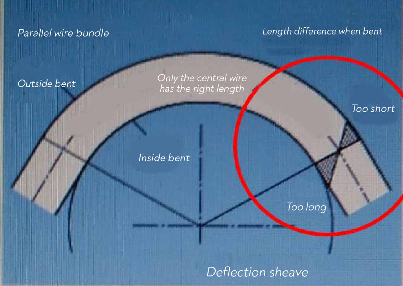
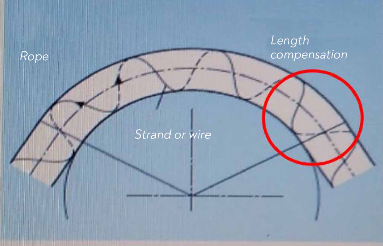
In the catalogue named PFEIFER-DRAKO_STEEL-WIRE-ROPES, the change in rope due to the bending is given with graphs. In Figure 1, only the middle part of the rope wrapped around a sheave remains at the normal distance while the lower side is longer than the normal position, and the upper side is shorter than the normal position. Moreover, the wires subject to pressure on sheave at the bottom put pressure on the upper part, as shown in the Figure 2. These forces on the rope cause the rope cores and wires of the outer and inner windings to rub against each other, the formation of more than expected forces on the wires due to unbalanced forces, wire breaks or bending fatigue.
Various publications on this subject are available online. Rolan Vetreet is a well-known practitioner and researcher on rope bending issues. “Calculating the service life of running steel wire ropes by Dipl.-Ing. Roland Vetreet” (Calculation of service life in the operating steel wire ropes) examined the rope bending issue in his publication. In this publication, the formula for rope bending of Prof. Feyrer from the University of Stuttgart was used. In this formula, we can see that the equivalent value of the rope bending depends on the rope diameter, the tension value, the sheave diameter, the affecting force, as well as other factors (such as b0, b1, b2, b3) that will be determined by the rope manufacturer by subjecting it to various tests.
In this formula
- N indicates the number of bending cycles
- d the nominal rope diameter in mm
- D the diameter of the sheave in mm
- S the rope line pull in N
- Ro the nominal tensile strength of the wire in N/mm2
fd takes into account the scale effect, fL the length of the most stressed rope zone and fE the type of rope core.
The factors b0 to b3 are rope-specific parameters which must be determined separately in a great number of bending fatigue tests for every single rope design.
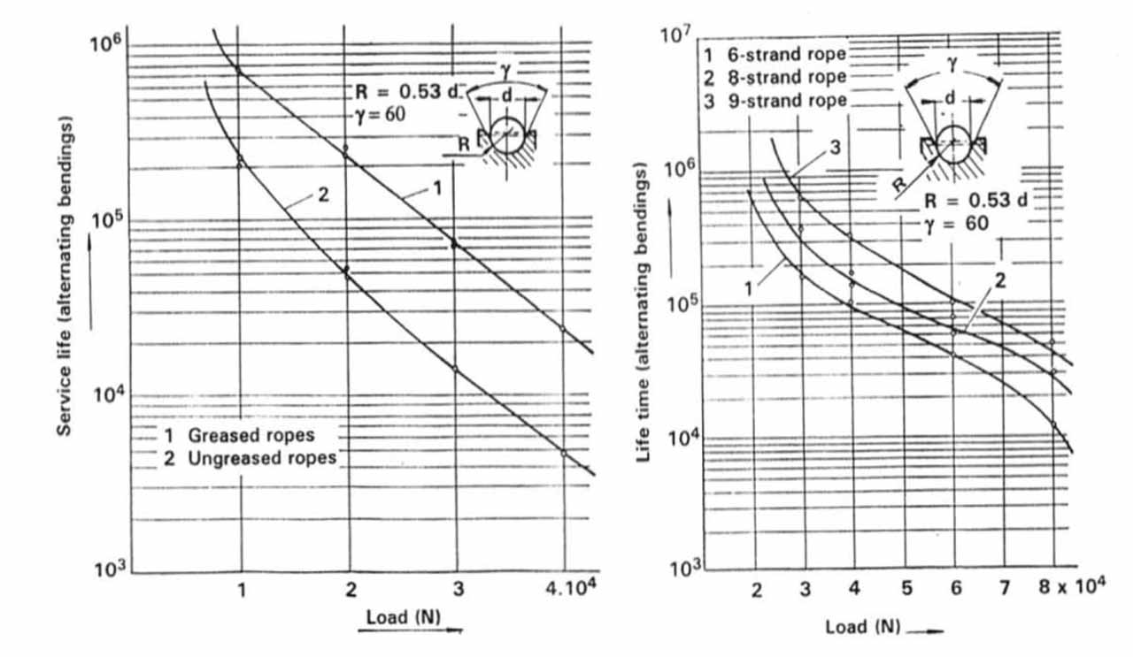
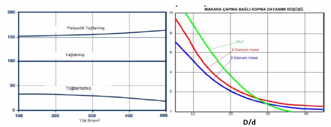
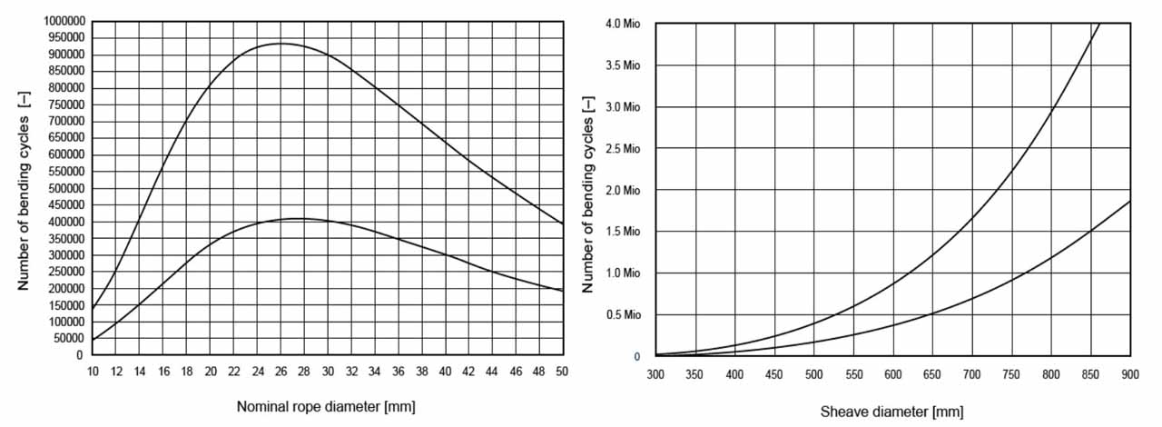
It is possible calculate the life of rope based on its properties and the place it is used. There are lots of tables that show these impacts by rope life. Some of these tables are given below. The graphs and their resources are listed as follows: the graphs in Figure 3, giving the changes according to the diameter of the rope and the diameter of the reel used, from “Calculating the service life of running steel wire ropes, Dipl.-Ing. Roland Verreet”; the graphs in Figure 4 giving the lifespans according to the number of cores or to the load state of steel or fiber ropes, from the book “Elevator Mechanical Design Third Edition, Lubomir Janovsky”; the graphics in Figure 5, giving the breaking strength due to the reel diameter depending on the lubrication condition of the rope and the number of wires, from the publication “Elevator Ropes Güven Kutay-Günhan Yanbay.” As can be seen from the graphs below, each factor has an impact on the lifespan of a rope. We cannot mention about a standardized calculation for the ropes, which means ropes should be used for each machine based on their own classification. Therefore, ropes should be chosen among those subject to Lift ropes EN 12385-5 standard. every steel rope is Not a lift rope. Rope sheave diameter rates and rope calculation principles given in the lift standard apply to ropes in this classification. The sheave diameter in ropes subject to EN 12385-5 standard on compression or deflection sheaves – whether straight or opposite direction – should be at least 40 times the rope diameter. This may change in specially certificated ropes.
Since each different bending leads to deformation on the rope based on its structure, the number and type of bending must be known to calculate factor of safety. The sheave, which is accepted as a unit to specify the bending intensity, is the one we call “idler,” which does not put additional pressure on the rope. It is stated in the EN 81-50; 5.12.2.1 that all bending should be equaled to a simple bend.
5.12.2.1 General
“The number of bends and the degree of severity of each bend cause deterioration of the rope. This is influenced by the type of grooves (U- or V- groove) and whether the bend is reversed or not. The degree of severity of each bend can be equated to a number of simple bends.
A simple bend is defined by the rope travelling over a semi-circular groove where the radius of the groove is not more than 0,53 of the nominal rope diameter.”
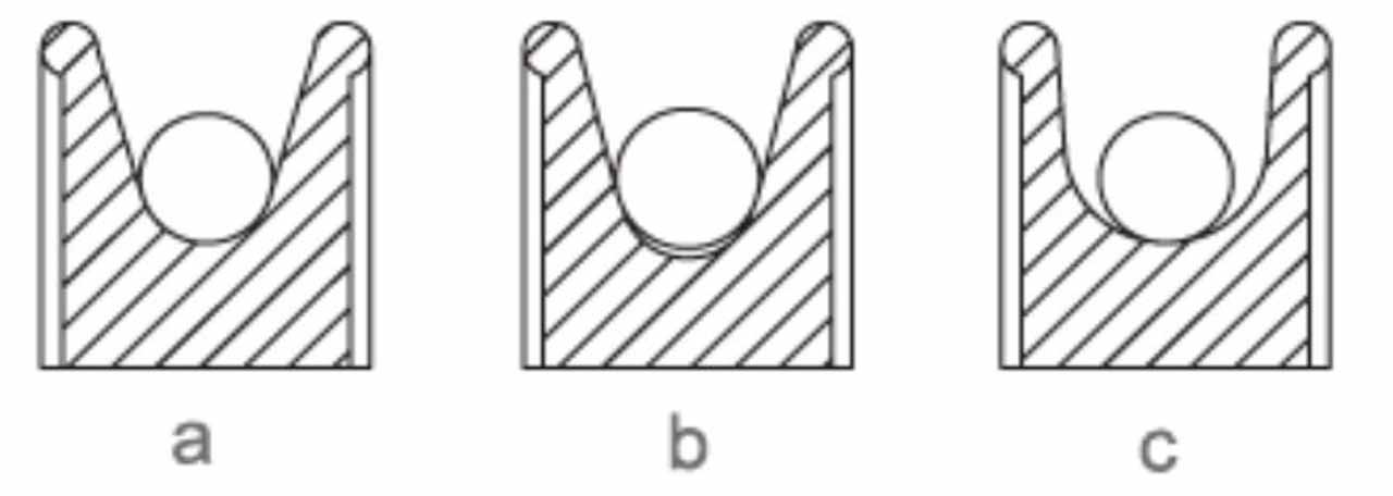
Simple bending is shown in option a. In option b, there is a compression on the rope while there is a spread on the rope in option c, thus, they are not accepted as simple bending. The traction ability in traction lifts occurs due to the friction between the sheave and rope. Therefore, traction sheaves compress the ropes and traction occurs due to the friction. However, the compression leads to deformation of ropes.

Compression of the ropes vary by the flank angles and undercut angles of the grooves. Table 2 of EN 81-50; 5.12.2.2 shows the simple bending equivalents of sheaves by their groove and angle status (NT). For U grooves and the channel radius of which is not greater than 0.53 of the nominal rope diameter, the equivalent number is accepted as 1 and taken as simple bending criterion. Note that a V-groove sheave with a 35 O groove angle corresponds to 18.5 simple bending. If the undercut angle is 105 degrees in the undercut U groove, it leads to a deformation equal to 15.2 simple bending.
Table 2 — Evaluation of equivalent number of traction sheaves Nequiv(t)
| V-grooves | V-angle (γ) | 35° | 36° | 38° | 40° | 42° | 45° | 50° |
|---|---|---|---|---|---|---|---|---|
| Nequiv(t) | 18,5 | 16 | 12 | 10 | 8 | 6,5 | 5 | |
U-Undercut grooves | U-angle(β) | 75 | 80 | 85 | 90 | 95 | 100 | 105 |
| Nequiv(t) | 2,5 | 3,0 | 3,8 | 5,0 | 6,7 | 10,0 | 15,2 |
Values for angles not in the table may be determined by linear interpolation.
The direction in which the traction sheave rotates in the lift is the main rotation direction, and all other sheaves rotation in this direction are considered straight bending. Standard EN 81-50; 5.12.2.3 also provides a method for the calculation of deflection sheaves other than the traction sheave. If the rope formed on the traction sheave encounters a different diameter deflection sheave (idler), an additional deformation occurs due to the diameter difference. This impact can be found by calculating the Kp factor. The formula for finding the simple bending sheave equivalent of deflection sheaves is given below.
Np = KP.(Nps+4Npr)
KP = (DT/DS)4
Nps = is the number of pulleys with simple bends;
Npr : is the number of pulleys with reversed bends;
KP : s the factor of ratio between sheave and pulley diameters.
DT : is the diameter of the traction sheave;
DS : is the average diameter of pulleys, traction sheave excluded
NT obtained from the graph. After the calculation of NS, the number of equivalent total simple bending sheave is found as NE. NE = NT+NS
Then, the necessary calculation are done to find rope safety factor (Sf ). ( EN 81-50; 5.12.3)
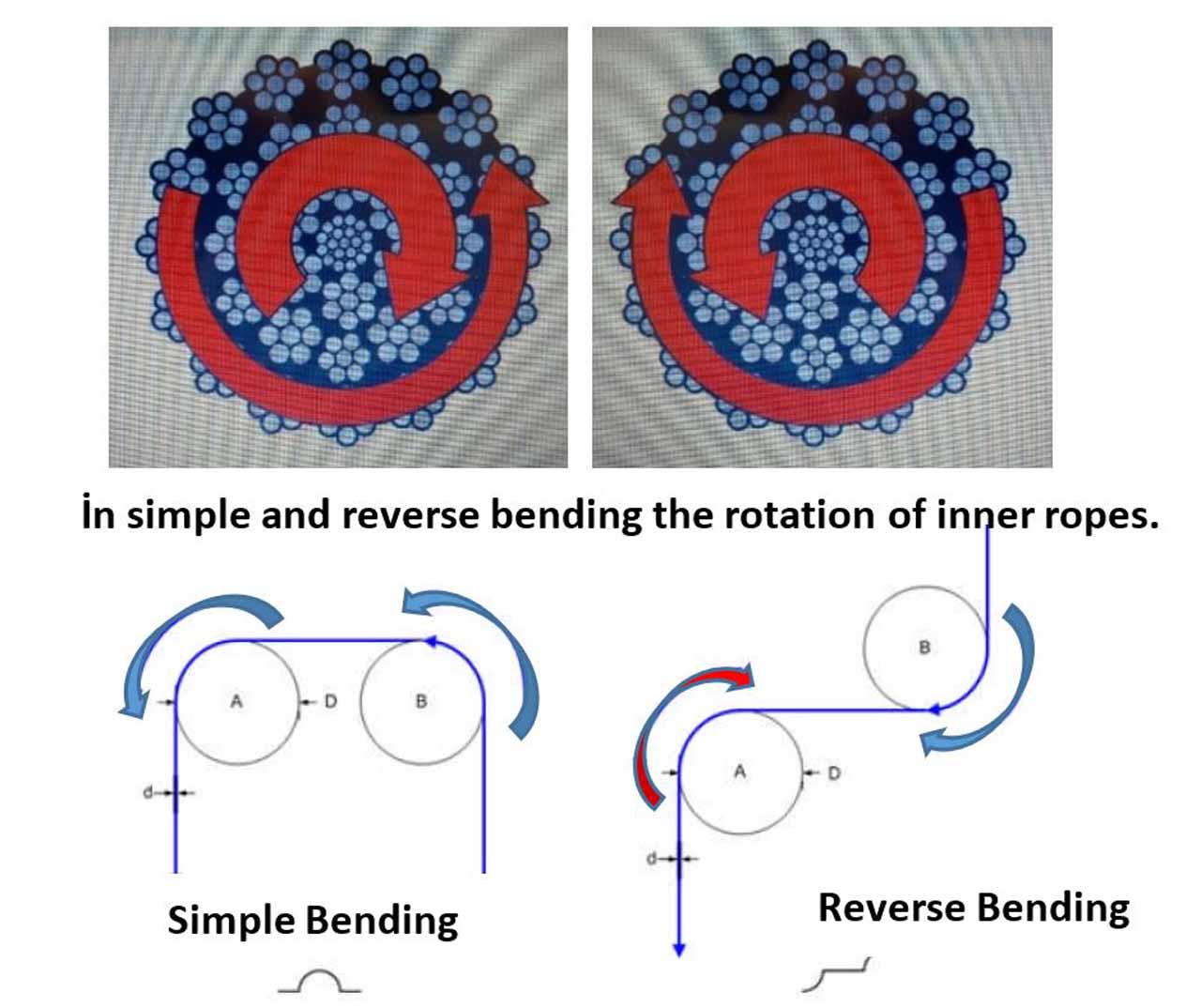
In the formula given above, Npr: reverse bending deflection sheave number is given. In order to find the deformation of these sheaves, a multiplier of four times that of the straight bending sheave is taken. The reason of this is that the straight bending rope takes shape according to the bending direction. It is reshaped when it is subject to reverse bending and there is much more friction and pulling than normal between the rope wires. In sheaves rotating in the same direction, the deformation will be less since the stretching and shaping of the rope will be in the same direction as well, but in reverse bending, the deformation of fibers will accelerate since the movements of rope wires on both sheaves will be different then.
In Figure 8, rotations and movements of the rope in two different bending are shown.
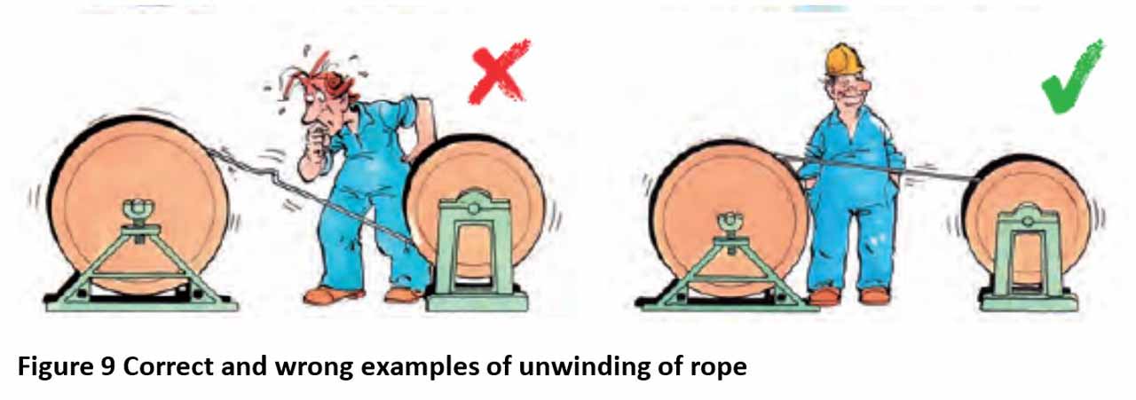
If the reverse bending sheaves are too close to each other, then the rope will be subject to a reverse bending before it has a chance to turn back its normal state. In this case, gaps, loops and nodes may occur between the internal and external coiling of the ropes. The pictures below are obtained from the catalogue named “Technical Information on Steel Rope” by Güven Çelik Halat.
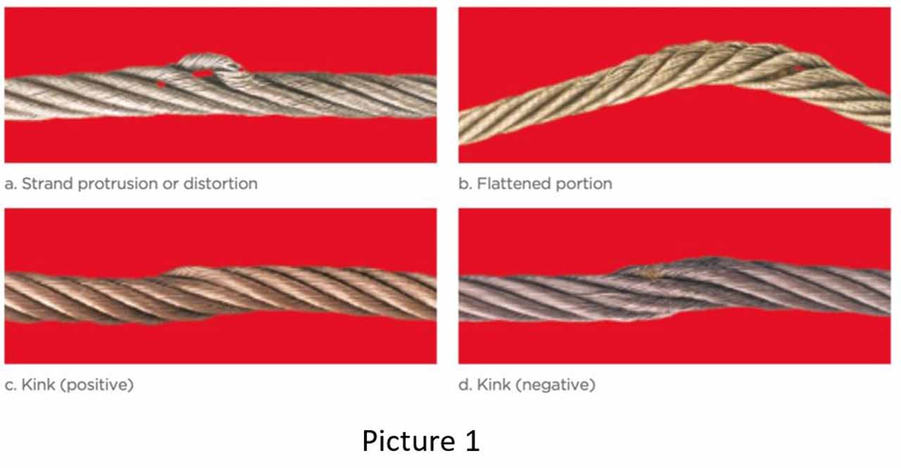
This can be clearly observed when the ropes are uncoiled from the pulleys and coiled onto the other pulley. In case of a reverse uncoiling effort, loops and eyelets.
Such reverse movements shorten the life span of a rope faster. EN 81-50 Standard defines the reverse bending on lifts in the article 5.12.2.3.
5.12.2.3 Evaluation of Nequiv(p)
“A bend is only considered to be a reverse bend if the distance from the rope contacts on two consecutive pulleys, which have a fixed distance between their axis, is less than 200 times the rope diameter and the bending planes are rotated through more than 1200.”
According to this definition, the reverse bending will be considered straight bending if the distance between sheaves is more than 200 times the diameter of the rope. Because the rope has recovered to its normal status and no deformation factor is needed to be taken as there will be no additional formation. Considering this article, even if the car and the sheaves connected to the counterweight are in a state of reverse bending, it is considered as straight bending. Although the standard specifies a maximum size, it does not impose a restriction for the minimum size in reverse bending. It is necessary to look at the rope user manuals and related articles for this.
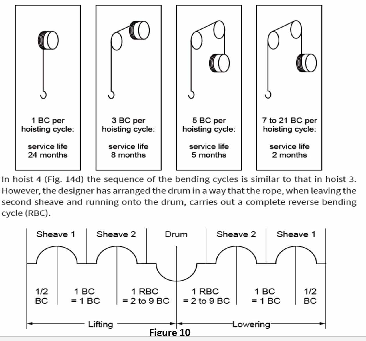
Roland Verreet has given examples for reverse bending in his above-mentioned article. The last example consists of a reverse bending in itself. Although it performs the same function as in the previous example, it is necessary to pay attention to the shortening of life of the rope due to the bending direction. If attention is paid to the changes in maintenance periods which should be performed according to the characteristics of bending, it is seen that the maintenance period in reverse bending should also be shortened. The values for straight bending cycle (simple bending) to be taken against the reverse bending are also given. It is shown in the fourth graph in the figure below that the reverse bending may correspond to the straight bending between 2-9. This number is taken as 4 in the lift implementation (as given in the formula above).
In the user manuals of various companies, the necessity of opening the distance between sheaves is noted as one of the main measures to be taken to minimize the impact of reverse bending. “Usha Martin Italia” stated in the ropes user manual that 100 times the diameter of rope can be taken as distance between sheaves for 90O reverse bending, and this distance can be taken less than 100O for wider angles. I cannot convey the explanations here since it is not allowed to publish the article, but those who are interested can download the brochure and view it. If the sheave rope angle is 90, L>100O but if it is lower than 90, L<100. This is close and conforms to the values given in the video.

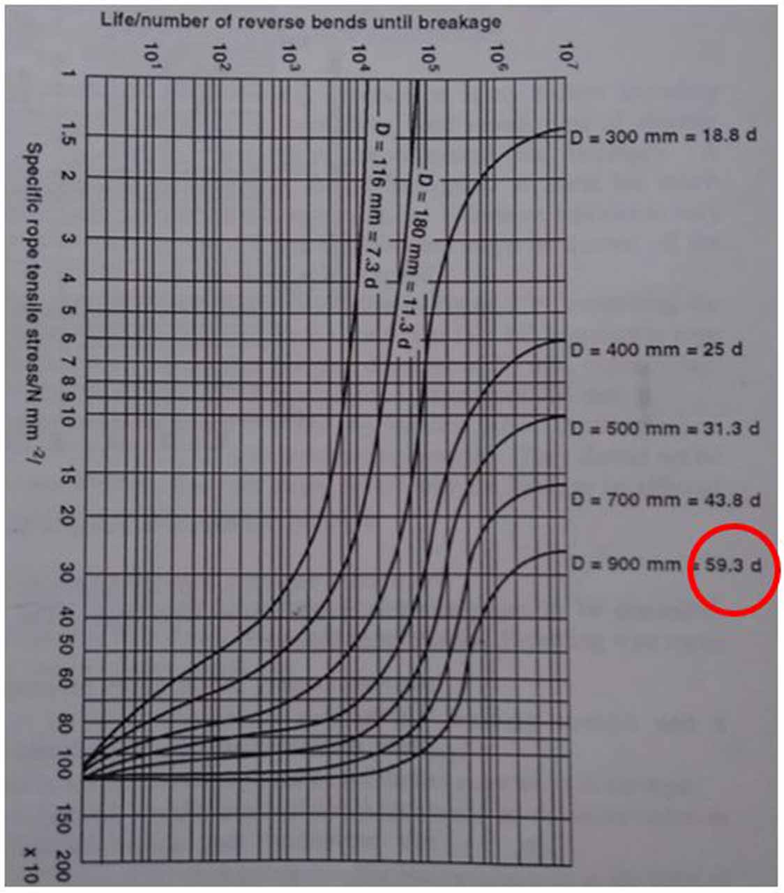
It is possible to find another study on this subject in the book named “Elevator Mechanical Design Third Edition, by Lubomir Janovsky”, which is an important mechanic design resource. In his book, Janovsky made a table showing the ratio of rope diameter to the distance in the studies of minimizing the impact of reverse bending. It is seen that the impacts of this bending reach to an acceptable level in approximately 60 times the diameter of the rope.
In 90s, the use of pressure sheave in lifts was quite widespread. Such implementations were frequently seen in the controls performed in those years. Rope breakage was quite common in installments where this practice was performed poorly. Rope reverse bending should be avoided as much as possible in lift practices. Such use of sheaves always poses a risk for the ropes and lift safety. Since reverse bending requires a greater safety factor, it also requires the use of a larger rope section. Transfers should be made in such a way that reverse bending does not occur in the transforms from the pulley, even during the rope uncoiling.
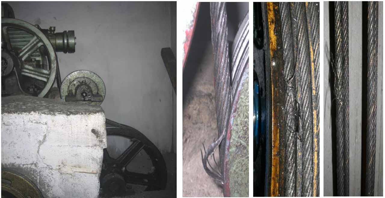
The Impact of Reverse Bending on Traction Ability
In reverse bending, 60 rope diameter distance between the sheaves can be seen as a condition of good engineering practice rather than a mandatory requirement, but the purpose of making this mandatory is more about safety than preventing rope wire breakage or prolonging rope life. During the lift inspection, the duty of the inspector is not to check the comfort or quality of the lift but to identify the existing risks. There is another risk of using reverse bending in the lifts besides the effect of rope breakage. The closeness the pressure sheave to the traction sheave leads to rope clamp and this may hinder the sheave condition required in item c of the article 9.3 in EN 81-1.
EN 81-1+A3; 9.3 Rope traction
“Rope traction shall be such that the following three conditions are fulfilled:
………
c) it shall not be possible to raise the empty car when the counterweight is resting on the buffers and the lift machine is rotated in the “up” direction.”
Rope clamp is a serious risk for lifts and can lead the cabin to directly crash onto the well ceiling without a retarding measurement (such as buffers). Since it is assumed that the rope will slide through the traction sheave if the counterweight is blocked, the car can slow down to stop in the upward direction by placing buffers under the counterweight. The aim of placing these buffers is to decelerate the car while moving upward direction. If the ropes do not slip, no safety measures will be taken in the upward direction for the speeds at which the regulator is not involved. During the testing, it has been observed that the clamp is not seen often in the lifts with a distance of 60 times the rope distances between the reverse bending sheaves, and the rope can slide towards the unloaded side. In later times, faulty practices can also be seen in the motor applications. Since rope clamping occurred in the applications shown below, the ropes did not slip on the sheaves and the car continued its upward movement although the counterweight was placed on the buffers in the well tests.
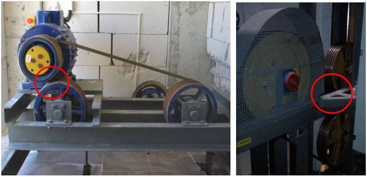
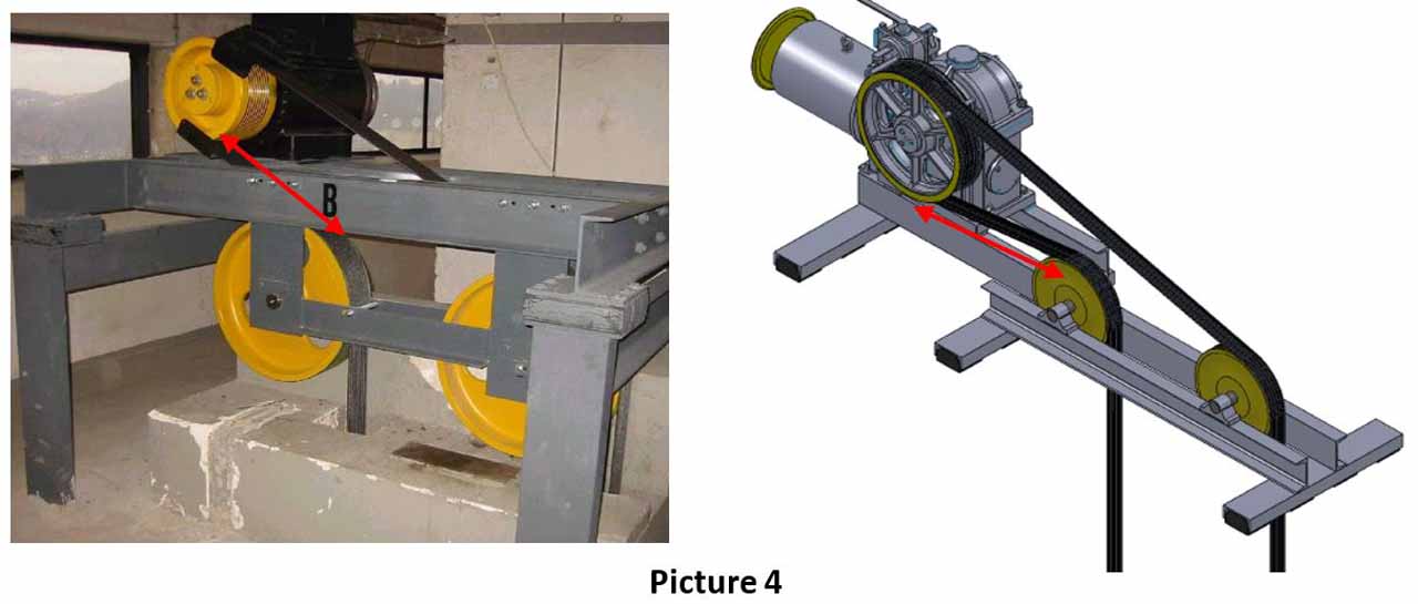
During the controls carried out in Izmir in 1998, research was made on this subject at the Joint Commission on Lift Controls and after examining various documents, it was accepted that a distance of 60 times the rope diameter between the sheaves in reverse bending was found appropriate in the Lift License Inspection (it was the name at that time). It was detected that rope breakage was relatively less common in practices with the appropriate distance between the compression sheaves and traction sheaves, and in many practices, the ropes could slide on the sheave without rope clamping. Academic research on this subject will also be beneficial. Instead of such practices where pressure sheaves or short rope return sheaves, the practices such as the ones below that leaves appropriate distances between the sheaves will give more accurate results.
Even if the practices are made as shown in the figures above, even if the appropriate distances are left, the rope clamp may occur depending on various factors such as the type of rope, number of deflection sheaves, groove type of the traction sheave used, the winding angle, reverse bending angle, the speed of the lift, the load type, and more. Each lift should be tested as defined in the article 6.3.3 of the TS EN 81-20 standard before it is put into operation.
EN 81-20; 6.3.3 Checking of the traction (5.5.3)
“The traction shall be checked by making several stops with the most severe braking compatible with the installation. ………
The counterweight shall be brought into contact with the buffer(s) and the machine shall continue to be turned until rope slippage occurs, or if slippage does not occur the car shall not be raised. It shall be checked that the balance is as stated by the installer.”
If the rope sliding does not occur on the sheave, the preventions specified in paragraph c) 2) of the article 5.5.3 Rope traction in TS EN 81-20 M should be taken.
EN 81-20; 5.5.3 Rope traction
“……….
c) it shall not be possible to raise the empty car or the counterweight to a dangerous position if either the car or the counterweight is stalled; either:
1) the ropes shall slip on the traction sheave; or
2) the machine shall be stopped by an electric safety device in conformity with 5.11.2.”
This requirement is recently added with the EN 81-20. If no sliding is seen, the car should be ensured to stop with a safety contact mechanism conforming to 5.11.2, apart from limit breakers. The fact that a distance of 60 times the rope diameter is used between reverse bending sheaves does not mean the ropes will slip from the sheave depending on the conditions mentioned above. In each lift, slippage should be tested depending on its specific features and the necessary safety measurements should be taken. Meeting the requirements of the standard is essential. In such lifts, placing buffer under the counterweight should be seen as a sufficient precaution for slowing down the car coming to a halt in the upward direction, and a car suspension and a buffer application on the well should also be performed. Because it is the car that needs to be protected, not the buffer. Reverse bending practices should be avoided on ropes unless it is a necessity.
Get more of Elevator World. Sign up for our free e-newsletter.
