Rope-Drive Elevators
Oct 1, 2015

Otis’ turn-of-the-20th-century designs for a unique elevator drive shaped the modern traction elevator.
The invention of new elevator systems has often followed a distinct developmental trajectory: inventors pursue a main or primary path that encompasses what eventually becomes the standard system, while simultaneously pursuing one or more secondary parallel paths. These secondary paths, which may be thought of as variations on the main theme, are often driven by an almost obsessive desire to solve what are perceived to be critical problems associated with the new system. These pursuits are typically brief, highly focused design exercises that occasionally produce their own unique (and often overdesigned) systems. Such was the case in the development of the modern traction elevator. It appears that the simplicity of the initial concept – a system of cables connecting the car and counterweights and passing over and around traction sheaves – prompted a host of concerns about cable slippage and wear due to excessive friction, as well as concerns about direct-connected electric motor speeds and the associated speed of the driving sheave. One proposed solution to these problems was the rope-drive elevator.
Two of the first rope-drive elevator patents were awarded to Norman C. Bassett, an engineer with Thomson-Houston Electric Co.: “Gearing for Elevators,” U.S. Patent No. 483,203 (September 27, 1892) and “Gearing for Elevators,” U.S. Patent No. 485,163 (November 1, 1892). The applications for both patents were filed on October 11, 1890; thus, Bassett saw his patents as articulating variations of a common invention. Bassett’s design was predicated on the belief that, with traction elevators, “one of the principal difficulties. . . arises in the excessive loss by friction, which is unavoidable when the weight of the total load is brought to bear upon the armature of the motor or other fast-running parts connected therewith.”[1]
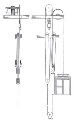
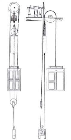
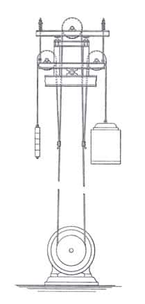
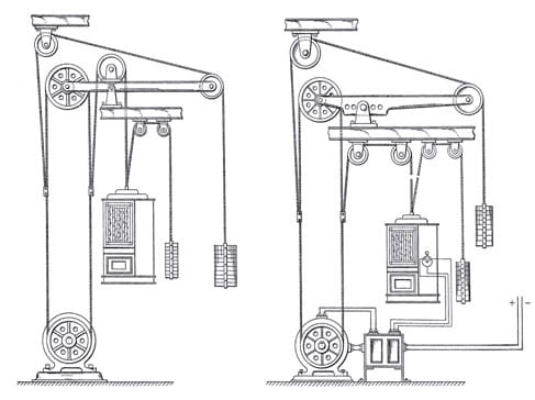
Bassett described his solution to this problem as “an effective and noiseless mechanism for transmitting the power and reducing the high speed of the motor to the comparatively slow speed of the car.”[1] He accomplished this by placing the electric motor and driving sheave adjacent to the hoisting sheave such that the driving sheave powered a “rope-and-pulley device” connected to the counterweight (Figure 1). The rope-and-pulley device moved the counterweight, and, thus, the car, paccording to Bassett, effectively transferred the “main portion of the load” from the “fast moving” driving sheave to the “slow moving” hoisting sheave, thus “greatly” reducing the “loss due to friction and wear.”[1] His second patent described the “power-transmitting mechanism” as a “differential rope device” (Figure 2).[2] It is of interest to note that, in both patents, Bassett consistently used the word “drum” when referring to the traction sheaves.
Bassett’s rope-drive elevator concept apparently attracted little attention until the early 20th century, when Otis became interested in this alternative version of the traction elevator. On January 7, 1903, Rudolf C. Smith, one of Otis’ leading engineers, filed an application for “Rope-Drive for Elevators,” U.S. Patent No. 789,765, which was awarded on May 16, 1905. In it, Smith clearly expressed his awareness of Bassett’s design:
“This invention relates to a rope-drive for electric and other elevators, the object being to provide a simple and effective apparatus with a minimum of friction and consequent minimum of wear and tear. The present invention is a modification of the device shown in U.S. Patent No. 483,203, dated September 27, 1892, issued to Norman C. Bassett. This invention describes an arrangement of pulley-blocks for a rope-drive in combination with a car which is connected to a balance weight by means of additional independent cables in such a manner that only a fractional part of the unbalanced load has to be overcome when set in motion by the motor.”[3]
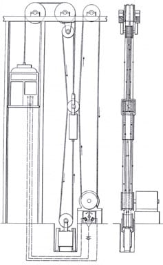
As was the case with Bassett, Smith connected the car and counterweight via a simple cable and sheave system, which was driven by an electric motor connected to a driving sheave that operated a secondary system (Figure 3). He described his secondary system as “two sets of multiple or reducing blocks and tackle,” which acted in opposite directions and, thus, were capable of raising or lowering the counterweight and car.[3] According to Smith:
“It will be evident that the load to be lifted or lowered is only the difference between the car and its load and the counterweight, and that according to the extent of the reducing action of the blocks and tackle, the draft upon the motor is reduced, while the same may rotate at a high speed.”[3]
Smith’s patent was the first in a series pursued by Otis engineers. The level of the company’s interest in the development of this system type is indicated by the 10 additional rope-drive patent applications filed between 1903 and 1909. Four applications were filed in both 1906 and 1908; thus, the peak period of research appears to have been from late 1905 to early 1909. However, accurately tracing this research trajectory requires the use of the patents’ application date. (The time gap between application and award ranged from seven months to six years). Thus, the following selected survey of these patents does not follow the sequence in which the patents were awarded, but the order in which their applications were filed (Table 1).
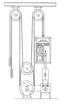
The design found in Ernest Boening’s patent “Friction-Rope-Drive Elevator,” U.S. Patent No. 932,432 (August 31, 1909), followed the paradigm established by Bassett and Smith and employed separate driving and hoisting sheaves connected by intermediate sheaves and ropes. One of Boening’s goals was to “provide a simple and efficient means for automatically maintaining the tension on the driving-ropes of such elevators.”[4] His design was predicated on the use of a “hinge-block” to obtain the needed “frictional contact” between the ropes and the driving sheave. Balanced atop the hinge-block was a supporting beam that carried the hoisting and secondary sheaves. (The motor and driving sheaves were located directly below the secondary sheave.) The supporting beam also featured massive springs at either end intended to “take up” any jarring or vibrations that occurred. Boening described his design as “a tilting leverage system” that automatically produced “a strain upon the loop of the rope or ropes which are between the driving sheave and the overhead sheave.”[4] He believed that the resulting “frictional contact or tension” would be “proportional to the weight of the car and its load.”[4] The complexity of his scheme is clearly indicated in the two versions that employed counterweights (Figure 4).
John D. Ihlder’s “Rope-Drive Elevator,” U.S. Patent No. 1,016,691 (February 6, 1912) offered a much simpler design solution, which somewhat resembled a normative traction system. According to Ihlder:
“The usual way of driving the car has heretofore been to lead the driving rope around the driving sheave and from thence around the loose sheave, back again to the counterbalance. . . . This produces a very heavy strain upon the bearings of the driving sheave or drum, as well as on the loose or tension sheave.”
This “heavy strain” was relieved by separating the hoisting and driving sheaves and employing multiple ropes. However, unlike earlier designs, this system employed a relatively simple set of additional components (Figure 5). In fact, Ihlder noted that his design was not as complex as it appeared in his drawings:
“For the sake of facilitating the tracing of the different ropes, I have shown the sheaves as of different diameters, respectively, and designated them as if they were, in each instance, separate sheaves. It should be understood, however, that the sheaves are substantially of the same diameter and fixed to each other; or, said sheaves may be a single sheave, with a double groove for the ropes. [The system was designed to] relieve the strain of power-transmitting means on the frictional driving apparatus [and to provide an effective] means for counteracting the strain on the bearings of the driving sheave and tension sheave of [the] traction elevator apparatus.”[5]
It is, perhaps, somewhat surprising that the subsequent eight patents primarily addressed variations on Boening’s (rather than Ihlder’s) design. The evidence that reveals Otis’ focus on the more complex hinge-block scheme is also accompanied by hints that several of these machines may have actually been built (if only in Otis’ testing facilities). David Lindquist’s and August Sundh’s “Rope-Drive Elevator,” U.S. Patent No. 987,384 (March 21, 1911) was described as an improvement “in traction or direct drive” elevator systems. The design had the integrated goals of providing a “simple and effective means for producing the necessary tension upon the traction driving cables” and providing a “means for distributing the tension on the driving cables upon opposite sides of the traction driving sheave.”[6] This was accomplished by using the car and counterweight to produce the requisite tension on the hoisting sheave ropes, with the car also counterbalanced to account for variations in load. A “pivot point” and beam (similar to Beoning’s hinge-block) was also employed to provide “a simple and efficient means for giving the requisite traction under all conditions of load without in any way complicating the system of roping or employing additional weights.”[6] The inventors’ claim of this design constituting an uncomplicated solution is, of course, debatable. However, they did clearly imply that their design had been built and tested. They stated that their elevator had “demonstrated in actual practice” both its efficiency and an additional benefit: it apparently helped to “overcome” the tendency of the car to “bound” (or, bounce upward) when stopped suddenly.
The last patent in this sequence was Lindquist’s “Rope-Drive Elevator,” U.S. Patent No. 931,935 (August 24, 1909). Lindquist characterized his design in familiar terms:
“The object of this invention is to automatically increase this frictional contact at different parts of the operation. During most of the operation of an elevator of this type, it is necessary to have only enough tension on the driving ropes to prevent slipping of the ropes on the driving sheave when the latter is at rest or to drive a light load on the car. With my invention, this tension and consequent friction is increased whenever the load in the car is increased, and this increase of friction may, by proper arrangement of the parts, be made proportional to such increase of load.”[7]
It is, perhaps, appropriate that this final scheme appeared to combine the simplicity of Ihlder’s design with Beoning’s complexity, with the latter seen in the wedding-cake-like arrangement of hinge-blocks, tilting levers, springs, and primary and secondary sheaves and ropes (Figure 7).
The thoughtful, focused, quietly obsessive and idiosyncratic quality of Otis’ rope-drive elevators speaks of a dedicated attempt to solve an apparently simple problem by the most complex means possible. The seriousness of this pursuit is revealed by the fact that many of the patents include detailed mathematical explanations of the elevator’s operation. Yet, it remains difficult to imagine that Otis’ talented cadre of engineers actually envisioned these machines being employed in America’s buildings and existing elevator shafts. It may, therefore, be appropriate to view these explorations as the engineering equivalent of a “thought experiment,” a philosophical concept typically defined as “a device of the imagination used to investigate the nature of things.”[8]
References
[1] Norman C. Bassett, “Gearing for Elevators,” U.S. Patent No. 483,203 (September 27, 1892)
[2] Norman C. Bassett, “Gearing for Elevators,” U.S. Patent No. 485,163 (November 1, 1892).
[3] Rudolf C. Smith, “Rope-Drive for Elevators,” U.S. Patent No. 789,765 (May 16, 1905).
[4] Ernest Boening, “Friction-Rope-Drive Elevator,” U.S. Patent No. 932,432 (August 31, 1909).
[5] John D. Ihlder, “Rope-Drive Elevator,” U.S. Patent No. 1,016,691 (February 6, 1912).
[6] David Lindquist and August Sundh, “Rope-Drive Elevator,” U.S. Patent No. 987,384 (March 21, 1911).
[7] David Lindquist, “Rope-Drive Elevator,” U.S. Patent No. 931,935 (August 24, 1909).
[8] James Robert Brown and Yiftach Fehige. “Thought Experiments,” The Stanford Encyclopedia of Philosophy (Fall 2014 Edition), Edward N. Zalta (ed.).
Get more of Elevator World. Sign up for our free e-newsletter.
