Rope Dynamics
Jul 1, 2011

This study explores how transient vibrations arise and why rope vibrations occur.
by Phil Andrew, MSc, MPhil and Stefan Kaczmarczyk, PhD
Rope vibrations in an elevator system usually result in a ride quality that is unacceptable. A well-known phenomenon is “transient” vibration, which occurs at a specific point in the elevator travel, usually near the upper floors, and can be extremely difficult to eliminate. We will seek to show that oscillations in the roping system may be considered “rapid” in comparison with the rated speed of the elevator (even for “high-speed” elevators rated at 12 mps [2400 fpm] or more). We will show how, for the purpose of analyzing the dynamic behavior of the roping system, a moving elevator may be considered “quasi-stationary.”
Hamilton’s Principle and classical mechanics will be employed to derive the dynamic equations that describe the oscillation of the ropes. The resulting partial differential equations will be presented in order to explain how lateral and longitudinal oscillations in the suspension system turn out to be cross coupled, so that a lateral oscillation of the ropes can initiate longitudinal vibrations and vice versa. Finally, we will work through an example to show how transient vibrations may arise at particular locations in the elevator travel and highlight why such rope oscillation and vibration is so difficult to eliminate, and look briefly at some of the solutions to the problem that have been proposed in the past.
Suspension System Dynamics
There are likely very few elevator engineers who have not been faced with an elevator system exhibiting unwanted vibration in one form or another. The underlying causes of vibration in an elevator system are varied, including poorly aligned guide-rail joints, eccentric pulleys and sheaves, systematic resonance in the electronic control system, and gear and motor generated vibrations.
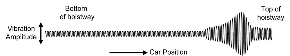
In many cases, an elevator will not vibrate throughout its travel, but will “pass through” a resonant vibration at some particular stage in the travel. Very often, this vibration stage occurs at or near the highest floor, as the suspension ropes be-come short. Figure 1 indicates the kind of phenomenon that might be experienced.
However, whatever the underlying cause of the vibration, in almost all cases, the vibration will excite an associated vibration in the ropes, whether it be the suspension ropes or the compensation ropes. The vibration is thus coupled into the car with consequent deterioration in ride quality. The term “vibration” has colloquial connotations of relatively high frequency and may be confusing if we intend to include “rope sway” in the discussion. Consequently, we shall employ the term “oscillation” in preference to “vibration,” since this term has a colloquial context of a wider frequency range.
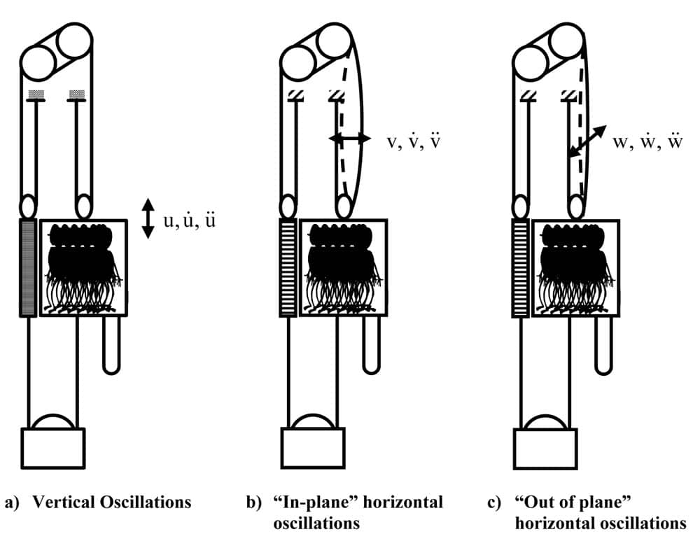
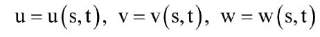
Let us start with a simple model. Consider the suspension and compensation ropes of a stationary elevator. As we have discussed, the suspension will be stretched elastically by the mass of the elevator and its load. In the vertical direction, the elevator car is free to move and can oscillate on the “spring” of the suspension ropes as shown in Figure 2(a). We shall designate oscillations in the vertical direction by the variable u, indicating vertical displacement from the quiescent position, ˙u indicating the vertical velocity of the oscillation of the elevator car (i.e., not its velocity of travel through the hoistway) and ü indicating vertical acceleration associated with the oscillation.
Since the elevator car is held in the guides and cannot move freely in the horizontal direction, lateral oscillations of the suspension ropes are constrained at each end. The oscillations are constrained in a similar (though not quite identical) manner to a guitar or violin string (Figure 2(b)
and (c)). Nevertheless, the rope can oscillate in any horizontal direction. In order to generalize the discussion as far as possible, we will resolve the lateral oscillations into orthogonal displacements, v, v˙ and ¨v indicating mo-tion in the plane of the guides (in plane), and w,˙w and ¨w orthogonal to the plane of the guides (out of plane).
Thus, if the ropes oscillate in a direction x at some angle q to the plane of the guides, then the in-plane and out-of-plane motions will be
v = x cosƟ, v˙ = x˙ cosƟ and v¨ = x¨ cosƟ
in the plane of the guides, and
w = x sinƟ, w˙ = x˙ sinƟ and w¨ = x¨ sinƟ in the orthogonal plane.
Of course, we might have a situation where the ropes are “whirling” in their oscillations; in which case the angle Ɵ will itself be a function of time, i.e., Ɵ = Ɵ (t).
The nature of current suspension-rope materials is such that the damping of any rope vibrations is fairly small.
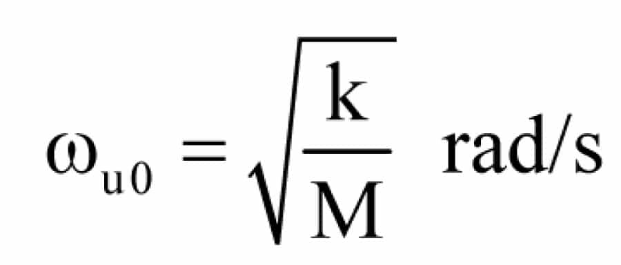
An analysis of rope oscillation based on elementary mechanics might indicate that if M is the total suspended mass (kg) (not including the mass of the suspension ropes) and k is the stiffness of the ropes (N/m), then in the vertical plane, we would have a potential “natural” or “resonant” oscillation frequency:
Even if we did allow for the mass of the suspension ropes, the simple model above does not reflect the true situation. In practice, there will be additional harmonic frequencies that can lead to phenomena apparent to the passenger.
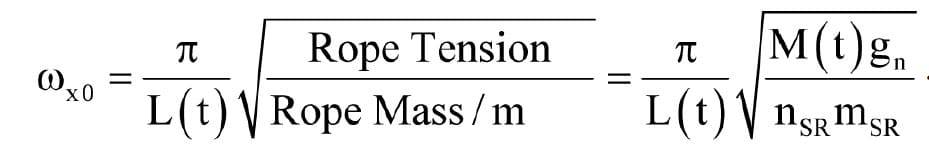
In the lateral direction, we might expect oscillation frequencies
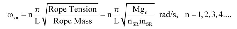
where L is the length of suspension rope, nSR is the number of suspension ropes and mSR is the mass/m of the suspension rope, noting once more that Mgn, the equation for rope tension, does not include the mass of the suspension rope itself. With lateral oscillation, even a simple analysis indicates that harmonic frequencies are possible.
Although this gives us an intuitive idea of what we might expect, the situation is significantly more complex. In order to get a more realistic picture of the oscillation modes of the suspension ropes, we will have to take into account more complex phenomena than we have considered so far.
The “Slowly Varying” System
The first complicating factor is the issue raised by the motion of the elevator car itself. Our simplistic picture of the oscillation mechanisms has been based on a stationary elevator car; in practice, the elevator may be in motion, so that the length of the suspension ropes is changing with time. The suspended mass M(t) and rope length L(t) are now functions of time. The suspended mass M(t), which still does not account for the mass of the suspension ropes, will vary due to the changing mass of compensation ropes/chains and traveling cables suspended from the car as the elevator travels through the hoistway. Even in our simplistic model, the stiffness k will vary as the length of the ropes changes, varying the longitudinal frequency ꙍu0, and, of course, the change in length directly affects the lateral frequencies ꙍxn.
Kaczmarczyk[1] has shown that we can define a dimensionless parameter
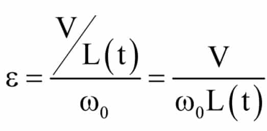
where V is the elevator rated speed (mps), ꙍ0 rad/s is the lowest natural frequency (either lateral or longitudinal), and L(t) is the suspension rope length (m).[1] Note that the issue here is not the speed of the ropes, but the rate at which the ropes are shortening. Consequently, independent of the reeving (1:1, 2:1, etc.) the parameter ε is a function of elevator speed, not rope speed.
Kaczmarczyk (ibid.) reports that if we can be satisfied that
then we can define the system as varying slowly, meaning that we can take any particular position of the elevator, whether or not it is in motion, and treat it as if the elevator were stationary.[1]
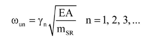
Looking at lateral oscillations of the ropes, the elementary treatment referred to above suggests that the natural frequency of the ropes will be
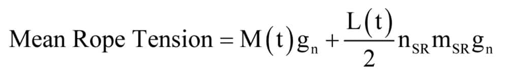
However, this simple equation assumes that the rope itself has zero bending stiffness and is orientated horizontally. Sun[2] suggests that for a more ac-curate estimate of the mean natural frequency of a vertical suspension, we need to account for the influence of the rope mass on the mean tension. The mean rope tension T needs to include half the weight of the rope, i.e.
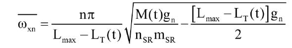
Including lateral harmonic oscillation frequencies as well as the natural frequency, Equation 4 then becomes

The term ![]() inside the square root sign suggests that the natural frequency of the oscillation will be higher than is suggested by the simple analysis of a horizontal, stretched string, and that with longer ropes (i.e., longer travel), the natural frequency of the ropes will not fall off as rapidly as would be predicted by the simple model of Equation 4. Nevertheless, the frequency will still be at a minimum when the car is at the lowest point of travel, leading to the largest value for e. If we define Lmax as the rope length when the car is at the lowest point in its normal travel, then
inside the square root sign suggests that the natural frequency of the oscillation will be higher than is suggested by the simple analysis of a horizontal, stretched string, and that with longer ropes (i.e., longer travel), the natural frequency of the ropes will not fall off as rapidly as would be predicted by the simple model of Equation 4. Nevertheless, the frequency will still be at a minimum when the car is at the lowest point of travel, leading to the largest value for e. If we define Lmax as the rope length when the car is at the lowest point in its normal travel, then
Given that the loading on the ropes is governed by safety standards, we can relate Equation 5 to the rope characteristics via the guaranteed minimum breaking load of the rope and the safety factor.
We will define SfM as the factor of safety at the lowest point of travel (varying, mainly depending on passenger load but also due to changes in total car side suspended mass as the elevator travels through the hoistway), and Fmin as the specified minimum breaking load for the rope. With these definitions, then at the lowest point of travel
Combining Equations 5 and 6, the lowest mean natural frequency can be expressed as
Combining Equations 2 and 7, and given that, in practice, the lateral oscillation frequencies will be lower than the longitudinal frequency, the largest value of e will be
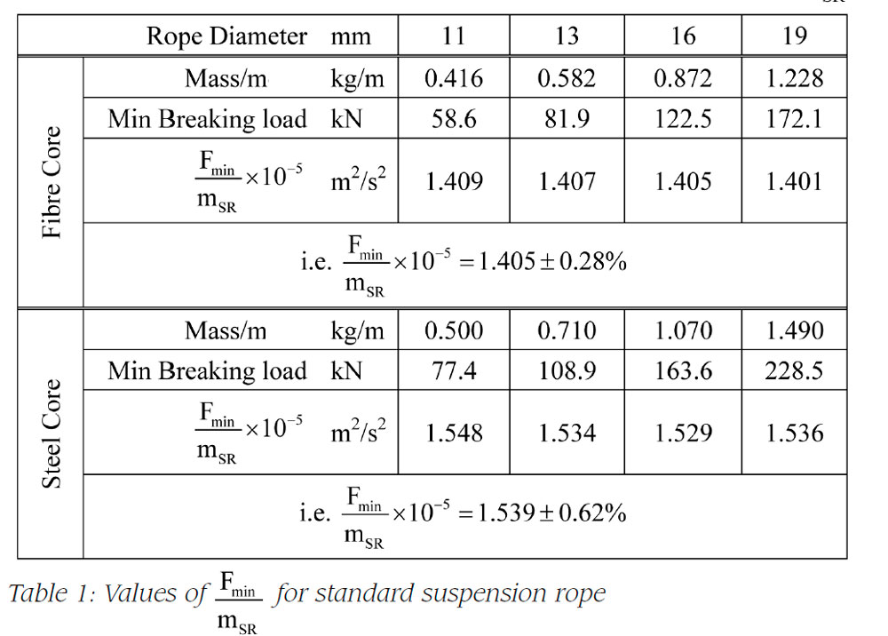
Taking the rope tables for a range of standard, fiber-cored suspension ropes, we can examine the value of 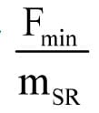 for various rope sizes and safety factors. Unsurprisingly, Table 1 shows that for any given value of safety factor Sf, the value of does not vary significantly in the range of standard rope sizes between 11 mm and 19 mm.
Clearly, the material tensile stress at the minimum breaking load will be the same, and for similar rope construction, the rope space factor (steel area: total area) will also be reasonably constant, leading to the steady value for
With significantly smaller rope sizes, as are applied in some special designs, the space factor of the rope will begin to change, modifying the calculated value of Of course, during system design, the minimum permissible safety factor will be determined for the case where the elevator car is carrying rated load, taking into account both standards requirements and the constraints of achieving a satisfactory rope life.
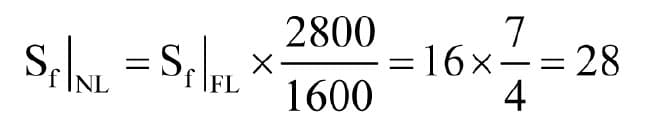
Any other loading is accounted for by calculating the higher safety factor associated with the lower loading, e.g., if the rated load is 1200 kg and the car-side fixed mass is 1600 kg, then if the system is designed for a safety factor of 16 at rated load, the safety factor with empty car will be
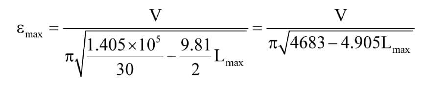
If, as a conservative estimate, we base our analysis on an empty car with maximum factor of safety value 30, then Equation 8 becomes
We can now investigate emax for a range of rated speed and travel. For this purpose, we will take the maximum practical travel as the lesser of 300 m or the travel distance the elevator can complete in a maximum of 60 s, allowing for constant acceleration/deceleration pro-files at 1 mps2 (i.e., ignoring limitations imposed by jerk requirements).
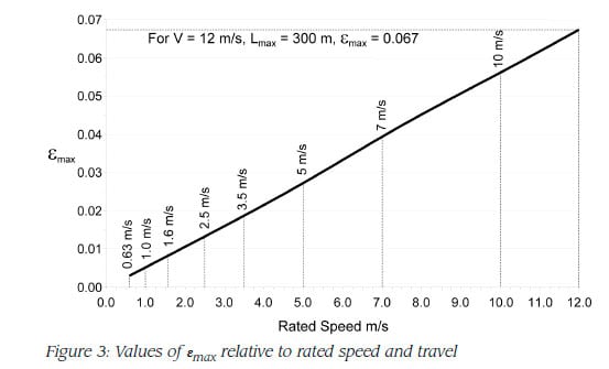
The result is shown in Figure 3, demonstrating that with this conservatively high estimate for factor of safety and maximum travel, we can say that at a rated speed of 12 mps,
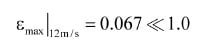
allowing us to treat the elevator as quasi-stationary. Furthermore, given that experience shows that the problems usually arise near the upper limit of travel, in the area of interest in the hoistway the actual value of ε will be significantly lower than this maximum estimate. It turns out that at a rated speed of 12 mps, the value of e at the slowdown point for the upper terminal floor is in the order of 0.052.
The Dynamic Model
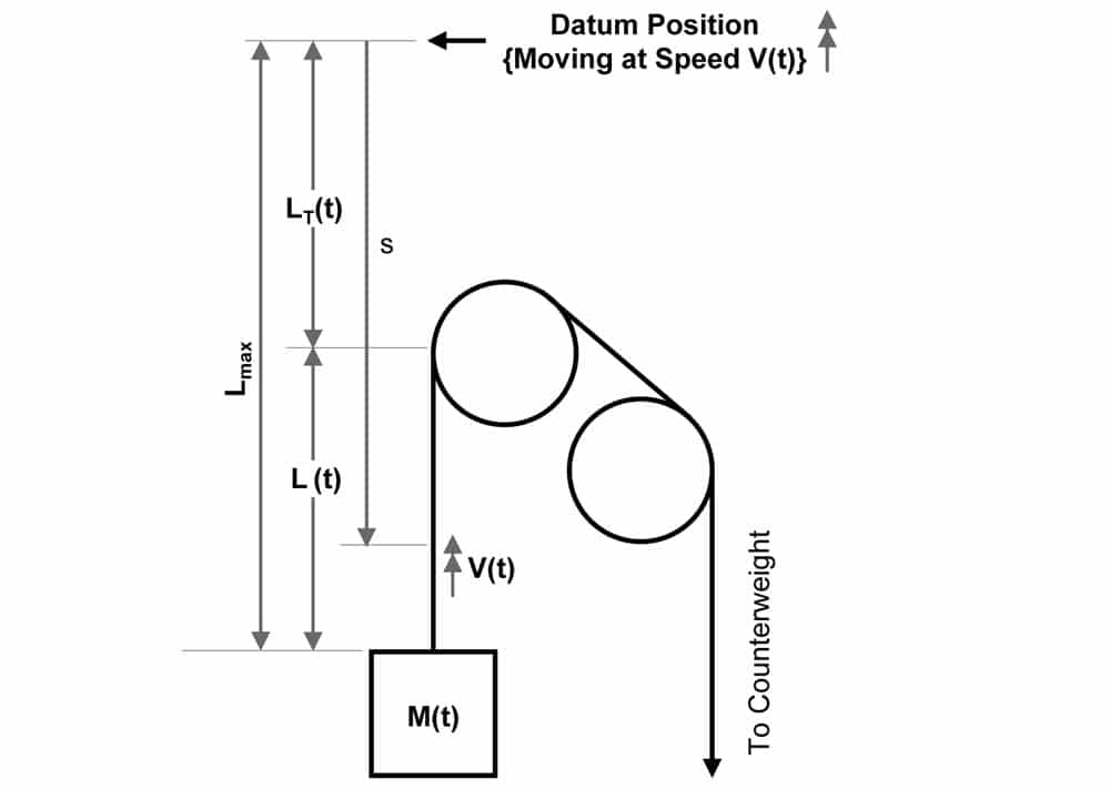
Figure 4 shows a suitable dynamic model of the elevator system. In order to make the mathematics of the analysis more straightforward, the model employs a “moving frame of reference.” In the model, all the distances are measured from a moving origin located at a fixed distance Lmax above the car top, where Lmax (m) rep-resents the suspension-rope length when the car is at the lowest position. Thus, LT(t) represents the distance traveled by the car (m); V(t) is the elevator car speed (mps); M(t) is the car-side mass (kg) including the mass of any compensation ropes/chains, travelling cables, etc.; msr is the mass per unit length of the rope (kg/m); T(t) is the mean rope tension; A is the rope cross sectional area (9 mm2); and E is the Young’s modulus for the rope (N/mm2).
Now we need some very clear thinking. If the ropes are still, i.e., not oscillating, then we can define a variable s to represent the position of any point along the length of the rope, relative to the (moving) datum position. In these conditions, we can say that the rope is “un-deformed,” since it is only stretched by the suspended mass. At the extreme end, s = Lmax is the mean position of the point where the suspension meets the car top.
If a rope begins to oscillate, either vertically or later-ally, it becomes dynamically deformed, i.e., a given point will be displaced from its quiescent position, s meters from the datum, by the (relatively) small amounts ±u (vertically), ±v (lateral in plane) and ±w (lateral out of plane).
Now let us examine what is happening if the system is in motion and oscillating. We will assume for the moment that the elevator machine and control system are “very stiff,” i.e., any oscillations in the ropes are not propagated beyond the point where the ropes come into contact with the sheave (the oscillations might themselves be initiated by oscillation propagated from the machine and/or control system, but since we are looking at the dynamics of the ropes themselves, we are assuming here that there is no “forcing function” coming from the sheave). Since, in terms of motion through the hoistway, the system is “slowly varying,” we can consider the motion of a point at position s along the ropes as if the elevator were actually stationary except for the oscillations. In these circumstances, the total energy in the system would be constant, and we can apply Hamilton’s Principle [1], which states that over time, the time integral of the difference between the kinetic and potential energy in the system will be stationary. Note that in the context of the elasticity of the ropes, the potential energy of the system includes the strain energy in the ropes themselves. In mathematical terms,
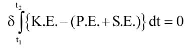
where δ represents variation, K.E. is the system kinetic energy, P.E. is the gravitational potential energy and S.E. is the strain energy.
Be very clear about what Equation 10 means and what it doesn’t. If the elevator car is accelerating downward, then the total kinetic energy of the system is increasing due to the acceleration, and the total potential energy is reducing, since motion is in the down direction (assuming that the car mass is greater than the counterweight mass). Conversely, if the car is slowing while traveling upward, total kinetic energy is reducing, while total potential energy is increasing.
However, that is not the issue we are discussing here. Instead, we are taking a “snapshot” of the elevator car in motion at some point in the hoistway and looking at how the energy in the system at that instant is being transferred between the oscillatory motion of the ropes (˙u, v˙, w˙ , and ü, ¨v, ¨w), the position of the point on the ropes (u, v, w) and the strain energy in the ropes. Of course, u, v, w and their time derivatives will vary depending on where we measure them along the rope, i.e., they will depend not only on time, but also on s, the location along the rope, so that at the moment when we take our snapshot, each is a function of both s and t. Again, in mathematical terms
To get any further with this analysis, we would need to go into the mathematics of classical mechanics. However, for the elevator engineer, it is the outcome of the analysis that is important, not the analysis itself. The outcome is a set of differential equations describing the oscillatory motion. We are not going to attempt any solution of these equations here, but simply present them to demonstrate that the three displacements u, v, and w are interdependent.
One set of three equations
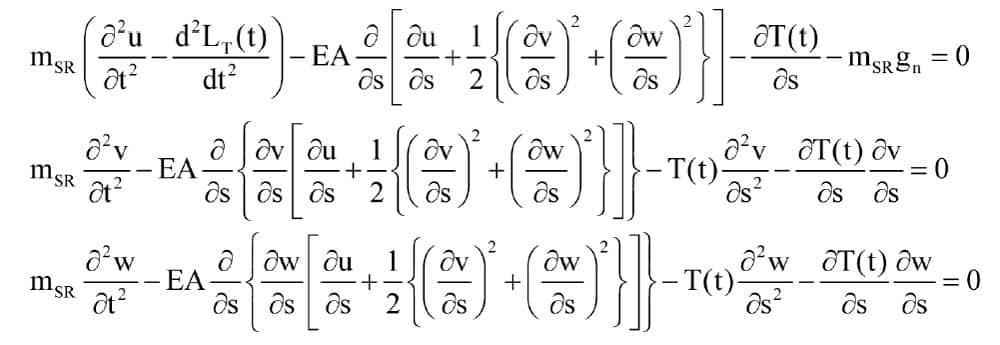
describes the motion of a point on the suspension ropes, while a fourth equation
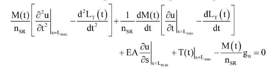
describes the oscillating motion of the elevator car. Note that this final equation is evaluated at the position s = Lmax, i.e., at the mean position where the suspension meets the car top. At this position, v = w = 0, since the ropes can-not move laterally where they are attached to the car, so the equation does not include any terms relating to v and w or their derivatives.
While this set of four equations is extremely complex, the point of interest for the elevator engineer is simply that all of the three motions u, v and w appear in each differential equation of the set describing the rope oscillations. This indicates that the three motions are coupled one to the other and will interact. Thus, a lateral oscillation of the ropes can generate a longitudinal oscillation and vice-versa, and any and all of the modes of oscillation will lead to oscillations of the elevator car.
It’s fairly clear that at any instant, the mean tension at any point in the suspension rope will be
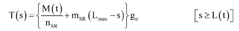
Note that since we are assuming that the ropes are oscillating, this is the mean tension. The actual instantaneous tension will depend on the amplitude and frequency of the oscillations.
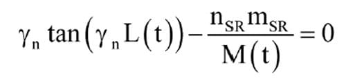
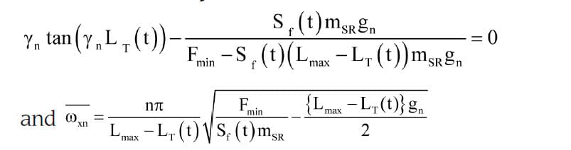
From the set of differential equations above, the natural frequencies of the longitudinal oscillations can be deter-mined from the equation
where Yn are the solutions of
and L(t) = Lmax – LT(t) (Figure 4)
Thus, in this more detailed analysis of the rope oscilla-tion, we find that, contrary to the simplistic prediction of Equation 1, there are possible (and likely) “harmonics” of the longitudinal natural frequency of oscillation of the ropes.
Based on the “slowly varying” criterion, we can use Equation 5 to account for lateral oscillations at any point in the hoistway:
As we did earlier, we can substitute in Equations 13 and 14 from the relation
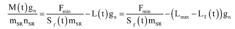
treating the variation of suspended mass over time as a variation in the safety factor, i.e.
thereby expressing the frequency equations in terms of the rope characteristics.
There is a number of possibilities for the excitation of oscillations in the ropes:
- The excitation may be generated from the machine and/or control system through:
- Sheave/pulley eccentricity
- Cyclic phenomena in a speed-reduction unit (e.g., number of starts on a worm shaft)
- Electromagnetic phenomena in the motor (asymmetrical rotor windings in DC machines, spurious conducting paths in the rotor construction, e.g., uninsulated core bolts)
- Frequency instability in the motor drive
- Eccentric roller guide shoes
- Impulsive input from one or more guide joints
- Guide misalignment
- It may occur that one or more of the longitudinal resonant frequencies predicted by Equation 12 coincides with a lateral frequency predicted by Equation 14.
- The building itself may have resonant frequencies coincident with one or more of the frequencies predicted by Equation 12 and/or Equation 14.
Example
Consider an elevator with the following parameters:
- Car-side fixed mass P 1600 kg
- Rated load Q 1250 kg
- Reeving factor r 2:1
Suspension-rope length
- with car at lowest position L0 60 m
- Number of suspension ropes nR 6
- Number of compensation ropes nCR 4
- Number of traveling cables nTC 3
- Suspension rope mass/m mR 1.2 kg/m
- Compensation rope mass/m mCR 1.6 kg/m
- Traveling cable mass/m mTrav 0.5 kg/m
Suppose that the rated speed is 3.5 mps and that the traction sheave has a diameter of 560 mm but is slightly eccentric, generating a longitudinal disturbance to the suspension ropes at a frequency of approximately 4 Hz when the elevator is running at rated speed. The first four calculated longitudinal natural frequencies of the suspension ropes X ꙍ0u , ꙍ2u, ꙍ3u and ꙍ4u) are shown in Figure 5 plotted against the suspension-rope length.
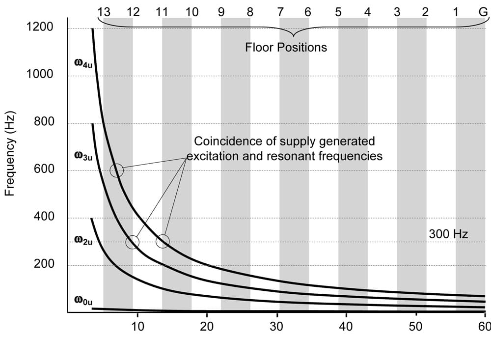
Superimposed on the plot are shaded areas indicating the floor positions of the building. Each floor position is located at the boundary of a shaded area as shown. It is clear from the diagram that the fundamental longitudinal frequency (ꙍ4u) is quite low, as might be predicted from experience.
However, when we look at the second, third and fourth resonant frequencies, we see quite clearly how these increase as the elevator approaches the highest position. In a motor drive linked to mains frequency (e.g., a variable-voltage DC drive), it is likely that there will be a certain level of excitation generated by the drive at either 300 Hz or 600 Hz (based on a 50-Hz supply) or 360 Hz or 720 Hz (based on a 60-Hz supply). Clearly, at a number of locations between the 11th and 13th floors, any such excitation will coincide with one of the natural frequencies of the suspension and may well generate an associated vibration in the elevator car – a phenomenon of transient vibration as the elevator approaches the upper floors, which is well observed in practice, as we indicated in Figure 1.
If we now consider the lateral frequencies (Figure 6), superimposed on the diagram is the variation in the fundamental (lowest) longitudinal natural frequency (dotted line). The horizontal (double The nine points where there is a coincidence between the pulley frequency and one of the natural frequencies are indicated by circles, starting with a coincidence located between the first and second floors where the longitudinal frequency coincides. This low frequency might be significant in that it could possibly excite a natural frequency of the compensation ropes, initiating rope sway beneath the car or oscillation of the compensator mass.
Of particular interest is the coincidence between the second harmonic of the sheave frequency, the longitudinal fundamental frequency and the fourth lateral frequency at approximately 7.5 Hz just above the 11th floor, with an additional coincidence between the second lateral frequency and the fundamental pulley frequency at around 4 Hz at almost the same position. There is a further coincidence of resonances as the elevator runs into the top floor. It could be predicted that this elevator might have some serious vibration problems, particularly around the 11th floor.
Summary
Transient vibrations at certain locations within the elevator hoistway are a well-recognized phenomenon. Bydotted) lines show the location of the fundamental frequency and second harmonic frequency of the eccentric pulley.
considering the elevator suspension as a slowly varying system, the dynamic equations for lateral and longitudinal displacements can be established by the application of Hamilton’s Principle, which suggests that the variation in the time integral of the difference between the kinetic energy and the potential energy of the system is stationary over time, i.e.,
The set of nonlinear differential equations that results from the analysis clearly indicates that there is cross cou-pling between longitudinal and lateral oscillations in the ropes. Consequently, if, at some location in the hoistway, the longitudinal and lateral natural frequencies coincide, there is the likelihood that this cross coupling will excite a transient vibration in the car. The numerical example demonstrates that there is the potential for transient oscillations at several locations in the hoistway, particularly near the upper floors, where external forcing influences such as minor sheave eccentricity may coincide with one or more of the natural frequencies of the system.
While it is useful to explain the source of such transient vibrations and to be able to predict where and how they might arise, a practical engineer will question what pal-liative or curative measures can be taken to reduce or eliminate the effect. Experience demonstrates that this is far from a simple matter. The resonant frequencies are a function of the rope tension and rope length, which makes it quite difficult to move the resonance out of the way, since these parameters are fundamental to the elevator installation. Increasing the mass of the elevator would lower the resonant frequencies, but that would probably mean that the resonance simply moved to a location further up the hoistway. It would be fortuitous if it were possible to lower the resonant frequencies sufficiently to move the location of the resonance beyond the highest point in the travel.
The major contribution to the problem arises from the rope characteristics. As we noted at the beginning of the discussion, conventional steel wire-rope construction provides a suspension member with very little damping, i.e., once the vibration has been started, there is not much in the rope construction to absorb or dissipate the vibration energy. It is the absorption/dissipation of the vibration energy that is key to alleviating rope transmit-ted vibrations. New rope materials such as Kevlar® have better damping characteristics and should be less prone to the problem. However, these types of rope do not (yet) find universal application, and while they are becoming more common, extensive service experience such as is available with traditional steel wire ropes has not yet been built up.
Several authors have proposed a range of methods for damping out rope sway in compensation and suspension ropes. [1,3 & 6] Robertson[3], Barker[4] and Traktovenko[5] have patented mechanical methods to restrain the amplitude of rope oscillation at one or more points between the elevator car and the end of the hoistway. Salmon and Hiller[6] patented a hydraulic tie-down system for the compensator to minimize sway in the compensation ropes.
It is conceivable that an intelligent, active anchorage on the elevator car might be used to isolate the car from any oscillation in the suspension ropes, but such a system would be complex. Bearing in mind that the rope anchorage is fundamental to the integrity of the suspension, the safety implications of such an approach would also need considerable investigation and might have difficulty in the context of the essential safety requirements inherent in elevator safety codes.
References
[1] Kaczmarczyk, S., (1997) The Passage Through Resonance in a Catenary-Vertical Cable Hoisting System with Slowly Varying Length, Journal of Sound and Vibration, Vol. 208 (2), pp. 243-269
[2] Sun, L., (1995) Building Sway and Elevator Rope Vibration, Parts I, II, and III. ELEVATOR WORLD, Vol. XLIII, No. 3, 4 and 5
[3] Robertson, L.E., (1992) Sway Minimization System for Elevator Cables, U.S. Patent 5,103,937
[4] Barker, F.H., (1999) System and Method for Minimizing Horizontal Vibration Elevator Compensating Ropes, U.S. Patent 5,861,084
[5] Traktovenko, B. G., Erlandson, P. O., (1999) Swing Arm to Prevent Sway of Elevator Ropes, U.S. Patent 5,947,232
[6] Salmon, K. J., Hiller, I. A., (1985) Hydraulic Tie Down for Elevators, U.S. Patent 4,522,285
Get more of Elevator World. Sign up for our free e-newsletter.


