Ropes and Traction
Oct 1, 2019


Value: 1 contact hour (0.1 CEU)
This article is approved for Continuing Education by NAEC for CET® and CAT®.
EW Continuing Education is currently approved in the following states: AL, AR, FL, GA, IL, IN, KY, MD, MO, MS, MT, OK, PA, VA, VT, WV and WI. Please check for specific course verification of approval at Elevator Books.
Learning Objectives
After reading this article, you should have learned about:
- An introduction to different roping systems
- The basic structure of typical steel wire ropes and the reason they are used in an electric elevator system
- The terminology of elevator hoist ropes
- The desirable requirements of steel wire ropes
- The importance of rope lubrication and its implication on rope life
An introduction to hoist ropes
This article is excerpted from your author’s book, The Elevator: From Basics to Calculus, which discusses key elements in elevator systems, focusing on the topics of motor drives and control, traffic analysis, and ropes and traction. It is intended to provide quick reference for experienced professionals and basic knowledge of elevator systems for those new to the industry…….. Editor
There are basically two main types of elevators in the world: traction (called “electrical” in the U.S.) and hydraulic, notwithstanding the minor types like drum drives, linear-motor drives, pneumatic (vacuum) drives, etc. More than 99% of elevators operating in the world are of the traction type — in particular, those with a rated speed of 1 m/s (200 ft/min) or above. These elevators rely on hoist ropes to ascend and descend. Furthermore, the effective operation of the ultimate safety device of an elevator (i.e., speed governor and safety gear), heavily relies on the governor rope, though a bit thinner as compared with that of the hoist or suspension ropes. That indicates the importance of ropes in an elevator system. However, the hoist rope is also a key troublemaker in elevator accidents.
Good maintenance and inspection of ropes demand a skillful job not easily achieved by laymen. And, there is no specific life expectancy of hoist ropes, though we can perform an estimation based on usage, environment and maintenance. Here, we are going to look at different types of roping systems, types of hoist ropes and their structure and routine maintenance. Many articles on this topic can be found in ELEVATOR WORLD, such as: Wolf, E. and Franz, A., “Wire Rope – Rope Development for Elevators,” (March 2006, p. 122-126); Rhiner, M. and Heling, K., “Understanding Elevator Rope, Performance, Endurance and Longevity” (April 2009, p. 95-101); and Scheunemann, W., Vogel, W. and Barthel, T., “Steel Wire Ropes for Traction Elevators” parts one (May 2009, p. 87-92), two ( July 2009, p. 63-73) and three (September 2009, p. 95-112).
Types of Roping Systems
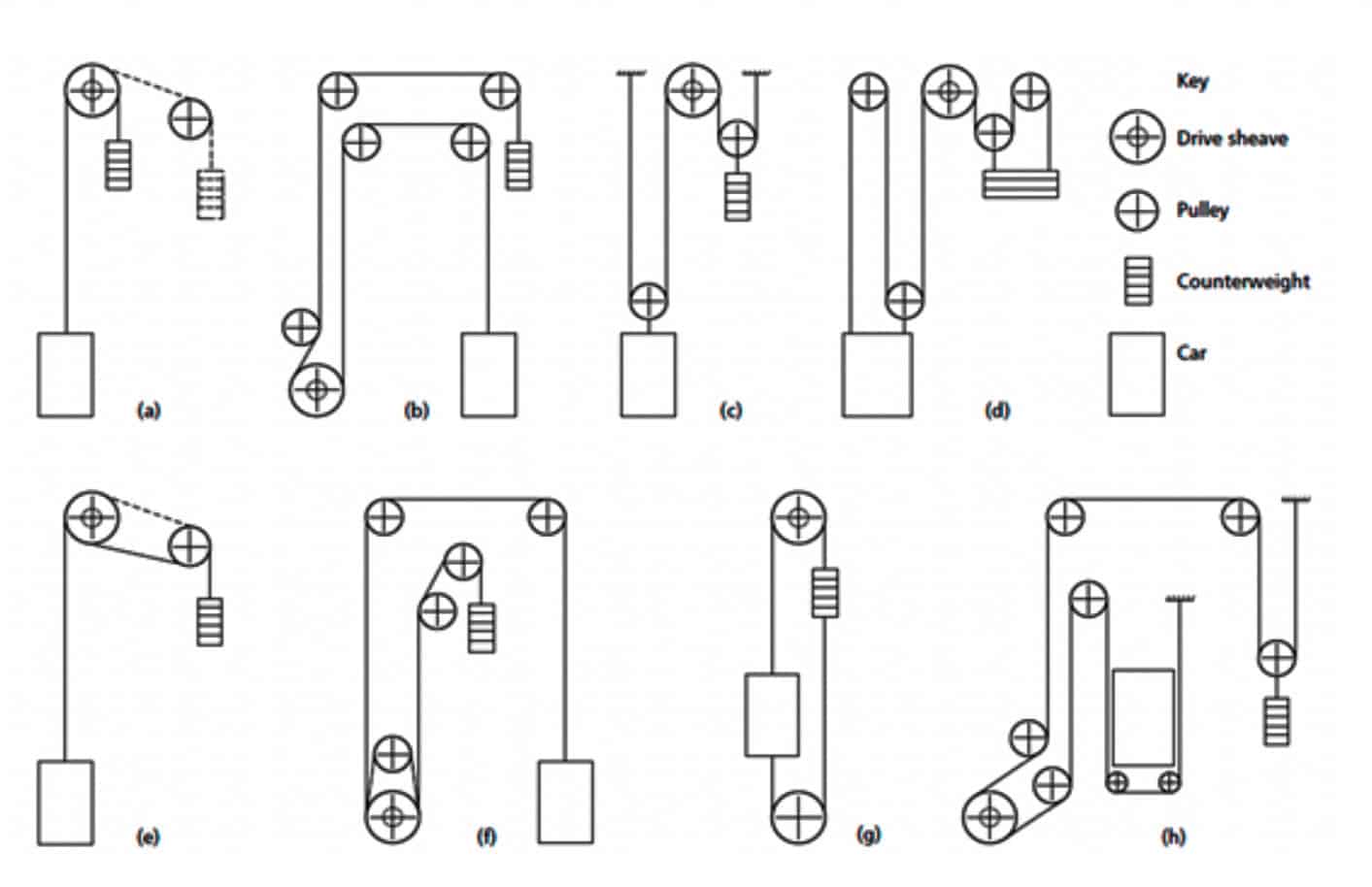
There are many types of roping systems (Figure 1). Types (a), (b), (c) and (e) are most common. The most popular type that can explain the operation of a typical traction elevator is type (a), usually for high-speed elevators. Hoist ropes are connected to an elevator car (cab) at one end and to a counterweight at the other end. Ropes are laid over grooves on the drive sheave, which is driven by a motor via a brake with or without a gearbox. The frictional force between the grooves and ropes drives the ropes up and down. The counterweight is usually adjusted to be the weight of the empty car, plus half the full load capacity. In other words, when the car is half-loaded and in the middle of the hoistway, the whole system becomes stationary, even if the brake is released. The pulley of type (a) is called a “diverter pulley,” which is used to keep an appropriate distance between the car and counterweight. Otherwise, they would easily hit each other when moving up and down along the shaft.
Type (a) is a single-wrap drive with a roping factor of 1. It is usually used for high-speed elevators with a speed equal to the rotating speed of the drive sheave in rad/s multiplied by the radius of the sheave. The main advantage of a single-wrap drive is its high-speed operation, but the motor power needs to be higher, because power is equal to the multiplication of rotating speed and torque. Torque is the twisting force that tends to cause rotation. In physics, it is equal to the force applied, multiplied by the perpendicular distance between the force and axis of rotation. For the same power rating, higher rotating speed means lower torque.
A roping factor of 2 is often used, as shown in type (c), to increase the lifting capacity of the system. This type is still a single-wrap drive. When stationary, the weight of the car and load is equal to double the tension of all hoist ropes. But, of course, something must be sacrificed here, as the rated speed of the elevator car is also halved. Readers may be familiar with the concepts of mechanical advantage (MA) and velocity ratio (VR) of machines. MA is defined as the ratio of the force produced by a machine to the force applied to it. VR is defined as the distance traveled by the effort applied to the machine to the distance traveled by the load. Efficiency of the machine, always below one, is equal to MA divided by VR. It should be noted that the torque of the drive sheave is transmitted to the hoist ropes via the frictional force, called “traction,” between the grooves and ropes. To enhance the traction, double-wrap drives are often used, as shown by type (e). All these types have the electric machine in an overhead position.
If it is not feasible to provide a machine room above the top floor (e.g., due to lack of space above the top floor), types with the machine in the basement position are sometimes used. These are illustrated as types (b), (f ) and (h).
Structure of a Standard Steel Wire Rope
Usually, hoist ropes are made of steel. A rope is not a solid object; it consists of strands made up of small steel wires with a core made of either fiber (natural or artificial) or steel (Figure 2). This is because ropes need to bend around the curved grooved surface of the drive sheave and pulleys, go straight and bend repeatedly under high speeds. That means a rope continues changing its shape during normal operation. It is impossible to accomplish this task by using one solid piece.
As shown in Figure 3(a), if the rope is a solid object, it will break when passing over a sheave. The use of strands is unavoidable.Since the rope has thickness, when going over a curved surface, its outer bend must be extended, while the inner bend is shortened, when passing over a sheave. This is impossible if a parallel wire bundle is adopted.
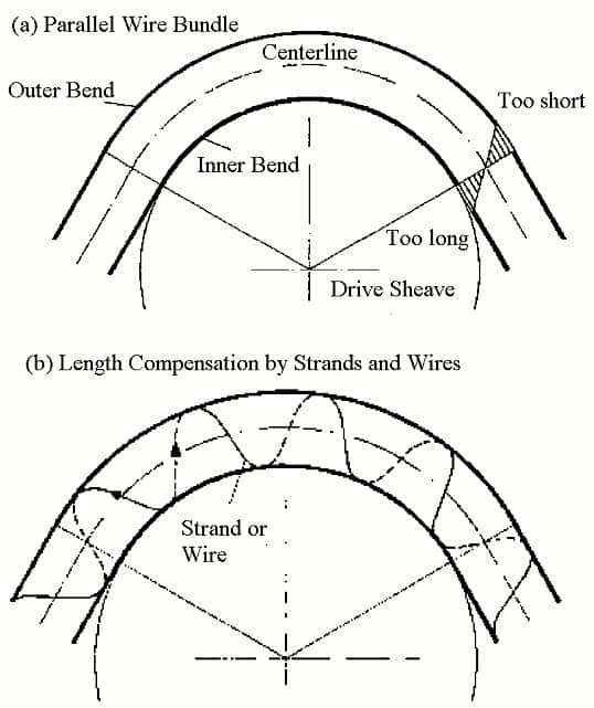
Therefore, as shown in Figure 3(b), length compensation must be manipulated so that the total length of every piece of wire (or, every strand) can remain unchanged during bending. This is done by using a twisted form, in which strands are allowed to shift marginally in a spiral manner. In this way, during normal operation, every piece of wire and every strand is rubbing against another. Strands rub against each other at the valleys and rub against the groove of the drive sheave at the crowns. This explains why rope lubrication is of utmost importance. Proper lubrication ensures wires do not break when rubbing against each other or the grooves of the drive sheave, while not reducing the friction between the wires and grooves. Because of this, a special lubricant (as specified by the rope manufacturer) is to be used during routine maintenance.
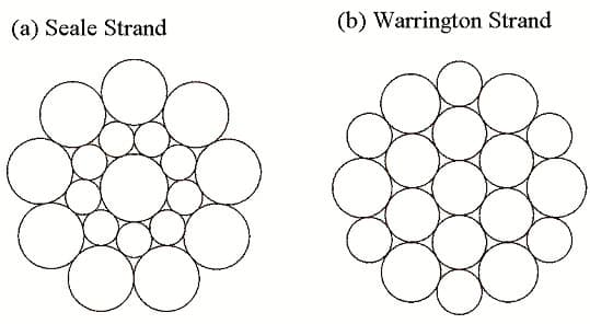
In elevator systems, the parallel-lay strands are often employed where no two pieces of wire cross each other. The number of strands and wires varies between different types of ropes. Usually, there are 19 pieces of wires on one strand, arranged in two major ways: Seale and Warrington. Their cross-sections are shown in Figure 4, which also shows both types typically have three layers of wires (i.e., 9 + 9 + 1 = 19 for Seale and 6 [outer layer] + 6 [outer layer] + 6 [inner layer] + 1 = 19 for Warrington). The 12 wires on the outer layer of the Warrington arrangement are of two different sizes. That is to make the rope look more circular. Another arrangement, Warrington-Seale, has more wires on one strand. There are typically six strands per rope for low-speed operation and eight strands per rope for high-speed operation.
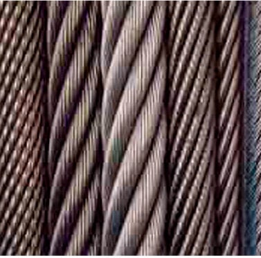
There are right-handed-lay and left-handed-lay ropes. Elevator ropes are usually right-handed-lay (Figure 5), by which the strands, when moving along the rope as seen by the holder at one end, are rotated clockwise. Furthermore, there are two types of lay: ordinary (or regular) lay versus Lang’s lay. The latter has a different lay direction for the outer strands in the rope from the wires in the outer strands (compared to that of ordinary lay, as shown in Figure 5). Therefore, in regular-lay ropes, the visible outer wires follow the approximate direction of the rope axis. In Lang’s-lay ropes, the visible outer wires are inclined at a steep angle to the rope axis. Elevator ropes are usually of an ordinary lay. It is easier to mount ordinary-lay ropes, which only have a slight tendency to untwist when being hung freely in the elevator shaft. Their elastic elongation is lower than that of Lang’s-lay ropes.

The six or eight strands of wires are supported, or spaced outward, by the core of the rope (Figure 6). This is a main function of the core: without it, strands cannot be properly spaced to form a relatively round rope. Another main function of the core is that it acts like a storage pool for lubricant.
Cores of natural fiber are usually made of sisal or hemp, which has a good absorption power for lubricant and low longitudinal elastic elongation. However, natural fiber is sensitive to high air moisture, and it easily gets rotten when exposed to moisture. So, ropes with natural fiber cores are not suitable to be used in shafts with high humidity. Synthetic fiber has a relatively lower absorption power of lubricant and higher longitudinal elastic elongation. It is suitable for use under a humid environment.
Steel wire is usually used in ropes with metallic cores. This type of core increases the metallic cross-section and reduces tensile stress in individual wires. They are subject to lower elongation under the same load condition as ropes with a fiber core. However, ropes with a steel-wire core are not permitted to rotate during installation. (In ropes with fiber cores, all strands become evenly longer or shorter when the rope rotates.) In ropes with steel wire cores, both outer and inner strands loosen to a certain degree. Therefore, this type demands higher skill for installation.
Tensile Stress and Elongation
Since the strands run in a spiral, they, being metallic, act like springs. Under load, a hoist rope extends like a spring and returns to the original length when unloaded. Hence, Hooke’s Law applies. Young’s modulus, or the modulus of elasticity, E(ε), is defined as the ratio of the tensile stress σ(ε) to the elongation ε. The following set of equations is valid:

Here, F is the force exerted on the rope under tension, A0 is the actual cross-sectional area through which the force is applied, ΔL or x is the elongation or the amount by which the length of the rope changes, and L0 is the original length of the rope. k is called “Hooke’s constant,” which describes the stiffness of the rope based on the model of a spring. Ropes of low longitudinal elastic elongation have a larger value of k.
Requirements of Hoist Ropes
Ropes made of steel wire, as opposed to other materials, are used in elevator systems for several reasons. Obviously, the tension must be adequate, as a fully loaded car is very heavy.
Furthermore, under acceleration, the weight could be 15% more because the normal acceleration rate is around 1 m/s2 (200 ft/ min2, or 10% of gravity) and, sometimes, even higher. Besides tension, ropes are exposed to other stress factors, including flexural stress, when wires bend in relation to each other; torsion, where it is unavoidable that ropes are twisted under operation; friction, resulting in additional abrasive wear of the strands; and compression, when ropes are passing sheaves and pulleys.
Since ropes are used to lift the elevator car or counterweight (they always travel in opposite directions) due to the friction between the grooves on the drive sheave and ropes, traction is the first consideration. While the traction must be sufficient, it cannot be excessive. The code specifies that when the counterweight sits on the buffer in the pit, the traction must not be so high that it lifts a car above the top floor, even if the drive sheave is still rotating.
Usually, there are several ropes for one elevator car. Such active redundancy is provided to make sure that when one rope fails, the whole system is still safe, because the remaining ropes can take over the role of this failing rope. The elevator car must still be suspended safely when only one rope remains intact. This is called “factor of safety,” which must be at least 12 in Europe and about 10 in the U.S., under a rated speed of 2 m/s or 400 ft/min. The factor of safety of ropes is defined by the ratio of minimum breaking strength of one rope to its own operating tension.
There is one more advantage to using steel wire ropes: the capacity for maintenance personnel to identify the possibility of the end of its service life. The assessment is generally based on measuring the diameter of a used rope, the number of wire breakages on the outer layers of the strands, the existence of rouge (red powder on the surface of the rope suggesting that advanced deterioration is taking place), etc. The measurement of rope diameter must be crown-to-crown. Two measurements 90° apart must be done to arrive at an average value, because an operating rope is very often not perfectly round.
Ideal properties of ropes include:
- Smallest possible degree of rope wear, demanding thick wires and high wire tensile strength
- Long rope life when running over sheaves and pulleys, demanding thin wires (So, a compromise must be made when considering the above point. This conflict is also present in the next two points.)
- Compatibility with the drive sheave, demanding low wire tensile strength
- Highest possible breaking strength, demanding high wire tensile strength
- Low rope elongation due to rope shortening processes after operation for some time and ride comfort expectations, demanding a high metallic cross-sectional area and top-quality fiber core
- Affordability
Different requirements may end up with differences in desirable rope structure. As can be seen, there is often a fundamental conflict between them. So, a good compromise is always needed based on actual operating conditions.
Tensile strength, an important parameter of a steel wire rope, indicates the maximum load a rope can normally take. Wires with high tensile strength are usually harder. Of course, when a rope is subject to wear and tear and metallic fatigue, the tensile strength will gradually diminish. The tensile strength of wires at the inner layers of the strand (typically 1,770 N/mm2) is often different from that at the outer layer of the strand (typically 1,370 N/mm2). This is called “dual tensile” because the hardness of a rope is usually higher than that of the groove of the drive sheave. A softer outer layer of wires of a strand, with a relatively lower tensile strength, can reduce the wear on the groove to a minimum.
Rope hardness is usually higher than 400 HB on the Brinell scale, while groove hardness is slightly higher than 210 HB. BHN is designated by the most commonly used test standards (ASTM E10-14 and ISO 6506–1:2005) in terms of “HBW” (“H” from hardness, “B” from Brinell and “W” from the material of the indenter, tungsten [wolfram] carbide). In former standards, “HB” or “HBS” were used to refer to measurements made with steel indenters. HBW is calculated in both standards using metric units as:

where F = applied load (in Newtons), D = diameter of indenter (in millimeters), and d = diameter of indentation (in millimeters).
The HBW value of 1,770 N/mm2 is popularly used around the world. For the inner wires, 1,180 N/mm2 or 1,570 N/mm2 are also used. For an 8 (strands) X 19 (wires per strand) rope with tensile strength (1,370/1,770) with a diameter of 11 mm (7/16 in.), the maximum breaking strength is 55.7 kN (12,500 lbf ). If wires of a tensile strength of 1,770 N/mm2 are used throughout the whole rope, in difference between inner wires and outer wires of a strand, the maximum breaking strength becomes 62.8 kN (14,100 lbf ). If these ropes are used for an elevator with a rated speed of 2 m/s (400 ft/min), the maximum tension under a static condition in any one rope must not be more than 6.3 kN, as a safety factor of 10 applies in the U.S.

As stated before, rope diameter must be measured crown-to- crown (Figure 7). For traction or electric elevators, when newly installed, the rope diameter must be between 0% and +5% of the nominal diameter. When old, the diameter could drop to -6% to -10%, and it must be discarded.
Lubrication of Hoist Ropes
As mentioned before, during normal operation of ropes, the wires keep rubbing against each other and against the grooves of the drive sheaves and pulleys. The only reason ropes can bend over sheaves or pulleys is that all wires are capable of displacement relative to one another. Therefore, rope lubrication is necessary. Such lubrication reduces friction between wires and between strands. However, at the same time, it must not reduce the traction between the ropes and grooves. This concern means it is false to assume the concept of “the more, the better.”
As mentioned before, the fiber core of a rope is a storage pool of lubricant. When delivered from the manufacturer, the new fiber core of any rope is well soaked with lubricant, while the rope itself is well lubricated. Once the rope is installed and brought into operation, lubricant from the fiber core is forced to seep outward. Therefore, after a few weeks of operation, it is necessary to clean the lubricant on the rope surface. Relubrication is then needed. From that point onward, ropes must be continuously checked for a lack of lubricant. Relubrication will be necessary from time to time — for example, a couple times a year. The reapplication of lubricant must depend on the condition of the rope, as the frequency of relubrication depends on several factors:
- Frequency of elevator operation
- Environment of operation (including temperature, humidity, presence of dust, etc.)
- Sheave material and sheave wear
- Hardened traction sheave (which will need more frequent relubrication)
- Slippage between the ropes and drive sheave
Before relubrication is conducted, thorough cleaning of therope surface is necessary. This is because, during operation, the lubricant is often mixed with dust and dirt in the elevator shaft and machine room. Such contaminated lubricant must be removed before any new lubricant is added. Lubricant must be clean and not contaminated with external dirt. Otherwise, there is no way to check the rope diameter accurately and count the number of wire breaks to determine the life of the rope.
Relubrication also serves one important purpose: to keep the fiber core its original size. As the fiber core’s main mission is to keep the strands in position, when the core is well-lubricated, strands are properly spaced, and they do not rub against each other too hard. However, the fiber core shrinks and gets drier if it gradually loses lubricant. Under this situation, it is less effective at spacing out the strands. Since all strands are under high tension, they try to move toward the core as the core becomes thinner. During operation, strands and wires rub against each other harder and harder.
There are two problems here. First, the whole rope becomes a bit thinner, reducing the contact surface area between the rope and groove and affecting traction. Second, more significantly, the surface of the wires is under huge wear. Iron particles form on the rope surface. As these particles are no longer protected by the lubricant, they tend to form rust quickly by oxidation. That results in the formation of red dust on the rope surface, called rouge. As iron particles are removed from the wires, wires get thinner and are easily prone to breaking under abrasion.
It is obvious that every piece of wire in every strand is under tension, as all the wires share the load of a rope. As the wire becomes thinner, even though the tensile strength remains unchanged, the maximum load the rope can take is reduced, as the area of wires gets smaller. Hence, when maintenance personnel find rouge on a limited portion of the rope surface, the rope must be maintained immediately, though replacement may not be urgent. Maintenance of a rope with rouge cannot bring the rope to the state it was in when new, but it can at least reduce the rate of deterioration. When a rope is covered with rouge, even along a small portion, and left unattended, it will deteriorate quickly, and the life is very much shortened.
Some manufacturers claim their ropes do not need relubrication, because the lubricant added during manufacturing is good enough for the life of the rope. This claim is very doubtful, because there is no determined life of a rope. It can be short or long, depending on the operating conditions and environment.
To play it safe, ropes must be regularly cleaned and relubricated to prevent fast deterioration.
Learning-Reinforcement Questions
Use the below learning-reinforcement questions to study for the Continuing Education Assessment Exam available online at Elevator Books or on p. 141 of this issue.
- Why are strands and wires used to make hoist ropes?
- Why is steel used to make hoist ropes?
- Why is a diverter pulley always necessary?
- Which factors determine whether a rope should be discarded?
- What is “active redundancy” of a roping system?
- Compare the pros and cons of 1:1, 2:1 and double-wrap roping systems.
- Why does a rope need lubrication and relubrication?
- Why is the tensile strength of wires on the outer layer of a strand different from that on the inner layers of a strand?
- Why must attention be paid to the existence of rouge on ropes?

Get more of Elevator World. Sign up for our free e-newsletter.