Simulation Solves Elevator Accident Mystery
Sep 1, 2015
Multiphysics simulation is used to investigate and determine how an elevator brake failed prematurely.
by Dr. Stuart Brown, Dr. Nagi Elabbasi and Dr. Matthew Hancock
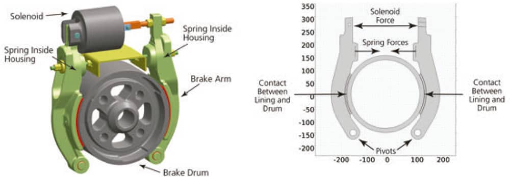
In 2007, an elevator began moving upward while passengers were exiting, trapping and injuring an occupant. A drum brake intended to hold the elevator stationary failed, resulting in the unexpected movement. Subsequent investigation revealed that a solenoid responsible for opening and closing the brake had deteriorated, causing the brake linings to drag on the drum and wear prematurely. When the solenoid was not engaged, normal brake shoes would have pushed against the drum, preventing elevator motion. Excess brake-shoe wear caused the brake to fail to hold, leading to the accident. Figure 1 shows a computer-aided-design (CAD) model of the brake, in which its arms are pivoted at the bottom and spring loaded to maintain contact with the drum.
Criminal charges were filed against the elevator maintenance firms, claiming that there was evidence in previous years that the solenoid was deteriorating and that repairs should have been performed. The question was not whether the solenoid had failed, but, rather, how did it fail and at what rate?
If the failure were rapid, it would have been unlikely that the accident could have been anticipated. However, if the failure involved a slow deterioration, perhaps the accident could have been prevented. Many possible theories of failure were suggested. Veryst Engineering was hired to investigate the validity of the different failure theories, and simulation played a pivotal role in our investigation.
Analysis of Solenoid Failure
After the accident, investigators discovered that the solenoid had approximately half the electrical resistance of an undamaged solenoid, and, therefore, generated less force compared to an undamaged solenoid. Several theories were proposed to explain how this failure could have occurred.
One theory for slow failure was that thermal expansion and contraction within the solenoid due to resistive heating produced high stresses leading to slow, progressive cracking of the wires within the solenoid coil. Cracks would reduce the solenoid’s electromotive force (EMF), thereby leading to brake-shoe dragging. To test this theory, we used the COMSOL Multiphysics® software to produce a coupled thermomechanical stress analysis of the solenoid. The model demonstrated that the stresses were not large enough to produce cracking, therefore proving that expansion and contraction due to resistive heating was not the cause of the failure.
A second theory for slow failure was that the EMF itself generated high stresses in the coil, causing it to fail over an extended period of time. We tested this by performing a coupled electromechanical analysis (Figure 2). The simulation software was used to calculate the Lorentz force within the solenoid coil, demonstrating that the force throughout the coil was practically negligible.
In contrast, one theory for rapid solenoid failure stipulated that localized heating within the solenoid resulted in shorting between adjacent coil wires. While we did not analyze this theory directly, our analysis refuting the above slow-failure theories narrowed the field of possible failure modes and lent support to the rapid failure scenario.
Analysis of Rapid Brake-Lining Wear
In addition to the solenoid failure analysis, we investigated the effect of a damaged solenoid on brake-lining wear. Given that the solenoid involved in the accident could not generate the force of a normal solenoid, could the brake linings have also deteriorated so quickly? After the accident, investigators discovered that the brake-lining wear was extensive and assumed that this degree of wear had to have occurred gradually.
To test whether the extensive brake wear could have occurred swiftly given a damaged solenoid, we developed a computer-based model of the brake to calculate the local brake-lining wear. The model included the brake arm pivoting, as well as the opposing forces of the springs and damaged solenoid. In addition, the model included data from the extensive-wear experiments performed by investigators on prototype drum-brake linings, which resulted in data correlating bulk lining wear rates to brake-drum temperature.
We used this temperature-wear data combined with a wear rate model commonly used in the brake industry to develop a local wear-rate model. The model was implemented using both the Structural Mechanics Module and user-defined differential equations defined on the brake-lining surfaces. The contact-boundary condition available in the simulation software provided the local contact pressure for the model, which was used to determine the local wear rate at each point along the brake linings. The predicted brake-lining wear was, in turn, used to specify an offset from the original brake surface in the contact-boundary condition, a valid assumption provided the amount of wear is small compared to the lining thickness. The input to the wear simulation was an assumed time history of drum temperature. We validated this wear-modeling approach by simulating two mechanical wear problems: wear resulting from pin-on-disc contact and wear in automotive disk brakes.
The contact boundary condition within the Structural Mechanics Module of the software and the ability to easily implement user-defined differential equations made programming the wear process straightforward and helped us avoid cumbersome methods, such as mesh element deletion. This type of analysis would have been either impossible or prohibitively difficult using any other finite element package.
Figure 3 shows the finite element model used in the wear analysis. Figure 4 shows a comparison between the measured and predicted brake lining wear along the length of the brakes at the end of the test. The model also predicted how wear depth varied with time. The results of the wear simulation indicated that a damaged solenoid could result in high drum temperatures, leading to rapid brake-lining wear.
In other words, the high amount of wear on the brake linings was entirely consistent with a rapid train of events, from the rapid deterioration of the solenoid to the rapid and extensive brake-lining wear. This rapid-failure theory provided an alternative, self-consistent and scientifically sound explanation of the accident, involving no slow processes.
Conclusion
While we can easily picture simulation as an integral part of product design, other uses are equally important. Simulation was an essential contributor to this investigation, enabling us to quickly investigate different scenarios by allowing us to readily import and handle different geometries, include multiple physics in a single simulation, and import and use experimental data with our simulations. The simulations provided an efficient and systematic way to test and evaluate the failure scenarios, an approach no one else had tried.

Figure 1: (l-r) A CAD model of brake geometry; brake lining wear model setup showing the brake drum, arms and pivots; opposing spring and solenoid forces; and contact between brake linings and drum 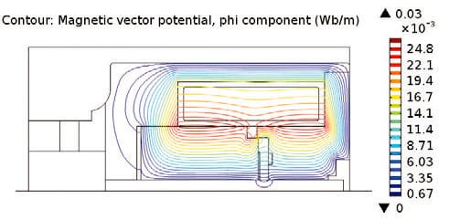
Figure 2: Magnetic potential within solenoid component 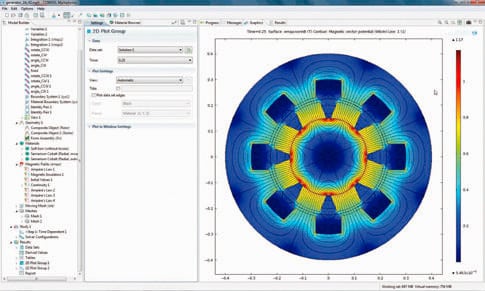
Figure 3: COMSOL Multiphysics® software model used to calculate brake lining wear 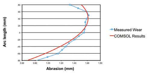
Figure 4: Comparison of measured lining wear with simulation prediction
Get more of Elevator World. Sign up for our free e-newsletter.


