Study on Linear Permanent Magnet Synchronous Machines for Ropeless Lifts
Aug 1, 2024

by Albert So and W.L. Chan
This paper was presented at Elevcon 2023 in Prague, Czech Republic.
Key words: Linear motor, ropeless, permanent magnet, simulation model
Abstract
It is rather certain that multi-dimensional lift systems will soon dominate the lift industry in coming years due to the first successful development of TK Elevator’s (TKE) MULTI™. To facilitate such a design, the concept of ropeless lifts has to be implemented, and the adoption of linear permanent magnet synchronous machines (LPMSMs) such as those used in the MULTI system is an obvious choice. Without the existence of hoisting ropes, lift cars not only can travel along all three directions, but the number of cars in one hoistway is not limited to two. We carried out a series of academic studies to evaluate the performance of such LPMSMs under various conditions by simulation. In this paper, which is a summary of our previous works with some new input, the control method to realize the required kinematics under a full-load up journey, the impact of different electrical parameters on the power consumption, and most importantly, the analytical solution associated with emergency operation under a genuine power failure will be discussed. Machine models of surface-mounted and salient permanent magnets will also be considered. This is basically a review paper based on a series of previous publications of the authors.
1. Introduction
Up to the time that this paper was drafted, the tallest building in the world was still the Burj Khalifa, which is located in Dubai. In the beginning of the 21st century, the Petronas Towers in Kuala Lumpur, Malaysia, were considered “The World’s Tallest” with a height of 452 m. Then in 2004, Taipei 101 in Taipei, Taiwan, became the tallest with a height of 508 m. In 2009, the distinction shifted to Burj Khalifa in Dubai with a height of 828 m. Such records could easily be found on the official website of the Council on Tall Buildings and Urban Habitat (CTBUH), which was formed in 1969.
The next champion may be Jeddah Tower (previously named Kingdom Tower) in Jeddah, Saudi Arabia, although it is still under construction. Initially planned for completion in 2020, the height as originally designed would have been around 1,600 m (almost 1 mi.), thus named the “Mile-High Tower,” informally. The latest information showed that it would only reach 1 km tall, with 167-plus floors. Other existing super-high-rise buildings in the world include the Merdeka 118 in Kuala Lumpur, Malaysia, with a height of 680 m; the Shanghai Tower in Shanghai, China, with a height of 632 m; and the Abraj Al-Bait Towers in Mecca, Saudi Arabia, with a height of 601 m.
Besides these contemporary world records, others at the top of the 2022 “under construction” list may include the Goldin Finance Building in Tianjin, China, with an expected height of 597 m; the Greenland Jinmao International Financial Center in Wuhan, China, with an expected height of 500 m; and the Suzhou Zhongnan Center in Suzhou, China, with an expected height of 500 m. As a matter of fact, most top-ranked “under construction” super-high-rise buildings on the list are in China. It can easily be seen that the world trend in buildings is competing for a new record in terms of height.
Though the official height of the Burj Khalifa is 828 m, the height of the highest occupiable floor within the building is only 586 m, which is equivalent to the 163rd floor. Having said that, this is the exact height to which elevator service is required. It is generally known that traditional elevators are inefficient in serving super-high-rise buildings, as they are time wasting and cost prohibitive. According to IBM (2010), the cumulative time that office workers spend waiting for elevators in the past 12 months (2009-2010) totaled 92 years across 16 metropolitan areas in the U.S. As buildings grow taller, elevators have to serve many more occupants, thus demanding many more elevators and elevator shafts. Ascher (2013) is of the opinion that each additional bank of elevators reduces the floor area available for rent or sale, thus pushing down the revenue potential for the building. Ken Yeang (1996), a renowned architect and ecologist, provides guidelines regarding the ratio of acceptable space in super-high-rise buildings, the net-to-gross floor area being not less than 75%, while a higher figure from 80% to 85% should be better. Subject to the fact that elevators are a size constraint of these super-high-rise buildings, the conventional approach of up to two cars per hoistway should be abandoned. Since traditional elevators for high-rise buildings are rope driven by traction, it is impossible to put too many cars within one hoistway. Furthermore, as the length of hoisting ropes becomes longer, objects may easily reach the resonance level and the vibration of ropes becomes much greater during operation (DOE, 2016) because the natural frequency of a piece of rope is length dependent (Halliday et al., 2015) while such length keeps on changing when the car is moving up and down. Hence, it is very difficult to prevent ropes from reaching their natural frequency (Yang et al., 2017).
The simple conclusion is that elevator cars for such super-high-rise elevators must go ropeless by manipulating linear motor drives. This is not a new idea. As early as 1981, a U.S. patent (US 4402386A) was filed, called “Self-powered elevator using a linear electric motor as counterweight.” Although this system is still roped, the conventional main drive sheave at the top of the hoistway does not exist. The linear induction motor is installed on the cylindrical counterweight that is connected to the elevator car by ropes via pulleys on top of the hoistway (Janovsky, 1993). In other words, the counterweight is powered to lift and lower the elevator car. The first ropeless patent was filed in 1991 (US 5234079A), where permanent magnets are mounted on the side of the elevator car and stator windings are mounted by the side of the guide rails. The permanent magnet rotor of the car is facing the stator windings. When powered, upward thrust can be produced. There is neither rope nor counterweight, thus facilitating as many independent elevator cars as possible in the same vertical hoistway. The magnets are covered with a thin plastic sheet to allow easy removal of iron dust settling on the surface from time to time (Janovsky, 1993).
Linear motors have been in use in other industrial sectors, in particular the magnetic levitation railway system and industrial drives in factories (Boldea et al., 2001; Glatzel et al., 1980; Morizane et al., 2000). In the recent decade, more academic studies of linear-motor-driven multicar elevators have been conducted (Takahashi et al., 2008; Onat, 2010). In their studies, the imperative employment of linear motors to drive ropeless elevators is affirmative. Linear induction motors and switched reluctance motors were considered before, but their ratio of payload to self-weight was relatively low. Hence, the use of LPMSMs was recommended. Furthermore, it was suggested that a major part of the cost was the stator because it had to span the whole hoistway length. Therefore, the air-core PMSM arrangement was adopted with stationary windings along the hoistway, while permanent magnets were installed on the elevator car since it was impractical to attach long electric cables to the mover, which is the elevator car. And the Halbach type of permanent magnet arrangement was adopted to reduce the effect of saliency.
The real implementation of LPMSMs on an elevator system was successful in Germany (Appunn et al., 2018), which is discussed in more detail in the next section.
2. Real Application of LPMSMs on Elevators
2.1 The MULTI™
The tradename MULTI™ first appeared in 2016 (Appunn et al., 2016), when the system was being tested at the TKE test tower in Rottweil, Germany. According to Appunn et al. (2016), a full-scale showcase was installed where commissioning and extensive testing were carried out. By the name MULTI, every hoistway can accommodate as many cars as practical, thus reducing the footprint of hoistways in a super-high-rise building. Each elevator car carries a sledge on the back, which accommodates the secondary permanent magnet yoke of the LPMSM, while the primary part consists of multiple coil units in double array configuration placed along the hoistway(s). All the coils are energized by IGBT-based inverter units as distributed along the hoistways. By double-array configuration, eight motor controllers and coil units act on a single car.
Four exchangers can be located at intersections of the vertical and horizontal rails of the hoistways. The sledge on the back of each car can rotate by 90° at a swivel platform, i.e., the exchanger on the rails. Each exchanger is a direct swivel device that rotates the sledge and the linear motor while the car remains vertical by an interlock. Then, the car can move horizontally until it reaches another exchanger where the sledge can be restored to its vertical direction.
Position sensing of the car is of utmost importance where a special sensor, the mutual effect between the scale on the car and the sensor heads along the hoistway, is utilized. The precision of position sensing is down to micrometers. Each car is equipped with two mechanical braking systems, i.e., the operational brake and the safety gear. According to Appunn et al. (2016), the test run was done with two cars under two scenarios. In scenario one, two cars of different weights were allowed to move up and down together along two independent vertical hoistways with a rated speed of 5 m/s and an acceleration rate of 1.2 m/s2. Here, the peak electric power was consumed, and the effectiveness of the energy buffer was measured and tested. In scenario two, three cars of different weights were moving along both vertical and horizontal hoistways with a vertical speed of 5 m/s and a horizontal speed of 0.2 m/s; the maximum acceleration was 1.2 m/s2 and 0.4 m/s2, respectively.
To facilitate the construction of similar ropeless elevators with the use of LPMSMs, some technologies developed by others may be required, as discussed below.
2.2 Improvement in Thrust of the LPMSM
According to Cui et al. (2020) and Hu et al. (2021), the double-sided LPMSM is a better candidate for ropeless elevators due to the high thrust-density-per-unit length, the cancellation of double-sided normal force and better thrust stability against air gap fluctuation. However, as restrained by the installation accuracy, the air gap of double-sided LPMSMs may deviate during operation, resulting in wear and vibration noise problems. Adjusting the air gap magnetic field of these motors can adjust the normal force (Pang et al., 2021; Cao et al., 2021) so that the air gap returns to the equilibrium position and the influence due to such air gap deviation can be reduced. So, both thrust output and normal force regulations are necessary for double-sided LPMSMs. A suspension-guided LPMSM was developed (Xu et al., 2022) where a salient-pole motor and DC magnetizing motor are integrated together with the addition of a DC excitation winding to the secondary core.
Another approach was the adoption of finite-element analysis to improve the mean force while reducing the force ripples due to saturation by re-arranging the armature coils according to the modified star of slots technique (Souissi et al., 2021).
2.3 Overspeed Governor Design
As mentioned before, the MULTI is equipped with safety gear for emergency purposes. Subject to this actuation, a sensitive overspeed governor is required. The conventional roped overspeed governor is not practical anymore in terms of ropeless elevators. A theoretical and experimental analysis of a new contactless and ropeless speed governor was carried out (Onat A. et al., 2022). By manipulating electromagnetic inductive force to measure the speed of movement of the car, the sensor is mechanically actuated by eddy current forces and its operation is independent of the normal supply of electricity, thus a fail-safe design. Two methods are used to improve sensitivity. First, the eddy current forces are generated through a variable overlapping of a magnet over a reaction plate, making the speed-force relationship non-linear. Second, the eddy current forces are modulated by the speed to obtain mechanical resonance effects.
3. Theoretical Study on LPMSM Applications
3.1 The Machine Model
The machine model of an LPMSM is very similar to that of a rotary one (So et al., 2018), Figure 1. The stationary three-phase windings (1-2-3) to be energized by the IGBT-inverter is first converted to a stationary two-phase system (D-Q) and finally to a rotating two-phase system (d-q) by the famous Clark-Park transformations. This rotating system is chosen to be synchronous with the speed of the rotor.
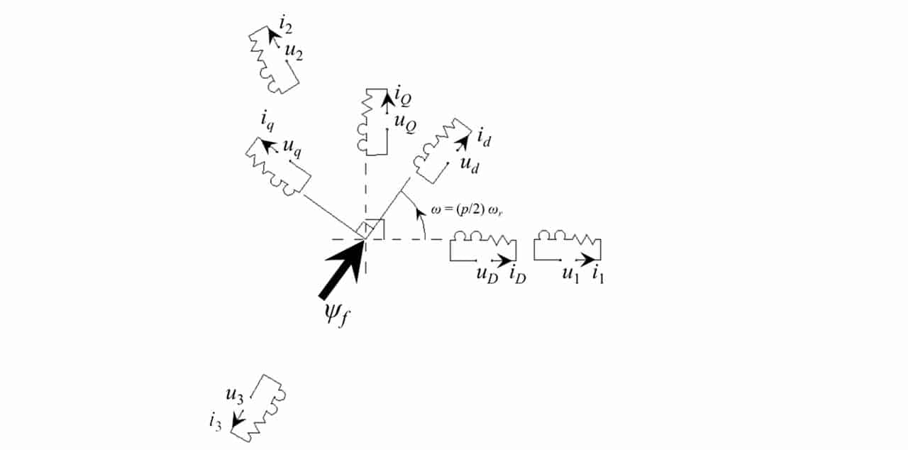
Each winding is represented by equivalent Rs-Ld-Lq series circuits. The instantaneous voltage applied to each winding is denoted by ux, while the current by ix where x = 1, 2, 3, D, Q, d or q. Ψf is the magnetic flux of the permanent magnet on the rotor, i.e., the secondary of a LPMSM.
According to (So et al., 2018), the electromagnetic power, Pem, and the linear electromagnetic force, Fem, of the motor are given by equation 1.
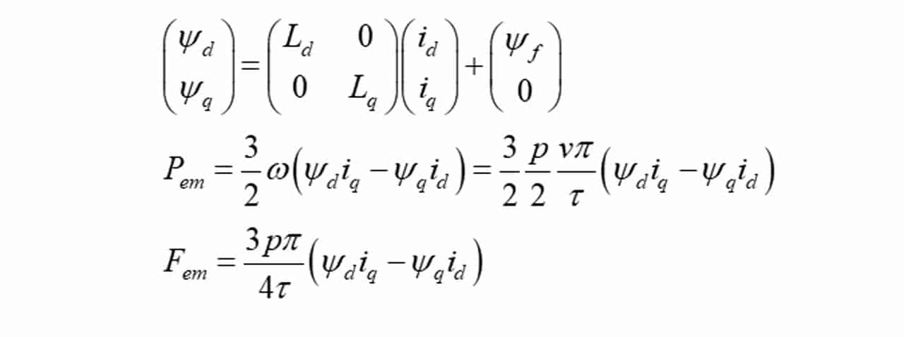
Here, v is the linear speed of the secondary, p the pole number, 𖬘 the pole pitch, Ψd the flux linkage along the d-axis, Ψq the magnetic flux linkage along the q-axis and Ψf the magnetic flux linkage of the permanent magnet, being measured in webers. Ld and Lq are the armature inductances along the d-axis and q-axis, respectively. The secondary, or rotor, has no winding but only a permanent magnet with flux linkage, Ψf along the d-axis and there is no permanent magnet along the q-axis. Hence, total flux linkage along the d-axis, Ψd = Ld id + Ψf and the total flux linkage along the q-axis, Ψq = Lq iq. Let Ψs be the vector sum of Ψd and Ψq, and δ be the angle between Ψs and Ψd, we have equation 2 for the linear thrust. If there is no saliency at the secondary, i.e., uniform air gap between the stator and the rotor, we have Ld = Lq = Ls. Equation 2 then becomes equation 3.
That explains why traditional control of PMSM or LPMSM plays around the current along the q-axis only to determine the right torque or right thrust. From equation 3, it is obvious a larger thrust can be obtained by increasing the current along the q-axis and the natural magnetic flux of the permanent magnet. However, it is costly to install permanent magnets with a high flux.
3.2 Consideration of Energy Consumption
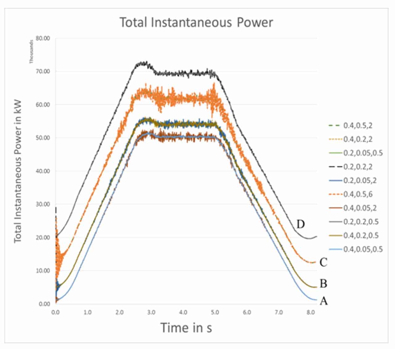
According to So et al. (2018), it was found that the energy consumption of a ropeless elevator based on LPMSM is dependent of Ls (no-saliency was assumed), Rs and Ψf. Table 1 shows motor parameters used to carry out the simulation and the standard kinematics was adopted, i.e., a full load up-journey consisting of seven processes, namely, jerk, acceleration, jerk, rated speed, jerk, deceleration and jerk, respectively.
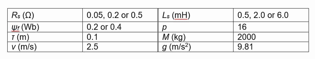
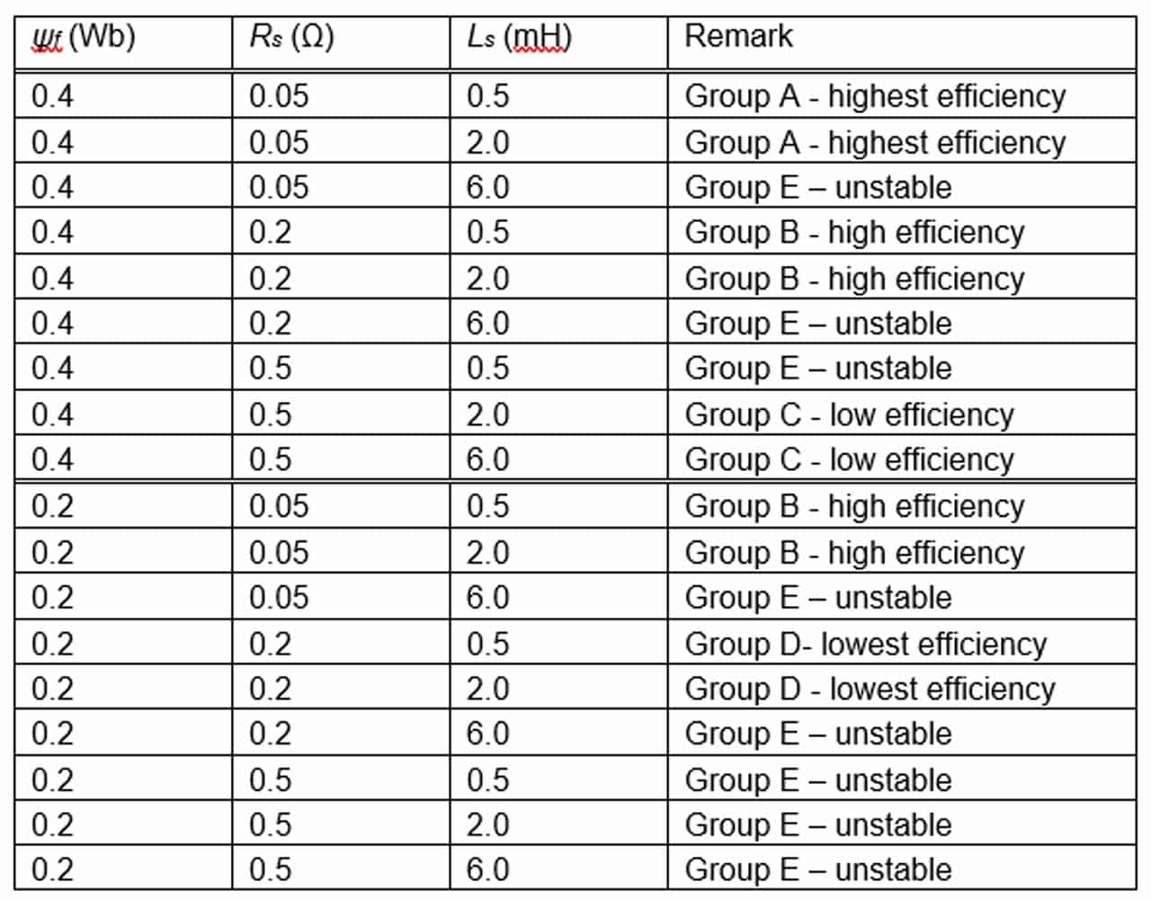
Table 2 shows that 18 cases were simulated, i.e., three different Rs, three different Ls and two different Ψf. The results in Table 2 and Figure 2 show the power or energy consumption versus speed. Results are categorized into five groups, namely, A, B, C, D and E. There are eight Group E cases that are unstable. So, the performance could not be depicted in Figure 2. Therefore, only 10 cases are depicted in Figure 2. When Ls and/or Rs are/is high, the operation becomes unstable. When Ψf is high while Rs and Ls are low, a very highly efficient performance could be achieved.
3.3 Regenerative Braking
Under normal operation, due to the absence of ropes and counterweights, a ropeless elevator has to be braked under a regenerative mode when it is traveling downward. Of course, if the MULTI is equipped with a mechanical brake, it can only be used when the car has fully stopped. Furthermore, under emergency when there is a genuine power failure, regenerative braking should be the first means though the MULTI may be equipped with a mechanical safety gear.
The braking force produced in the process of regenerative braking was analyzed and the expression of minimum braking distance for safe braking of the elevator was derived (Gao et al., 2019). In that paper, by using the finite element method, the relationship between the braking force and car falling speed during the regenerative braking process was further analyzed and the influence of external series resistance and motor air gap length on the braking force was studied.
According to Janovsky (1993), the primary coils attached to the side of the guide rails described in the patent US 5234079A could be short circuited during an event of power failure to perform dynamic braking. And it was claimed, if the percentage impedance of the primary coil is 5%, the descending speed can be kept to 5% of the rated value or lower.
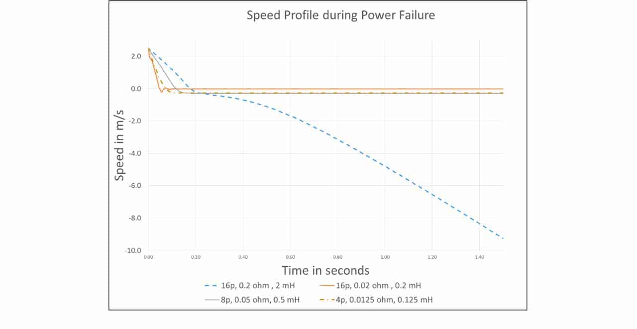
A formula to determine the terminal falling speed of the elevator under such a condition was derived, as shown in equation 4.
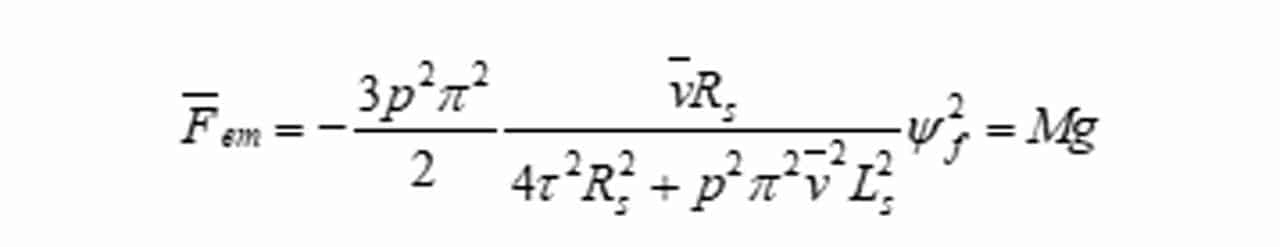
Here, M is the full mass of the car including everything, i.e., the cage, facilities and the full load. v— is the terminal speed. By solving the quadratic equation 4, it is possible to estimate such terminal speed based on machine parameters. And the simulation results under selected combinations are shown in Figure 3. It can be seen that a very low terminal speed — lower than the normal maintenance speed — could be obtained with less pole number, smaller Rs and Ls. Under such a low terminal falling speed, the burden on mechanical safety gear design could be very much reduced. It was proposed in So et al. (2018) that the method of pole changing could be used here.
3.4 The Existence of Saliency
It is very often unavoidable that saliency exists because it is a common design in motor construction. Equation 2 is revisited. When, Ld ≠ Lq, the driving force becomes more complicated as it depends on both sinδ and sin(2δ). Then, a more sophisticated control algorithm is required. This situation was further studied by the authors (So et al., 2019). When there is no saliency, two controllers are considered good enough (So et al., 2018), one for id and one for iq. Very often, id is adjusted to be as close to zero as possible for a higher torque-to-current ratio. With saliency, one more controller was added to provide the set-point of iq while the set-point of id was kept constant. As a matter of fact, the idea of maximum torque per armature current method suggested for rotary permanent synchronous motors (Morimoto et al., 1994) could also be adopted here for LPMSMs to determine the desirable relationship between id and iq whenever iq changes as a response to torque changes.
4. Conclusion
In this paper, the rationales of why ropeless elevators based on LPMSMs will become the future trend are highlighted, followed by a brief description of the world’s unique demonstration. Then, various technologies involved to realize such a system are discussed, including the overspeed governor design and the improvement of thrust of LPMSMs by others. Then, various previous studies by simulation carried out by the authors of this paper are briefly reviewed with emphasis on energy consumption, regenerative braking and pole saliency. It is hoped that more researchers could look into this elevator design of the future for the betterment of super-high-rise building services systems.
References
[1] Appunn R., Frantzheld J., Jetter M. and Loser F. (2018), “Multi-rope-less elevator demonstrator at test tower rottweil”, Transportation Systems and Technology, Vol. 4, No. 3, 80-89.
[2] Appunn R., Frantzheld J., Gerstenmeyer S., Jetter M. and Loser F. (2016), “Multi – new technology of a people transportation system for mid and high-rise buildings”, Proceedings of MAGLEV 2016, the 23rd International Conference, Berlin.
[3] Ascher K. (2013), The Heights: Anatomy of a City, Penguin Books, N.Y., 32-96.
[4] Boldea I. and Nasar S. (2001), Linear Motion Electromagnet Devices, Taylor & Francis, N.Y.
[5] Cui F., Xun Z., Xu W., Zhou W. and Liu Y. (2020), “Comparative analysis of bilateral permanent magnet linear synchronous motors with different structures”, CES Transactions on Electrical Machines and Systems, Vol. 4, No. 2, 142-150.
[6] Cao L., Chau K.T., Lee C.H.T., Liu W. and Ching T.W. (2021), “Analysis of air-gap field modulation in parallel-hybrid-excited harmonic-shift machines”, IEEE Trans. on Magnetics, Vol. 57, No. 2, 1-6.
[7] DOE (2016), How Maglev Works, energy.gov/articles/how-maglev-works.
[8] Gao Y., Xu X., Lu J., Sun Z., Chen S. and Liu Z. (2019), “Energy consumption braking characteristics analysis for multi-car elevator system”, Proceedings 2019 22nd International Conference on Electrical Machines and Systems, doi: 10.1109/ICEMS.2019.8921491.
[9] Glatzel K. and Schulz H. (1980), “Transportation: The promise of maglev, tests will continue with a high speed vehicle and track incorporating a linear motor”, IEEE Spectrum, Vol. 17, 63-66.
[10] Halliday D., Resnick R. and Walker J. (2013), Fundamentals of Physics, 10th Edition, Wiley, N.Y.
[11] Hu C., Cui H., Li X., Liu X. and Huang S. (2021), “Thrust characteristic improvement of permanent magnet linear synchronous motor based on multiobjective optimization”, Proceedings 2021 13th International Symposium on Linear Drives for Industry Applications, 1-5.
[12] IBM News Room (2010), “IBM survey shows strengths, gaps in u.s. office buildings”, 03.ibm.com/press/us/en/pressrelease/30191.wss.
[13] Janovsky L. (1993), Elevator Mechanical Design, 2nd Edition, Ellis Horwood, N.Y., 20.
[14] Morimoto S., Sanada M. and Takeda Y. (1994), “Wide-speed operation of interior permanent magnet synchronous motors with high-performance current regulator”, IEEE Trans Industry Applications, Vol. 30, No. 4, 920-926.
[15] Morizane T., Kimura N. and Taniguchi K. (2000), “Simultaneous control of propulsion and levitation of linear induction motor in a novel maglev system”, Proceedings of the 3rd International Power Electronics and Motion Control Conference, Vol. 1, Beijing, IEEE, CES and NSFC, August, 127–131.
[16] Onat A., Kazan E. and Takahashi N. et al (2010), “Design and implementation of a linear motor for multicar elevators”, IEEE/ASME Transactions on Mechatronics, Vol. 15, 685-693.
[17] Onat A. and Markon S. (2022), “Theoretical and experimental analysis of eddy current contactless speed sensors for linear motor elevators”, IEEE Sensors Journal, Vol. 22, No. 7, 6345-6352.
[18] Pang L., Zhao C. and Shen H. (2021), “Properties of adjusting magnetic field of hybrid excitation synchronous machine with tangential accumulation of magnet field shunt-wound magnetic path”, Proceedings 2021 24th International Conference on Electrical Machines and Systems, 1538-1543.
[19] So A. and Chan W.L. (2018), “A study of linear pmsm driven ropeless elevators”, Building Services Engineering Research & Technology, Vol. 40, No. 1, doi.org/10.1177/0143624418797604.
[20] So A. and Chan W.L. (2019), “Further study of linear pmsm driven ropeless lifts with consideration of imperfections by simulation”, Building Services Engineering Research & Technology, doi: 10.1177/0143624419840767.
[21] Souissi A., Abdennadher I. and Masmoudi A. (2021), “On the enhancement of the thrust production of lpmsms: application to ropeless elevators”, Proceedings 2021 16th International Conference on Ecological Vehicles and Renewable Energies, doi: 10.1109 / EVER52347. 2021. 9456599.
[22] Takahashi N., Yamada T. and Miyagi D. et al (2008), “Basic study of optimal design of linear motor for ropeless elevator”, Proceedings of the 7th International Conference on Computation in Electromagnetics, Brighton, IET, October, 202–203.
[23] Xu X., Zhang Y., Feng H., Zhao Y. and Zhou M. (2022), “Multi-objective optimisation design of a suspension-guided permanent magnet synchronous linear motor for ropeless elevator”, IET Electrical Power Applications, Wiley, doi: 10.1049/elp2.12247.
[24] Yang D., Kim K., Kwak M.K. and Lee. S. (2017), “Dynamic modeling and experiments on the coupled vibrations of building and elevator ropes”, J. Sound & Vibration, Vol. 390, pp. 164-191.
[25] Yeang K. (1996), The Skyscraper bioclimatically considered: A Design Primer, Academy Editions, London.

Get more of Elevator World. Sign up for our free e-newsletter.
![]()


![]()