System Analysis and Architecture Methodologies to Drive Innovative Electrical Systems
May 1, 2015

by Daryl J. Marvin, Dang V. Nguyen, Peter Herkel and Dirk H. Tegtmeier
This paper was presented at  Paris 2014, the International Congress on Vertical Transportation Technologies, and first published in IAEE book Elevator Technology 20, edited by A. Lustig. It is a reprint with permission from the International Association of Elevator Engineers
  (website: www.elevcon.com). This paper is an exact reprint and has not been edited by ELEVATOR WORLD.
ABSTRACT
When requirements, constraints, or customer expectations change, it can have a substantial impact on the desired elevator electrical system configuration. These changes could be a result of global or regional trends (e.g. environmental sensitivity), new fundamental system requirements (e.g. super high rise buildings), code (e.g. Programmable Electronic Safety), or technology advancement. By proper use of system analysis and architecture methodologies, innovative electrical system designs can be achieved that meet and exceed customer expectations.
The results of this process will be illustrated through several case studies.
- Super high rise electrical system
- Optimized machine-roomless architecture
- Battery operated elevator
1. INTRODUCTION
The electrical system architecture of an elevator product, once established, typically does not change in a rapid manner. As requirements and customer needs evolve over time, the traditional approach is to introduce these changes in an incremental manner to meet new market demands.
While this “bottoms-up” approach is low risk and minimizes interface changes, the resulting electrical system architectures and products tend to be suboptimal.
The alternative method is to architect the electrical system using a “top-down” approach. While this approach results in products with significantly increased values to the customer, it requires a more structured and analytical process for architecting the system.
Subsequent sections of this paper will give a synopsis of methods and tools useful to the electrical system architecting process. In addition, three resulting elevator electrical systems will be examined in detail as case studies.
2. METHODS AND TOOLS
There are many structured methodologies and tools that exist to assist in the creation of a desired architecture. Fundamentally, these methodologies espouse a systematic approach over an empirical approach of design. Some of the key steps of these methodologies are:
- Understanding of needs from important stakeholders
– Riding public
– Building owners
– General contractors
– Code authorities
- Identify Functional Requirements from customer needs
- Functional Decomposition for identifying more detailed functional needs of the system
- Functional Synthesis to group functions together based on a given criteria
- Functional to Physical Mapping to allocate functions to physical entities
A central idea in the above approach is to think functionally when designing products (Suh 2001). This will help to transform the customer needs into a set of specifications, or functional requirements. The Functional Requirements are “what we want to achieve”, and the act of design is to map these to design parameters in the physical domain (“how will we achieve it”).
Another salient feature of design methodologies is that they are principle-based. That is, general principles or axioms exist that can be applied to design good architectures. An example of this is the Independence Axiom and Information Axiom (Suh 2001). The Independence Axiom states that the design solution must maintain the independence of the functional requirements. A design parameter in the physical domain satisfying one functional requirement cannot affect another functional requirement.
The Information Axiom states that information content of the design should be minimized. Another way to look at this axiom, as applied to the functional synthesis step above, is to group functions together in such a way that the interface with other function groupings is minimized. For multiple designs that satisfy the Independence Axiom, the one that also satisfies the Information Axiom is considered the best design.
The process of functional to physical mapping should also take into consideration additional physical requirements of the system, such as available space, component access requirements, etc. As this process is being accomplished, there are often additional functions that are found to be required in order to meet the system objective.
For example, it is common in an elevator electrical system to have functionally related items (such as elevator demand fixtures and the dispatcher) required to be in physically different locations. There are then additional functional requirements for additional communication and power connections.
The methods described above are augmented by the use of various computer-based tools in analysis and modeling. As illustrated in the case of Super High Rise Electrical System, modeling is necessary to evaluate system performance because of the radical change in communication architecture of the electrical system. Additionally, building physical prototype of the full scale system is not feasible due to the large number of nodes
3. CASE STUDIES
3.1 Super High Rise Electrical System
3.1.1 Challenge
In high rise elevator systems, the magnitude of the complexity of the electrical system is very high. The combination of the increased group size, increased rise/number of floors, and speed pose significant challenges, especially as the height of the world’s tallest buildings continues to increase. Some of these challenges are:
- Weight and associated system impact of the traveling cable
- Number of nodes and total length of communication to hall fixtures and safety devices (e.g. door locks)
- Complexity of maintenance and service with size and scope of entire system
3.1.2 Technical Approach
In traditional elevator electrical systems, discrete interfaces are still the predominant method of signaling, especially if the information is safety-related. Recent advances in elevator code (Programmable Electronic Safety) and technology (low cost bus communication interface) have allowed for the implementation of a CAN bus-based architecture to eliminate discrete wires used for safety-related signals. While this approach has advantages in solving some of the challenges listed above, the bus-based architecture has potential impact on signal delay and system performance due to shared processing and communication resources.
Figure 1 shows a subset of the bus structure used to transmit both safety and non-safety related messages within the electrical system. The Safety Interface Board at the elevator car collects and processes all the discrete safety-related signals on the car and transmits them to the Safety Subsystem in the Controller. The Safety Subsystem in the Controller qualifies all the safety related signals before sending them to all the other modules.
All the other non-safety modules, such as the load weighing and controller also communicate over the same CAN bus. In order to successfully deploy such an electrical system solution, it is critical to be able to assess the effect of transmitting both safety and non-safety related messages on the same physical bus.
3.1.3 Critical Analysis
A framework for analyzing and exploring communication system architecture was developed to assess critical parameter performance of the High Rise Electrical System (Ferrari 2012). The framework consists of an event based simulation environment developed using SystemC, libraries of hardware and software communication components, tools to import application model from MatLab®, and a means to define and configure system topology.
The model topology of the Car CAN bus and Drive CAN bus is illustrated in Figure 2. Each module contains a collection of functional elements representing the application behavior (FUNC_NODE), CAN Stack (CAN_Stack), CAN Driver (CAN_Driver), and CAN controller hardware (CAN_Controller). In addition to the individual modules, each CAN bus is also modelled as a functional element and the connections to the CAN bus from each module is defined by the user. Other parameters defined prior to the execution of the model includes CAN bus speed, input stimuli (car calls), message arrival rate, and message dead line.
The modeling framework allows for a flexible way to explore different system architecture configurations and network topologies. Simulation of actual elevator bus messages allows for a quantitative evaluation of architecture decisions. Furthermore, the limit of the system can be assessed by modeling increasing car speed and building rise (longer bus length). Message arrival rates are increased with increasing car speed resulting in higher bus utilization.
During initial development, the simulation showed potential issues with queue overflow and dropped messages; these issues were then confirmed with lab data. Subsequent modifications to the configuration of the messaging framework that solved these issues were then made and evaluated by using this same modeling framework and verified through lab data.
3.1.4 Customer Benefits
By having safety functions implemented in software and using a network topology for communication of both safety and non-safety related information, many benefits were realized. The significant reduction in discrete wiring allowed for lower traveling cable weight, which has many beneficial system impacts including reduced propulsion power and the resulting higher system energy efficiency. The higher reliability components used in a solid state safety chain improves system availability. Additional functionality was also implemented that made bypassing of devices well controlled. In this system, these “smart jumpers” are implemented via software built to be transient in nature, and therefore not possible to be accidently left in place. A modeling framework provided the ability to model and simulate critical performance parameters, which allowed such an electrical system architecture to be effectively designed and delivered with high confidence and reliability.
3.2 Optimized Machine Room-less Architecture
3.2.1 Challenge
Machine room-less elevators are the major market in Europe for the low and mid- range application. The control architecture in many elevators is still based on the architecture that had been originally designed for elevators with machine room. Although modifications were made to accommodate the additional requirements of machine room-less elevators, the control architecture was not able to keep up with the changes in the requirements customers are demanding today:
- No aesthetic impact of the entrances
- Increased use of hoistway space
- Sensitivity for power consumption
- Capability in black-out situation
3.2.2 Present Situation
The control elements that formerly resided in the control cabinet inside the machine room have been distributed within the hoistway and one of the entrances for their application in a machine room-less elevator.
This has led to several points that were identified as major obstacles to match the control architecture with the changed customer requirements.
- The signal transmission is done with a mix of different channels and topologies
- The former central power supply is split into various transformation points.
A back-up power supply for emergency and rescue operation in case of black-out situation has added complexity to the power architecture
3.2.3 Technical Solution
In order to define an optimized control architecture, the tools and methods described earlier were applied. The result is a re-allocation of functionalities between the main components of the electrical system. The optimization strategy was focused on two elements:
- Simplification of signal architecture
- Simplification of power architecture
- Optimization of physical location of functionality
A simple signal architecture was achieved by Serialization
- Replacing discrete signal wires with a serial bus system
- Defining a serial bus topology
- Applying the serial bus to all main components of the control system
- Additional benefits by improved information interchange between the components
A simple power architecture was achieved by:
- Establishing a central system power supply
- Defining a serial bus topology
- Inclusion of the back-up battery as part of the central system power
- Additional benefits by higher efficiency and size reduction
Optimizing the physical location of functionality resulted in relocating some functionality from the controller to the car. This resulted in:
- Reduction in signaling requirements in the traveling cable
- Reduction in space required in the controller
3.2.4 Customer Benefits
The resulting benefits are
- Minimal aesthetic impact: The service and maintenance devices are assembled in the small door column; a specific control cabinet is not required.
- Improved use of the hoistway space: The package of the hoistway equipment is reduced in both volume and depth.
- Reduction of standby power consumption: The focus is to achieve VDI 4707 class A (VDI Standard, 2009).
- Integration of automatic and manual rescue: Only minor add-on components are required to provide full automatic rescue operation.
3.3 Battery Operated Elevator
3.3.1 Challenge
Over the last years, there was an increased focus on the impact of power supply stability on elevator operation.
Figure 5 gives an overview of the System Average Interruption Frequency (SAIFI) for selected European countries (CEER, 2014). As can be seen, SAIFI is in the range of 0.3 to 4 (outages per year).
Even if these values seem low, there were and are products available that provide emergency rescue operation for an elevator. These products traditionally use separate systems that are both space consuming and costly. Driven by the customer focus on this topic, automatic rescue functions were integrated into the newest product releases without requiring significant more space for control components. Main enablers for this integrated approach are:
- Gearless drives with Permanent Magnet Synchronous Motors
- Extended control capabilities by regenerative drives
- Standardization of voltages inside the control/drive system
- Using the gravity driven car direction for rescue operation
- Limited number of rescue runs/year
In other regions, especially in emerging countries, the situation of power supply stability is quite different.
Figure 6 shows data gathered from Otis Field engineers for different regions in India. Even though the study is experiential, it clearly shows some significant differences from the European data.
- Power outages in this graph are per day instead of per year
- Most areas have single digit power outages per day
3.3.2 Technical Solution
In order to provide a solution to the increased needs for power quality concern, a different approach was utilized. Instead of continuing to incrementally improve the battery supported elevator (i.e. Automatic Rescue Operation), the desired architecture is a fully battery driven elevator (i.e. seamless operation).
While this architecture has several challenges such as the compromise between battery voltage level and motor voltage required for driving the elevator, there are many customer benefits that result.
- Autonomous, seamless operation in power outage
- Single phase supply
- Peak shaving (only average power from grid)
- Compatible to alternative energy sources
These features make this battery driven elevator an appropriate candidate to fulfill customer expectations in areas with very unstable power grid conditions. Single phase supply and peak shaving also provide cost advantage in some areas compared to standard 3-phase elevators.
In addition, extending the battery driven elevator to use alternative energy sources such as solar cells or windmills is very simple, since energy storage and management capability are already included in the product.
4. CONCLUSIONS
By proper use of system analysis and architecture methodologies, innovative electrical system designs can be achieved that meet and exceed customer expectations. Based upon the challenges being addressed, there are often fundamentally different solutions required.
This has been shown in several case studies, ranging from super high rise elevators, low rise machine room-less elevators, and battery powered elevators. By continuing to use these analysis and architecture methodologies, future requirements, constraints, and customer needs will continue to be successfully addressed.

Figure 2. Model Topology 
Figure 3. Present Power and Signal Architecture 
Figure 4. Optimized Power and Signal Architecture 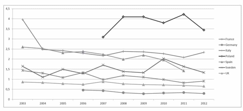
Figure 5. Unplanned Interruptions (SAIFI) for selected European countries 
Figure 6. Power Outages per Day in India
REFERENCES
Suh, Nam Pyo (2001), Axiomatic Design: Advances and Applications. Oxford University Press, New York.
Ferrari A., Ginsberg, D., Scholte, E., and Nguyen, D. (2012), “Scalable Virtual Prototyping of Distributed Embedded Control in a Modern Elevator System,” 7th IEEE International Symposium on Industrial embedded Systems.
VDI-Standard: VDI 4707: Lifts – Energy Efficiency, March 2009.
CEER (Council of European Energy Regulators), Benchmarking Report 5.1 on the Continuity of Electricity Supply, Ref: C13-EQS-57-03, Feb 2014.
Get more of Elevator World. Sign up for our free e-newsletter.


