
Telescopic Jacks
Sponsored
by Abe Salehpour and Don Brown
Telescopic jacks have been around for decades. A recent teardown of a nine-story 1920s building in downtown Los Angeles uncovered an elevator operated by a water hydraulic unit and lifted by a telescopic jack. While such early designs were functional, in many cases, they were more trouble than they were worth. Non-synchronized telescopic jacks, for instance, had poor ride quality, since each stage acted independently of the other in either direction. Today’s technology is far more advanced, and modern uses for telescopic jacks are far more versatile in that they satisfy the needs of a changing industry.
Learning Objectives
After reading this article, you should have learned:
♦ Why a telescopic jack would be installed
♦ About basic telescopic-jack designs, including two- and threestage jacks
♦ How the telescopic jack works
♦ The design requirements for using telescopic jacks
♦ About telescopic-jack applications
♦ About telescopic-jack installation and service, including resynchronization and jack packing replacement
Telescopic jacks provide solutions for complicated space requirements, modernization, new construction designs and cylinder replacements, while also possessing intrinsic benefits like contamination reduction. Other advantages include no hole having to be drilled, and no ropes, governors or safeties. In some applications that may require partial embedment into the pit floor, a two-to-four-stop hole-less telescopic jack would be recommended.
Telescopic Jack Operational Design
There are three approaches to telescopic-jack design: non synchronized, which allows each piston to fully extend before the next piston moves; external synchronization, which operates through a series of cables and pulleys or chains and sprockets that allow all pistons to move at the same speed and time (Figure 1); and internal synchronization, which operates with all pistons raising and lowering at the same speed and at the same time through the transferring of oil from an outer chamber to the inner chamber of the upper piston(s) (Figure 2). The latter design provides the best ride quality.
Within these three designs are two popular telescopic jack options that focus on internal synchronization:
- Two-stage telescopic jacks, consisting of an upper piston, a lower piston, a cylinder, a head bearing and a packing (on each piston). The lower piston is fitted with an internal packing, which is located at the lower end and rides against the internally honed cylinder (Figure 2).
- Three-stage telescopic jacks, consisting of an upper piston, an intermediate piston, a lower piston, a cylinder, a follower guide (required by code), a head bearing and a packing (on each piston). The intermediate and lower pistons are each fitted with an internal packing, which is located at the lower end and rides against the internally honed cylinders (Figure 3).
Each of these two telescopic jacks is designed for “guided” applications only. According to ASME A17.1/CSA B44, 3.18.2.7.2:
“The telescopic piston shall have each piston stage internally guided. If more than two stages are used, external guides shall be provided for each piston section. External guides shall be designed and constructed to comply with all applicable requirements of code section 2.15.”
In other words, the car frame to which the jack unit is attached is rigidly supported and guided. A guided stabilizer (follower) may be required on the moving head(s) to meet code requirements (Figure 3). Telescopic jacks are one-piece construction only.
How a Telescopic Jack Works
Up Direction
To best illustrate how the telescopic jack works, we have chosen the two-stage telescopic jack, which is internally synchronized (pistons rise at the same speed and at the same time). To follow the flow of oil and pressure, once an up call is registered, up sequencing begins by the controller, pump/motor and control valve. Beginning with the lower section (Figure 4), the lower chamber (#1) is attached to the inlet (#2), where oil is pumped. The chamber fills with oil, and the pressure below the internal seals (which separates the upper and lower sections) forces the lower piston (#3) to move upward.
Pascal’s Law explains what happens next: in a closed system, pressure is equal in all directions. Thus, the instant there is oil flow, the top piston begins to rise from the pressure provided by the movement of the bottom piston, which is being supplied oil from the inlet (Figure 5). This is accomplished by the transfer of oil from the green-colored area (top outer chamber) into the blue-colored area (inner chamber of the second stage). The rate of speed the pistons move is directly proportional to the flow of oil at the inlet. Both pistons are now moving simultaneously at the same speed. When fully extended, both pistons have moved half the travel of the total rise (Figure 5). Assume the total rise is 12 ft.; then, the upper and lower pistons each move 6 ft.
Down Direction
When a down call is registered and the down sequence is initiated, we will begin with Figure 5 and work backward to Figure 4. As the elevator is lowered by gravity, pressure is released in the lower chamber (#1), below the internal seals, allowing the oil to return to the tank. The lower piston begins to move downward. The oil in the upper section above the internal seals, starts transferring from the inner chamber back to the outer chamber of the second stage and the upper piston begins to move downward.
Design Requirements in Selecting a Telescopic jack
Major considerations in deciding which telescopic jack design to select are:
- Overhead
- Total travel
- Pit depth
- Gross load
- Horizontal clearance
- Car speed
The first consideration in selecting a telescopic jack is the size of the jack itself. The proper sizing is dependent on gross load and total travel (Figure 6). Next is car speed, which will dictate bottom and top overtravel (Figure 7). It is recommended to allow 2 in. more top overtravel than bottom overtravel. This is to allow more time between resynchronization. (See “Resynchronization” subheading below.)
For the telescopic jack to fit vertically, the following must be calculated (Figure 8). The actual overhead dimension is the sum of the cab height sitting at the top landing, plus top overtravel (TOT), plus 3 ft., 7 in., which is the code requirement for top refuge space. Add the total rise and pit depth to this dimension to find the total hoistway height:
- Bottom overtravel (BOT) = runby + spring compression + bottom clearance
- Gross load = car weight + capacity + upper piston weight (A three-stage jack or more should include all intermediate piston weights.)
- TOT = recommended bottom over travel + 2 in.
To determine if the telescopic jack will fit horizontally (Figure 9), we need to know the distance between the platform edge and the wall.
Telescopic-Jack Applications
An in-ground telescopic jack (Figure 10) is often the best choice for repair and modernization. In-ground telescopic jacks are also commonly used to replace in-ground single-stage jacks, where drilling for full travel is unavailable because telescopic jacks have a smaller total collapsed height.
The jack should be located in the load center of the elevator, and sealed and protected with PVC or jack liner. If the required clearance between the platform and hoistway wall are too small for hole-less telescopic jacks, the selection of in-ground telescopic jacks would be the best choice.
When modernizing or changing an in-ground jack to a hole-less application with a travel of 12-35 ft., the first consideration is to make sure the jack selected will fit between the platform and hoistway wall (Figure 9). Once the telescopic jack is determined to fit, the physical changes must be allowed for by adding a platen plate to the car frame and/or adding a secondary car frame for lifting. When changing an existing single-stage jack with a telescopic jack, be aware the speed of the car and pressure will change. It is possible the power unit may need to be modified, as well.
New construction will give you the versatility of choosing a twin-post hole-less telescopic jack with the flexibility of accommodating a partial in-ground jack if there is insufficient overhead.
Use the following to determine hole-less jack selection:
- When the total rise is 12 ft., single-stage hole-less jacks can be used.
- If total rise is 22 ft., two-stage telescopic jacks can be applied.
- For total rise of 35 ft., three-stage telescopic jacks can be utilized.
By using this hypothetical application (car speed of 125 fpm; 23-ft., 6-in. total rise; 8-ft. cab height; 3-ft., 7-in. refuge space; and pit depth of 4 ft.), it can be determined if the jack will fit vertically. The actual overhead available for this example based on the previous formulas is (8 ft. + 11 in. + 3 ft., 7 in.) 12 ft., 6 in. For total travel, use the formula “total rise + TOT + BOT,” as recommended in Figure 7. In this case, 23 ft., 6 in. + 11 in. + 9 in. = 25 ft., 2 in. For collapsed jack height, since it is a two-stage telescopic jack, divide the total travel by two and add a constant value (C ) of 18 in. for a collapsed height of 14 ft., 1 in. The C constant will change depending on the model and the manufacturer.
Now we proceed with calculating the minimum required overhead by filling in the missing measurements of the hoistway as shown in Figure 11. Beginning with “A” (top of piston), which is the sum of the collapsed height of 14 ft., 1 in. + BOT of 11 in. – pit depth of 4 ft. = 11 ft. Now, add the value of “B,” 2 in., which will be for the isolation pad and platen thickness for the top of the stile dimension. Next, add 1 in. to determine the highest point, then add the TOT. and add 6 in., which is the minimum clearance from the highest point of the stile, resulting in (11 ft. + 2 in. + 1 in. + 6 in.) 11 ft., 9 in. of minimum overhead. Since the minimum overhead is less than the actual available overhead, then the selected jack will fit vertically in the hoistway. If this were not the case, partially embedding the jack in the pit floor may be a solution. Complete sizing charts are available when ordering hole-less telescopic jacks. These formulas apply to dual hole-less and cantilever applications.
It is not recommended to use telescopic jacks for residential use, primarily because automatic resynchronization is not available in residential elevator controllers. Besides, most homeowners do not have service contracts for their elevator systems.
Telescopic Jack Service
When servicing a telescopic jack, first make sure there is no air in the system. Upon initial installation and/or repacking, careful removal of all air in the system will alleviate a bouncy ride and, in some cases, the need for resynchronization. There are air-relief ports on each stage of the telescopic jack to bleed out the air. Also, make sure the telescopic jack (as with all jacks) is plumb. Another condition that would create an out-of-synchronization situation is leakage or seepage, caused by a damaged piston or worn seals.
Resynchronization
Should the need for resynchronization occur, either the manual or automatic methods may be employed using a special circuit in the controller. If the pistons are out of synchronization, the jack unit(s) must be completely collapsed to resynchronize. Before starting the resynchronization process, each jack head assembly must be free of air. To bleed air, start with the top head assembly and continue downward. The air relief ports are located in flanges of the jack head assembies.
Manual Resynchronization
To perform manual resynchronization, disconnect the power from the system and remove the springs and spacers from the buffer stands. With a pressure gauge mounted on the jack side of the control valve, lower the car by opening the manual lowering valve until the pistons bottom out and the gauge reads “0.” Then, immediately close the manual lowering valve. At this point, the pistons should be completely collapsed, and the distance of exposed pistons between the heads and flanges should be approximately equal. Apply power to the system, raise the car and reinstall the springs and spacers back onto the buffer stands. Run the car up and down several times to ensure there is no air in the jacks and the system is synchronized. Repeat the process if necessary.
Automatic Resynchronization
In automatic operation, the special circuit in the controller should allow the car to rest on the buffer springs. This can be programmed to occur at a specific time of day or after a set number of elevator runs. Since the pistons must fully collapse in order to resynchronize, the length of the bolt connecting the platen to the upper piston must be long enough, at least the distance equal to the buffer stroke and bottom clearance (Figure 12) for this to happen. Make sure the top of the bolt meets code overhead clearance requirements.
Installation Instructions for EECO Telescopic Jacks
The installation process for Elevator Equipment Corp. (EECO) hole-less telescopic jacks is as follows:
- Carefully remove the outer protective cardboard from the jack, but leave the inner protective cardboards in place (Figure 15).
- Locate and remove the air bleeders (Figure 13) from their plastic pouch. Remove the pipe plugs from the jack inlet and the stationary (lowest) flange and install the air bleeders (Figure 14).
- Locate, plumb and install the jack in the hoistway.
- Connect the oil feed line and remove the shipping bracket (Figure 15). The upper section of each jack is filled with high-lubricity oil for ease of installation and operation.
- Adjust the relief pressure of the control valve so the system is pressurized without lifting the car (approximately 25-50 psi.).
- Open the air bleeder, starting at the upper head.
- Run the pump until all air is bled from the jack.
- Close air bleeder to prevent unnecessary oil loss.
- Repeat steps 6-8 for each head.
- Repeat steps 6-9 for each jack.
- Reset the control valve relief pressure.
- Jog pump/motor to move the pistons a few inches. Remove the inner cardboards from the jack (Figure 15).
- Raise the jacks to approximately half the travel to ensure the pistons stay plumb.
- Run the elevator at inspection speed to ensure a smooth operation with no binding and interfering of components.
Telescopic-Jack Packing Replacement
One of the myths about repacking modern telescopic jacks, created by earlier designs, is how difficult and time consuming this process is. In reality, repacking of telescopic jacks is not much more difficult than repacking a single-stage jack, although in some cases, a repacking might necessitate removing more than one head assembly. The following are typical instructions for EECO jack packing replacement. For preparation, the steps are:
- Run car above bottom floor to gain access to the pit.
- Safely secure the car.
- Disconnect piston from platen plate and lower pistons all the way by opening the manual lowering valve. There should be no pressure in the system with the pistons fully collapsed.
- Close all safety valves. Open and tag the mainline disconnect. Turn pit switch to “OFF.”
- Using rags, clean any oil and dirt from the top of the jack.
Follow these steps to replace the packing in the upper head:
- Remove the upper head bolts and head.
- Remove the packing seal, wiper ring, bearing and O-ring.
- Replace the packing seal, wiper ring, bearing and O-ring.
- Replace the upper head, making sure not to damage the O-ring.
Follow these steps to replace the packing in the lower head:
- Remove the upper head bolts and head.
- Unscrew and remove upper flange.
- Remove the lower bolts and head.
- Replace the packing seal, wiper ring, bearing and O-ring.
- Replace the lower head, making sure not to damage the O-ring.
- Replace the O-ring on the upper flange. Replace the upper head and flange, making sure not to damage the O-rings.
Follow these steps to replace the internal packing:
- Close all safety valves. Place a container under the drain/bleeder at inlet, then remove the drain/bleeder.
- Remove the upper and lower heads and unscrew flanges.
- Remove trapped oil between the lower piston and cylinder. It is recommended to use the EECO EP-1 evacuation pump to facilitate the removal of residual trapped oil.
- Screw on the upper flange again and fasten a lifting strap to it.
- Slowly lift up the lower piston until it comes out of the cylinder.
- Remove the screws at the bottom of the lower piston.
- Remove bearing cover, seals and bearing.
- Replace the transfer valve seal, packing seals and bearing. Make sure the U-shape of the internal packing seals is pointing in the right direction (Figure 16).
- Use the provided “install ring” to install the lower piston in the cylinder (Figure 16). Remove the install ring, and proceed with the rest of the installation.
Return to service using these steps:
- After all packings have been replaced and the jack has been reassembled, jog the motor to pressurize the system. This removes air through the bleeders. If the pistons start moving, stop and wait until they drop. Repeat jogging the motor until air no longer comes out of the bleeders.
- Close the bleeders when a steady stream of oil comes out, then carefully jog the motor to raise the pistons to the platen. Note that without the weight of the car, the upper piston sometimes moves faster, and when it hits the stop ring, the trapped oil in the upper section cannot go anywhere, so the lower piston will also stop, although it has not reached the stop ring. To extend the pistons higher, bleed some oil to get both pistons moving again.
- After the piston(s) has been fastened to the platen, and the car has been freed, run the car all the way down to obtain synchronization. Note that there should be no air in the jack(s).
Conclusion
Understanding how telescopic jacks work is the first step to properly using them. If care is taken to install an elevator and it is maintained properly, it will produce many years of continuous service. The same is true for telescopic jacks.
Telescopic jacks are addressing many problems that the logistics of modernization present; for example, space limitations, contaminated soil and, in many cases, labor savings during installation. Buildings with antiquated hy-draulic-elevator equipment with in-ground jack problems may necessitate frequent repair, but the unique function and design of the telescopic jack is helping solve many such problems.
Learning-Reinforcement Questions
Use the below learning-reinforcement questions to study for the Continuing Education Assessment Exam available online at www.elevatorbooks.com or on p. 117 of this issue.
♦ What is the difference between synchronized and non-synchronized telescopic jacks?
♦ What is the one additional parameter required by code on a three-stage telescopic jack that is not required on a two-stage jack?
♦ Why does a two-stage telescopic-jack piston only move half the total travel distance?
♦ What are the three main requirements for determining if a telescopic jack design will fit vertically in an elevator shaft?
♦ What are the main advantages in using telescopic jacks in new-construction and replacement projects?

Figure 1: A jack designed with external synchroniza-tion 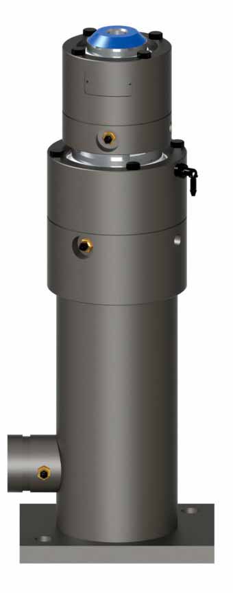
Figure 2: A jack designed with in-ternal synchronization 
Figure 3: A three-stage jack 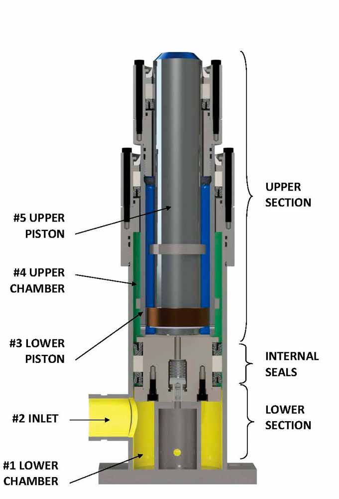
Figure 4: A two-stage jack, collapsed 
Figure 5: A two-stage jack, fully extended 
Figure 6: Typical EECO rating chart for sizing 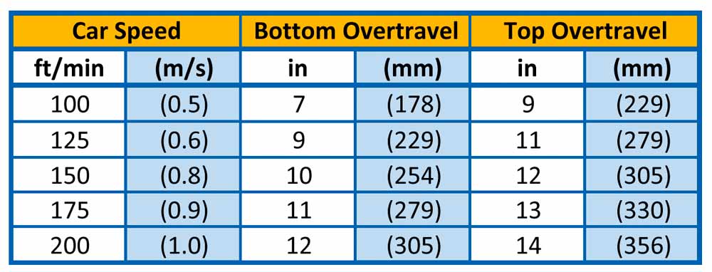
Figure 7: EECO overtravel recommendation chart 
Figure 8: Actual overhead 
Figure 9: Horizontal clearance 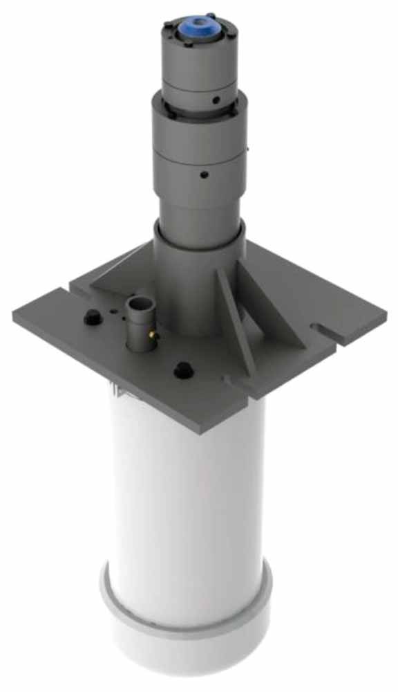
Figure 10: A typical in-ground telescopic jack 
Figure 11: Overhead illustration 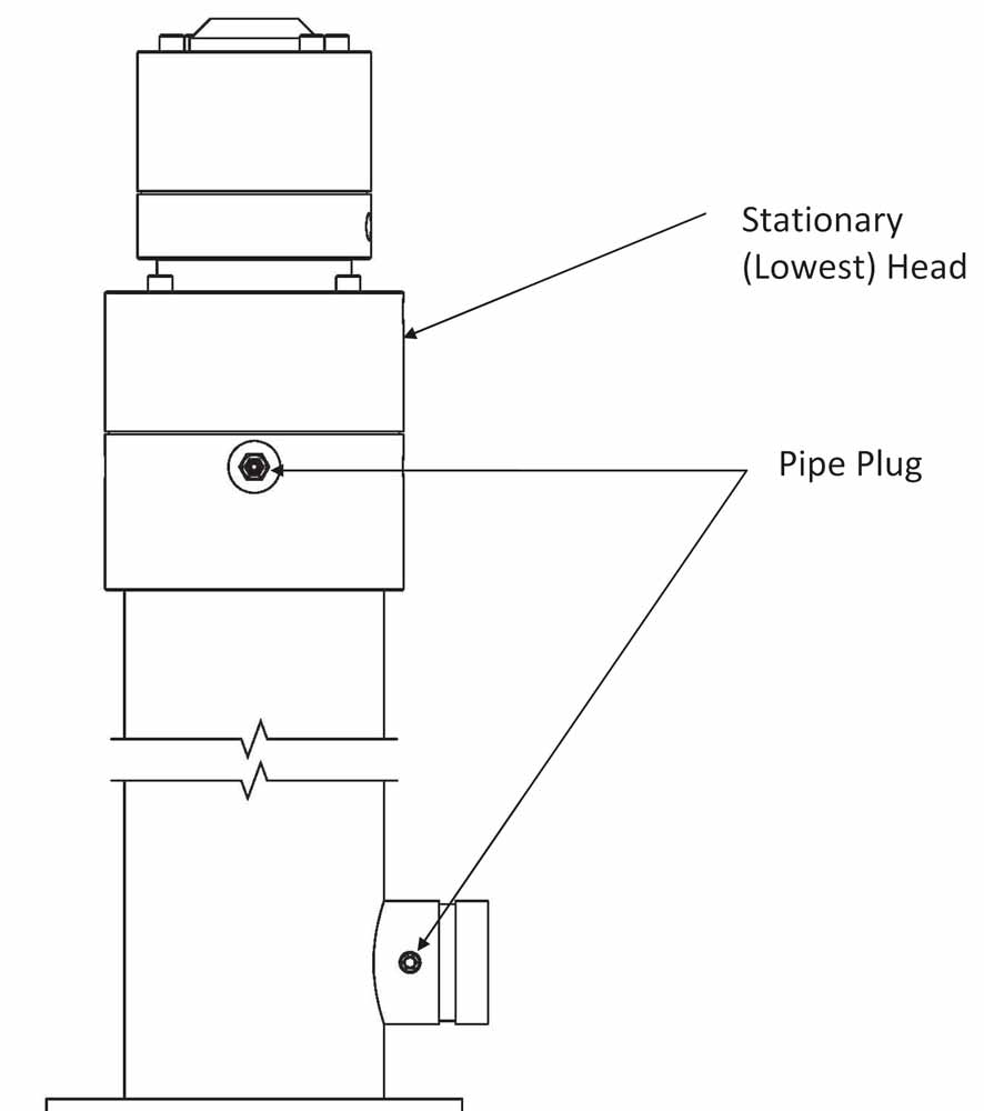
Figure 12: Connecting bolt length 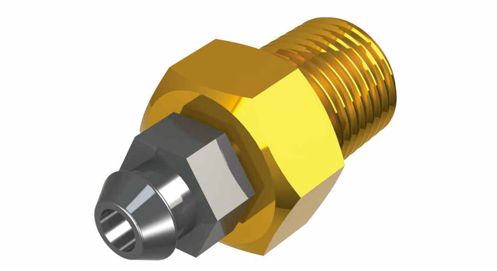
Figure 13: Air bleeder 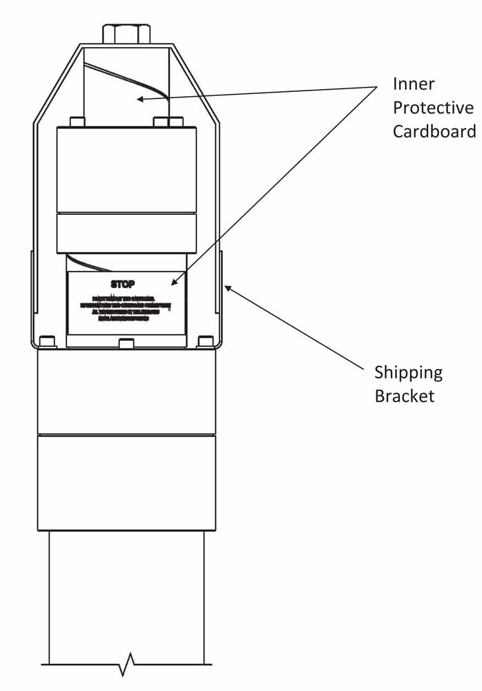
Figure 14: Air bleeder location 
Figure 15: Shipping bracket
Related Tags
Sponsored
![]()
Sponsored
Sponsored


![]()