The 1876 Centennial Exhibition, Part Two
Dec 1, 2013

Part one of this series examined the steam-powered elevators built by Otis Brothers in the 1870s as seen through the eyes of engineer Alois Riedler (1850-1936), author of the Austrian delegation report on elevators displayed at the 1876 Centennial Exhibition (ELEVATOR WORLD, November 2013). His report, titled “Passenger Elevators, Freight Elevators and Mine Hoists,” offered readers a concise summary of 19th-century American elevator technology. This summary included a survey of hydraulic elevator systems designed and built by firms such as Lane & Bodley (Cincinnati) and Crane Brothers Manufacturing Co. (Chicago), as well as systems designed by individual inventors associated with a variety of manufacturers. This article examines these systems as presented and illustrated by Riedler and as exhibited at the exhibition.
Riedler opened his discussion of hydraulic elevators with a detailed examination of Lane & Bodley’s horizontal hydraulic elevator engine. This system had been featured in an illustrated article that appeared in the American Artisan in July 1875 and had been the subject of several patents awarded in the early 1870s. Interestingly, there is no evidence that Lane & Bodley displayed this elevator in Philadelphia. While the exhibition’s official publications do reference the company and its products, which included a power mortising machine and a portable circular sawmill, there is no mention of an elevator display of any kind. The company manufactured a wide range of industrial equipment and machines, and it is possible the company included its elevators (belt-driven and hydraulic machines) in its overall display but were not highlighted such that they were brought to the attention of exhibition organizers or considered for recognition or awards.
Riedler’s interest in this system and its presence in his report may reflect the fact that this elevator was one of the first American systems published in Europe, and it is possible he may have read about it prior to attending the exhibition. The German publication Digest of Technical Literature for 1876 listed “Élévateurs Hydrauliques” in Moniteur Industrielle Belge (February 1876), “Hydraulische Hebevorrichtungen” in Dingler’s Polytechnisches Journal (June 1876) and an article in Allgemeine Deutsche Polytechnische Zeitung. Thus far, your author has had the opportunity to examine only one of these articles – “Hydraulische Hebevorrichtungen” (“Hydraulic Lifts”) – which consisted of a brief description of the elevator engine. (No illustrations accompanied the text.) The article’s unknown author claimed the elevator had “some interesting points,” and it (and possibly the other two articles) may have prompted Riedler’s interest in this machine. It is also possible that he may have seen the 1875 illustrated article that appeared in the American Artisan. The Repertorium der Technischen Journal-Literatur indexed this journal, which indicates it may have been available to a European audience. The presence of these articles also assured Riedler that at least some of his readers would have been familiar with Lane & Bodley’s elevator.
Riedler’s description highlighted the system’s essential technical and operational characteristics. He also provided an elevation and a combination plan/section drawing of the engine and three detailed drawings that depicted the operation of the control valve (Figures 1 and 2). These images were more “technical” and less evocative than the illustrations that accompanied the 1875 American Artisan article (Figures 3 and 4). However, a careful reading of these images clearly reveals the same elevator was depicted in each publication, with only minor differences in its representation (compare Figures 1 and 4).
Riedler stated this engine could be powered by water obtained directly from city water mains. Given the audience for his text, he expressed the normative operating pressures in “atmospheres,” assuming typical water pressures of 3-6 atmospheres (approximately 44-88 psi). As he had done is his description of Otis’ steam-powered elevators, he provided a table derived from a Lane & Bodley catalog that illustrated the system’s operational effectiveness at various loads and water pressures (Table 1). The costs were based on the Cincinnati Municipal Waterworks’ rate of 14.25 cents per 100 cu. ft. of water. Riedler reported that Lane & Bodley’s elevators “enjoyed extraordinary popularity” and were widely used throughout the U.S. Midwest.
The balance of Riedler’s report on hydraulic elevators was devoted to (often very brief) accounts of other hydraulic systems exhibited in Philadelphia. Jacob R. Ritter (1935-1912) of Reading, Pennsylvania, displayed “models of hydraulic lifts,” one of which was a “direct-acting hydraulic furnace lift,” while the other was a “hydraulic goods lift” that featured a “horizontal drive cylinder.” Both systems employed an accumulator used to increase the operating water pressure (a fact not mentioned by Riedler). No illustrations were included in Riedler’s report; however, Ritter’s patent drawings suggest the character of his furnace lift model (Figure 5). Philadelphia inventor William H. Harrison “exhibited the drawings of a direct acting hydraulic plunger elevator” designed for use in foundries. Interestingly, the official U.S. report on the exhibition claimed Harrison displayed “a small telescopic elevator,” which seems to contradict Riedler’s account. Unfortunately, no drawings of either system have been found.
Riedler also provided a brief description of two hydraulic elevators exhibited by Crane Brothers Manufacturing Co. One model was a prototype for the horizontal hydraulic elevator the company first marketed in 1877, which was similar to Lane & Bodley’s design. However, while the latter was a “pull-type” engine in which the plunger pulled the traveling sheaves away from a set of fixed sheaves mounted a set distance from the driving cylinder, Crane Brothers’ elevator was a “push-type” engine, which featured fixed sheaves at the rear of the cylinder (adjacent to the shaft), while the pistons pushed a set of traveling sheaves located in front of the cylinder. Riedler also reported the company had “recently” built several hydraulic furnace hoists, which featured a “horizontal or vertical drive cylinder in which steel bands are used for transmitting motion.” Unfortunately, nothing else is known about this intriguing design, and Riedler did not illustrate either of Crane Brothers’ hydraulic elevators (EW, September 2013).
Interestingly, Riedler did provide drawings of the telescopic vertical hydraulic elevator designed by Philadelphia inventor William Barnet Le Van (1829-1905). These drawings were derived from those prepared for Le Van’s 1875 patent: “Improvement in Hydraulic Elevators,” U.S. Patent No. 159,829 (Figure 6). Although Riedler stated Le Van had built “several” elevators in Philadelphia, only two have been identified, one of which was mentioned by Riedler: the direct plunger elevator built for French, Richards & Co. This elevator had been built in 1866 or 1867 and, according to Riedler, was designed for a maximum load of 5,000 kg and had a rise of 25 m. The cost of a similar (fully assembled) Le Van system in 1876 was US$8,000; the cost of a telescopic hydraulic elevator with the same specifications was US$7,000. In 1899, Le Van offered the following recollection of this installation:
“I would like to state that I built and erected a hydraulic lift at French, Richards & Co.’s, Tenth and Market streets, Philadelphia, about 25 years ago, the ram or plunger of which was 8 in. in diameter and 90 ft. in length. The machine was tested for one week, with an average load of 6,000 lb.; the speed of ram was 80 fpm, in rising, and when lowering, 160 ft. . . . It was in constant use for 17 years, during which time the actual cost for repairs was about US$150. The ram and platform were not balanced; it took 300 lb./sq. in. water pressure to balance them when the platform was empty.”
While Le Van had a successful engineering career, no evidence exists that suggests he played a significant role in the local elevator industry. There is, in fact, also no evidence Le Van ever built one of his telescopic elevators, and it is possible its inclusion and illustration by Riedler was simply due to its perceived novelty.
The final hydraulic elevator examined and discussed was the vertical system developed and marketed by William E. Hale (1836-1898) of Chicago. Although Riedler stated Hale exhibited drawings of his elevator, as was the case with Lane & Bodley, the official exhibition record made no mention of Hale’s elevator. He would have been seeking to capitalize on the recent publicity his design had garnered – it was featured in an illustrated article published in the November 20, 1875, issue of Scientific American; this article was republished in March 1876 on the front page of Manufacturer and Builder. The drawing that accompanied Riedler’s brief technical description followed the same pattern employed with Lane & Bodley’s machine: the details of the perspective drawing were simplified, and the elevator was illustrated by a combination elevation and section (Figure 7). The somewhat schematic nature of this drawing may reflect the fact that in 1876, Hale was marketing the concept of his new elevator, the actual production of which did not begin until 1878, when Otis Brothers purchased the patent rights and began building what it marketed as the “Standard Hydraulic Elevator.”
The conclusion of this series will examine the only foreign system included in Riedler’s report, the elevator designed by Mégy, Echeverria & Bazan of Paris, which was commended by exhibition judges for its “ingenuity, compactness and great utility.”
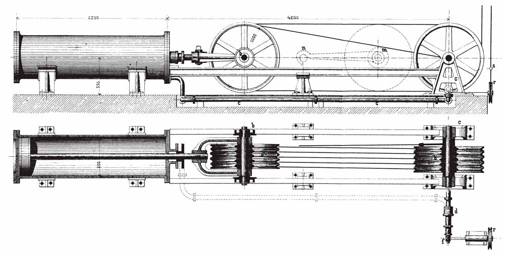
Figure 1: Lane & Bodley’s horizontal hydraulic elevator engine from Alois Riedler, Personen- und Lastenaufzüge und Fördermaschinen (1877) 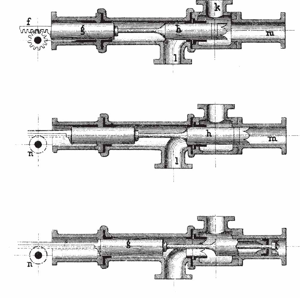
Figure 2: Lane & Bodley’s hydraulic elevator engine control valve from Alois Riedler, Personen- und Lastenaufzüge und Fördermaschinen (1877) 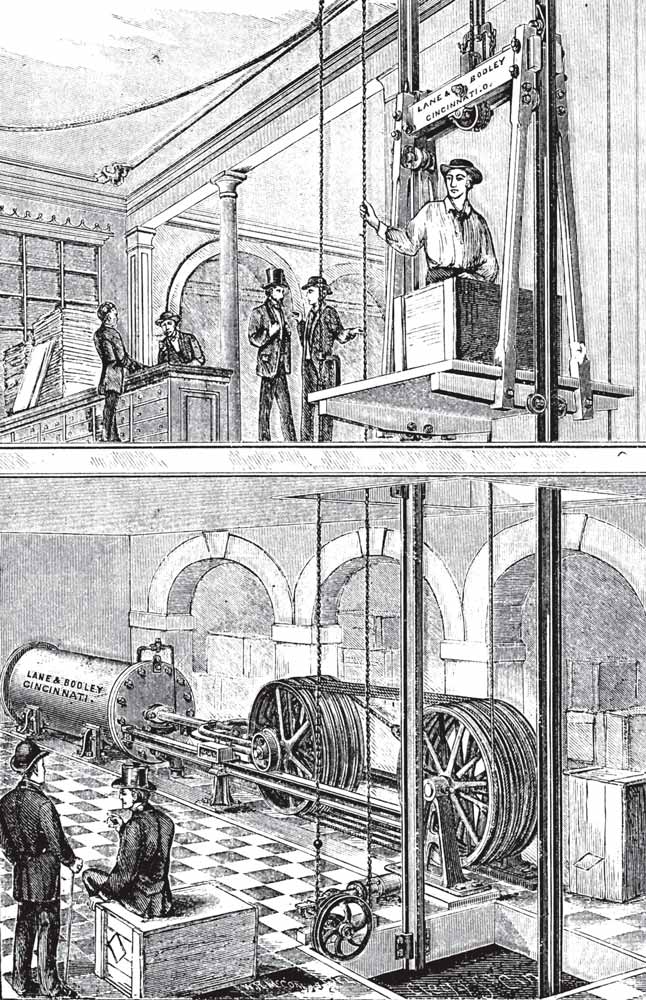
Figure 3: Lane & Bodley’s horizontal hydraulic elevator engine from “Hydraulic Elevator,” American Artisan, July 1875 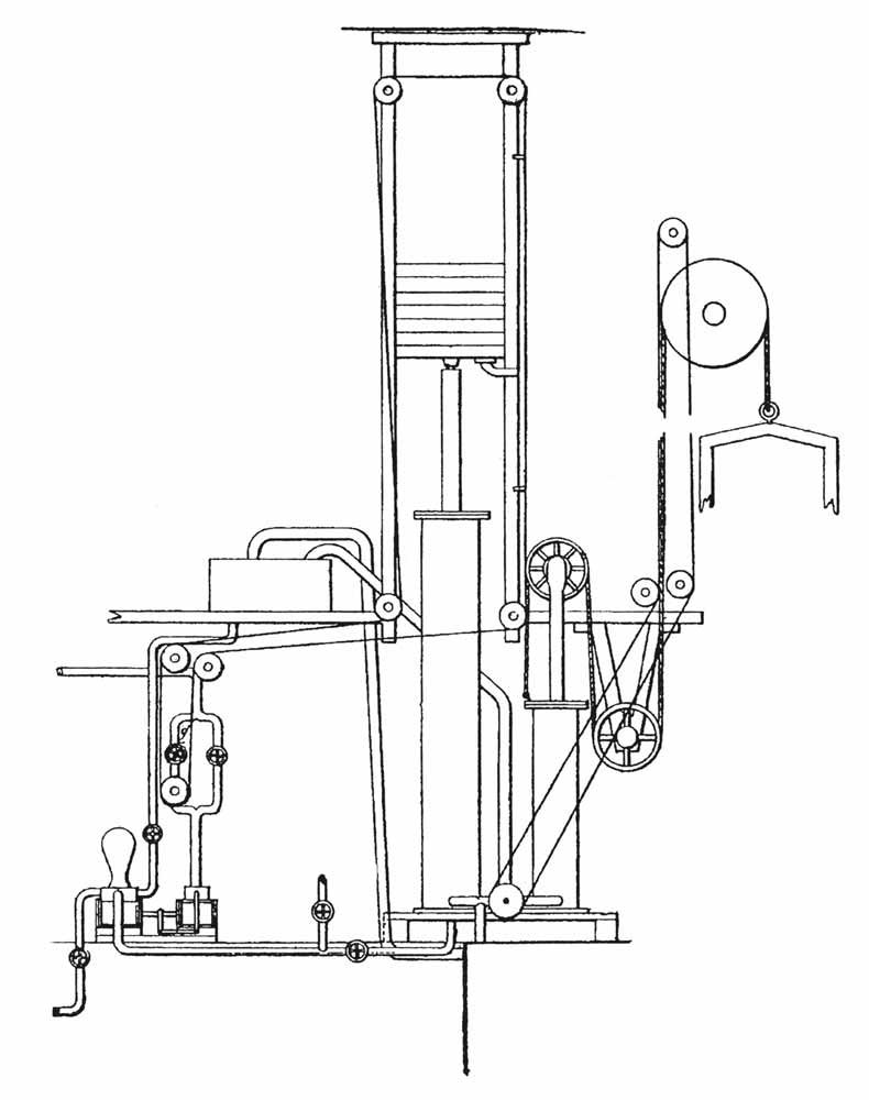
Figure 5: Jacob R. Ritter, “Improvement on Hydraulic Hoisting Apparatus,” U.S. Parent No. 133,2456 (November 19, 1872) 
Figure 6: (l-r) William Barnet Le Van, “Improvement in Hydraulic Elevators,” U.S. Patent No. 159,829 (February 16, 1875) and William Barnet Le Van’s telescopic hydraulic elevator from Alois Riedler, Personen- und Lastenaufzüge und Fördermaschinen (1877) 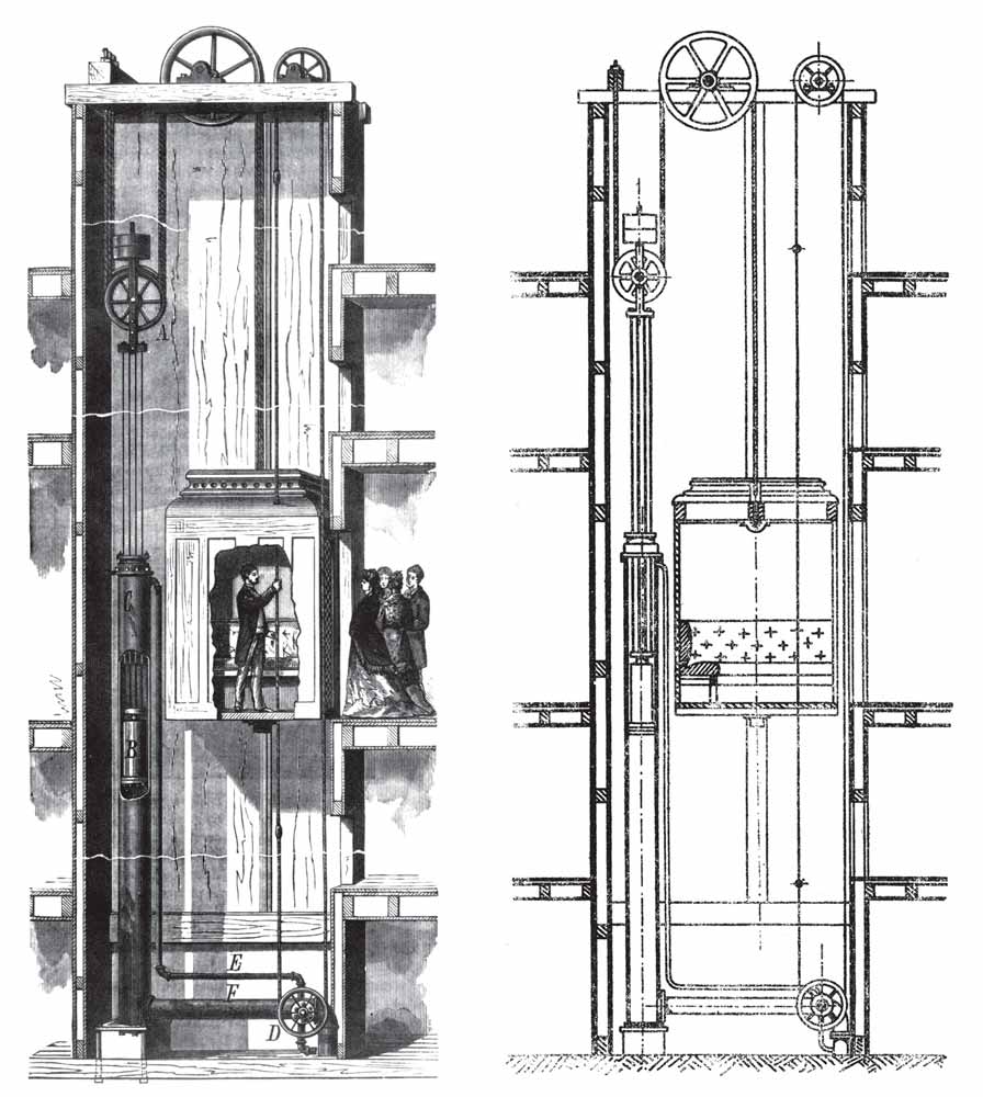
Figure 7: (l-r) “Hale’s Duplex Water Elevator,” Scientific American (November 20, 1875) and William E. Hale’s hydraulic elevator from Alois Riedler, Personen- und Lastenaufzüge und Fördermaschinen (1877) 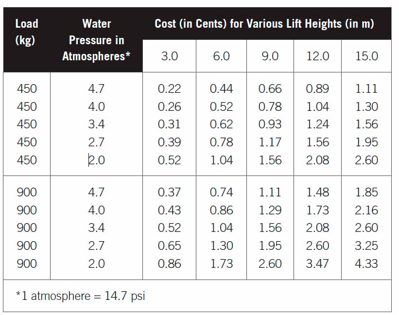
Table 1
Get more of Elevator World. Sign up for our free e-newsletter.


