The Gradatory Elevator, Part Two
Apr 1, 2014

An examination of the paternoster elevator’s inception concludes with investigations of Ellis’ patents and lone installation.
This article continues the investigation into the first paternoster-type elevator, which was designed in 1866 by Liverpool architect and civil engineer Peter Ellis and placed into Oriel Chambers in Liverpool in 1869. Part One addressed Ellis’ design of the speculative office building Oriel Chambers and the possibility that it was designed to accommodate a lift (ELEVATOR WORLD, March 2014). In fact, Ellis was one of the first to propose the use of lifts in office buildings. This technology had previously been limited to hotels and industrial or commercial buildings. However, his imagined use of his elevator was accompanied by a somewhat vague idea of how his elevator would operate and be placed within a building.
As depicted in Ellis’ patent drawings, the twin shafts, or “vertical trunks,” were located back to back, such that a person facing a shaft opening would only see an ascending or descending car, as its counterpart would be traveling in the rear shaft. Thus, a single elevator installation would have had shaft doors facing opposite directions, with each side serving a different travel direction. In his patent, Ellis depicted two side-by-side elevators (Figure 1). The labeling applied to the plan (a for up and b for down) implied that both elevators traveled in the same direction, thereby doubling the system’s capacity. Somewhat confusingly, this same labeling convention, when used on the sectional elevation, implied that the elevators worked in opposite directions, thus indicating potential riders would have ascending and descending options (Figure 2). However, the gearing arrangement represented throughout the patent was not designed to facilitate two elevators operating in opposing directions driven from a single shaft. (This inconsistency is also not addressed in the patent’s text.) Finally, the plan also depicts the paired elevator shafts as open on their opposite sides, which implied the paired elevators would be accessible from two approaches.
The car would be open on two sides: passengers would have had to very carefully stand in the middle of the small car to avoid contact with the cars moving in the adjacent shaft.
In addition to the operational inconsistencies found in the drawings (which are not addressed in the patent’s text), there is also the question of how Ellis’ elevator would be placed in a building. If, as its drawings imply, the elevator were intended to be accessible from two sides, its installation may have been such that it projected into a lobby space, whereby the prospective rider would have first seen the end wall of the shaft, then moved to the right or left, depending on the desired direction of travel (Figure 3). The individual shafts depicted in the patent are approximately 2 X 2 ft.; thus, the system would have a limited impact on space planning. However, if Ellis’ elevator functioned in this manner, riding in one of the cars, or “carriages,” would have been quite dangerous. Because the carriages could be accessed from two directions, the “rear” of the car in one shaft was also the “front” of the car on the other side. Thus, the car would be open on two sides: passengers would have had to very carefully stand in the middle of the small car to avoid contact with the cars moving in the adjacent shaft. It was, perhaps, this safety problem that led Ellis to propose using two side-by-side elevators moving in opposite directions, which, while technically possible (allowing the cars to have an enclosed “back”), was an expensive solution.
It is, perhaps, Ellis’ awareness of the above operational problem that explains the gap in the timeline from his design of Oriel Chambers to the installation of his elevator. The building was designed in 1863, construction was completed by mid 1865, and Ellis’ patent application was filed in July 1866, with the patent awarded in January 1867. Thus far, we have a steady path toward the invention of an elevator system that may have been intended to fulfill Ellis’ original desire to incorporate vertical transportation into his design. However, the elevator was not installed until October 1869.
How do we explain the two-and-a-half-year gap between invention and implementation? Although the following account is speculative, it is based on an intriguing (but, admittedly, limited) set of facts that supports its conjectures. That Ellis continued to have hopes for his lift design and may have continued its mechanical development is evidenced by his paying the considerable sum of GBP50 (US$83.38) for the stamp duty owed on his patent. This was reported in the July 16, 1869, issue of Engineering magazine, which, perhaps, suggests an awareness of his work or an effort by Ellis to attract publicity to his continued efforts. (It is unclear how editorial decisions were made at this time regarding the reporting of patent-related news items.)
The two published accounts of the October 1869 installation of Ellis’ elevator in Oriel Chambers both support the supposition that he continued to improve its design, and highlight the elevator’s unique design and method of operation. The first account, an article titled “A New Lift,” appeared in the November 12, 1869, edition of the Liverpool Daily Post. The author described the typical lift (and its limitations), followed by a description of Ellis’ elevator:
“There is now in operation at Oriel-chambers a very striking improvement upon the lifting machinery, which has, for some time past, been in use in our large warehouses. The old lift, it will be remembered, consists of a single box, raised or lowered by means of a rope, which can be managed by the person in the box. The disadvantage of this is that persons on the bottom floor wanting to ascend have to wait until the box has made its upward and downward journey, occupying, perhaps, a considerable time.
“Mr. Ellis has two spaces or box recesses, instead of one, for the working of the elevator — one an ascending passage, and the other a descending passage. He has several boxes, also, instead of one, which are worked continuously. . . as soon as a box ascends at the top, it passes over a pinion and adjusts itself in the descending space. When it reaches the bottom, it adjusts itself in a like manner into the ascending space, so that there is a continuous series of ascending and descending boxes. The great advantage of this elevator is that people can get on and off at any floor at any minute, for, while the machinery is at work, not a minute passes without an ascending or descending box appearing on each floor. Unlike the one box and one space machine, it requires no attendant to manage the ascent and descent — for the ascending and descending motion is continuous.”
The author noted, “The drawback, which suggests itself at first, is that timid people would not get in and out of moving carriages.” However, he reported, “Ladies and elderly persons, it has been found, experience no difficulty in entering or leaving the lift, the movement of which, it may be mentioned, is soundless, uniform and smooth.” The article concluded with the statement: “As the lift is perfectly open to anyone who may pass through Oriel-Chambers, people will be able, without trouble, to judge for themselves of Mr. Ellis’s improvements.”
The Daily Post article also assigned a unique name to Ellis’ new lift: it was referred to as “a gradatory elevator.” A version of this sobriquet also appeared in numerous advertisements in the Daily Post throughout November and December 1869:
“ORIEL-CHAMBERS, WATER-STREET. — Offices in this Fire Proof Structure to be Let. These premises are supplied with a Mechanical Gradatory or Person Lift, of continuous, safe, and easy use. 500 persons may ascend and descend in an hour. — P. Ellis, Patentee.”
The specificity of these terms and the use of the word “gradatory” raise the question of attribution: was this Ellis’ characterization of his invention or the newspaper’s? The Oxford English Dictionary notes that “gradatory,” defined as “proceeding by steps or grades,” was in use by the 1840s; however, its use was listed as “rare.” Although the word does not appear in Ellis’ patent, given that he defined his design as an “Improved Lift, Hoist, or Mechanical Elevator,” it may be reasonable to assume he should be credited with the terms “gradatory elevator” and “mechanical gradatory.”
Unfortunately, the Daily Post article provides only a limited technical description of the lift installed in Oriel Chambers. A more comprehensive description appeared in the December 4, 1869, issue of The Architect in an article with the somewhat awkward title “A New Description of Lift.” The unknown author of this article opens with a general introduction of the “new lift”:
“A Lift has been invented and patented by Mr. Peter Ellis, architect, of Liverpool, which we may class as a person lift, but which differs from any other in the fact of its having two shafts instead of one, with several cages or chairs in each shaft, and in moving continuously up one shaft and down the other (reminding us somewhat of the movement of the buckets to a dredging machine), the passengers entering or leaving without stoppage, although having the power to stop it in case of necessity.
“We consider this invention so important in relation to large sets of offices, hotels and the adoption of living in flats by the middle classes, that we give a description of the first completed specimen, which has been in use for some months in Oriel Chambers, a large block of offices erected by Mr. Ellis in the busiest part of Liverpool.”
This is followed with a detailed description of the lift’s components: the two shafts, “placed side by side” are each “about 2 ft. square” in size, and the carriages or chairs that traverse the shafts “consist of a light iron framework, about 7.5 ft. high, carrying at the top a step or bush.” Also, “The floor is of wood, made double, and contains friction-wheels some 12 in. in diameter, fitted with friction rollers round the edges.” A new feature, not referenced in Ellis’ patent, was an “important contrivance” that guided the cars around the top and bottom of the shafts:
“As the chairs are suspended freely, and, after passing the diaphragm at the top, their motion is changed from ascent to descent, it is evident that some important contrivance is indispensable, not only to do this, but to give the necessary regularity and precision of movement. This has been cleverly effected by a strong grip or clutch suspending over the shafts and descending considerably below the axle of the spur wheel. Bearing the belt into this clutch (which is brought into position by the motion of the ascending carriages) the slide of the chair frame enters, and the chair is rigidly and securely carried over, and delivered into the descent below the diaphragm, before leaving the clutch.”
The lift was powered by a “small two-horse engine,” the total lift height was approximately 40 ft., and “about half a minute” was required “for ascending from the lowest to the highest story.” The article also reported that “above 420 persons may ascend and descend within an hour.”
Thus, Ellis’ lift had a remarkably small footprint — approximately 2 X 4 ft. — and could have easily fit into one of the building’s stairwells. This placement would have required a 90° shift in the orientation of the lift’s operation. Given the use of the fiction rollers to guide the carriages’ vertical movement and the additional “contrivance” that ensured secure passage from ascending to descending shaft, it may be reasonable to assume Ellis modified his design. The 90° shift would have also solved the problems inherent in his original design, where the carriages were apparently open on two sides.
Figure 4 illustrates the revised design, which, if correct, would mean Ellis’ “gradatory elevator” was the first paternoster lift in both its conception (found in its 1866 patent) and implementation. Unfortunately for Ellis, in this instance, being “first” did not lead to either fame or fortune as a lift designer or manufacturer. He built only this single example of his gradatory elevator, and, although it remained in use well into 1880s (and possibly longer), it failed to attract attention beyond that of the local press and the lone article in The Architect. In 1873, Ellis chose to not pay the GBP100 (US$166.74) stamp duty required to extend the life of his patent, and this cleared the way for Frederick Hart, who, four years later, patented the design marketed as “Hart’s Cyclic Elevator” (EW, April and May 2012), which is often identified as the “first” paternoster lift. However, as this article series has shown, this prize should go to Ellis.
Your author would like to thank Mr. Graham Jones of the Liverpool Historical Society and coauthor of In the Footsteps of Peter Ellis: Architect of Oriel Chambers and 16 Cook Street, Liverpool for encouraging this investigation and for his assistance in obtaining source materials.
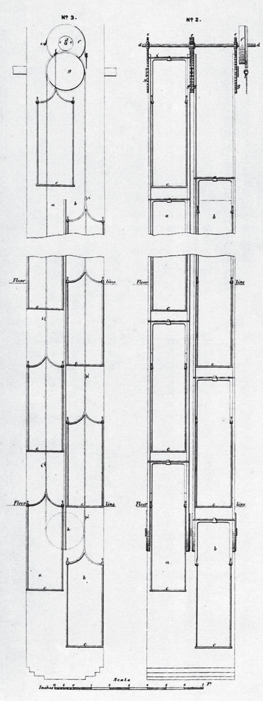
Figure 2: Front elevation, Ellis’ “Improved Lift, Hoist, or Mechanical Elevator”; again, a designates ascending, and b designates descending carriages. 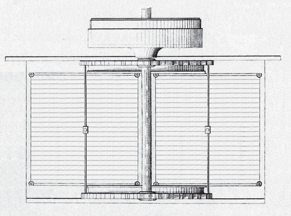
Figure 3: Plans: conjectural single and double installations of Ellis’ “Improved Lift, Hoist, or Mechanical Elevator” 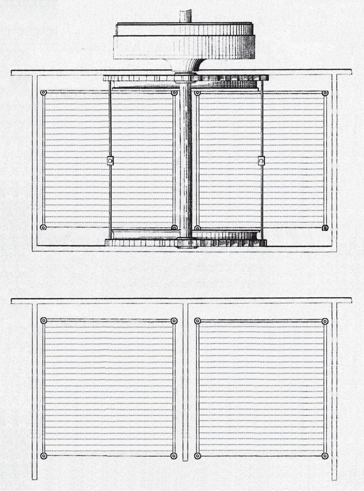
Figure 4: Plan: conjectural installation of Ellis’ “Gradatory Elevator” in Oriel Chambers, 1869

Get more of Elevator World. Sign up for our free e-newsletter.