The History of Operatorless Elevators: Traffic Control Systems (Part One)
Aug 1, 2023

The role of elevator operators decreases as systems become increasingly automated.
The first phase in the development of the operatorless elevator began in the last decade of the 19th century and extended into the first decade of the 20th century. This effort produced a machine that met the needs of private-residence owners — where it was first employed — and small apartment buildings. This latter use led to these machines being identified as using a “signal control” system of operation. While, prior to the invention of pushbutton control, waiting passengers did push a landing-button. This action sent a signal to the car operator, letting them know that they needed to stop at a given floor. Thus, the prospective passenger depended on the operator to bring the car to them. The phrase “signal control” indicated that passengers were no longer reliant on the operator, as the elevator’s operation was controlled by the pushbutton system. Although this system met the needs of buildings with light traffic demands, its potential to serve larger buildings with high-speed traction elevators led to the next phase in the development of operatorless elevators — a phase that, paradoxically, also relied on operators.
Once again, Otis was among the leaders in this effort; their design team was led by David L. Lindquist and included Edward L. Dunn and David C. Larson. Lindquist (1874-1944), born in Sweden and educated at the Technische Hochschule (Technical University) in Charlottenburg, Germany, immigrated to the U.S. in 1902. In 1904, he joined Otis, and by 1910, he had assumed the role of chief engineer. During his lengthy career, he played a significant role in the development of the modern elevator. Larson (1883-1971) also emigrated from Sweden (he arrived in the U.S. in 1900), and he also joined Otis in 1904. Prior to joining Otis in 1920, Dunn (1868-1946) had worked for the Burdett Rountree Manufacturing Co. (Chicago) and the Standard Plunger Elevator Co. (Worcester, Massachusetts). The team began their work in the early 1920s, an effort that produced six patents. The patents constituted three distinct sets and concerned three variations of an automatic elevator system. The first set was originally filed as a single application on February 3, 1925, and was later divided into three patents, two of which addressed the overall system design and one that addressed a switching mechanism (the patents were awarded in 1930 and 1933).[1]
The overall design was predicated on providing an automatic elevator system that, while utilizing an operator, limited their responsibilities to pressing floor buttons for passengers, closing and opening car and landing doors and starting the elevator. The car automatically stopped to pick up prospective passengers (in response to hall calls) and automatically stopped at floors selected by the operator. The system was also designed to signal a waiting passenger of a car approaching the landing in the desired direction of travel. The signal was only triggered by the hall-call button; however, if the car did not stop in response to a call button request, for example, it stopped to discharge a passenger, no arrival signal was provided. Lastly, the system was designed so that only one car in a bank of cars would stop at a landing in response to a call.
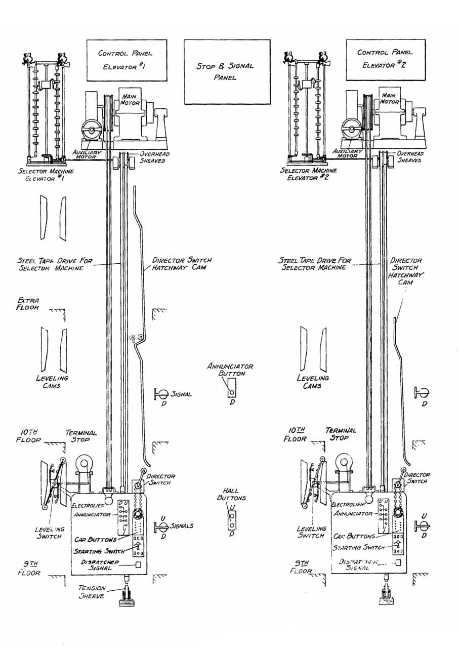
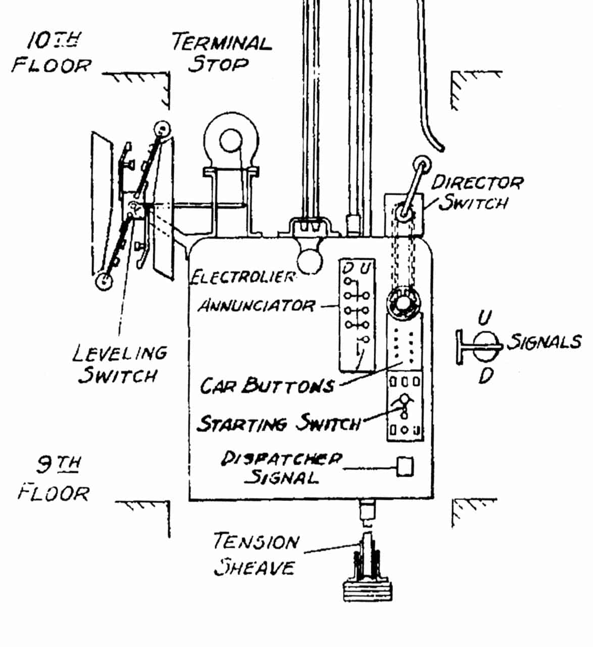
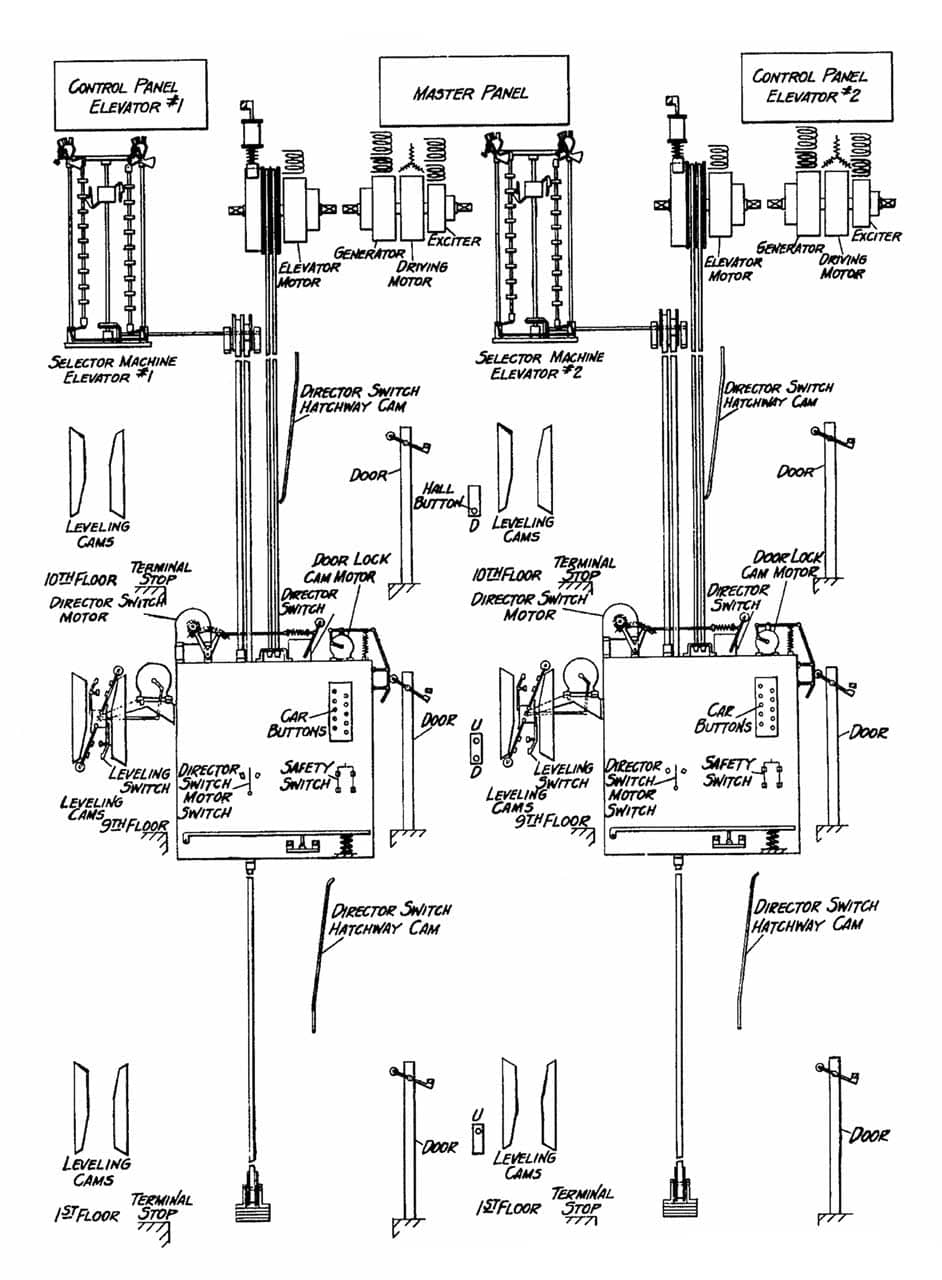
The system’s components were outlined in a schematic drawing that illustrated the design applied to a bank of two elevators (Figure 1). Critical components included individual elevator control panels, a master control panel (the stop and signal panel), floor selector machines and leveling switches. The latter reflected the recent development of automatic leveling systems, which were designed to improve the operation of high-speed elevators. A “director switch” communicated the car’s direction of movement to the master control panel. The shaft was equipped with “director switch cams” at the terminal floors that automatically reversed the direction of the car’s movement. This design also included a component that reflected its position mid-way between operator-controlled and automatic systems. The car featured an annunciator panel, which signaled to the operator which floor buttons had been pushed and the desired direction of travel (Figure 2). Given the system’s automatic operation, however, this would appear to have been a redundant feature.
An important new feature found in the car was the car operating box or elevator control panel. While the elevator was capable of automatic service, the multiplicity of functions included on the panel revealed the inventors’ reluctance to completely remove the operator from the car, particularly in large buildings equipped with high-speed traction machines. The car operating box included a safety switch, emergency switch, auxiliary motor switch, slow-speed switch, non-stop switch, starting switch, light switch and a handwheel (mounted at the top of the box) (Figure 3). The safety switch was used to stop the car in the event of an emergency; when activated, it cut off power to the main motor and automatically applied a dynamic brake to slow the car’s speed, after which a mechanical brake was applied to stop the car. The emergency switch, which was accessed by breaking a glass cover, allowed the elevator to operate with the car and landing doors open. It was intended for use in an emergency, such as a fire, where the doors might not function. The auxiliary motor switch shifted the operation of the car to the secondary motor that was used to level the car at the landing (as a car approached a landing the main motor automatically cut out and the auxiliary motor was engaged). This switch was utilized as an additional safety in the event the main motor failed.
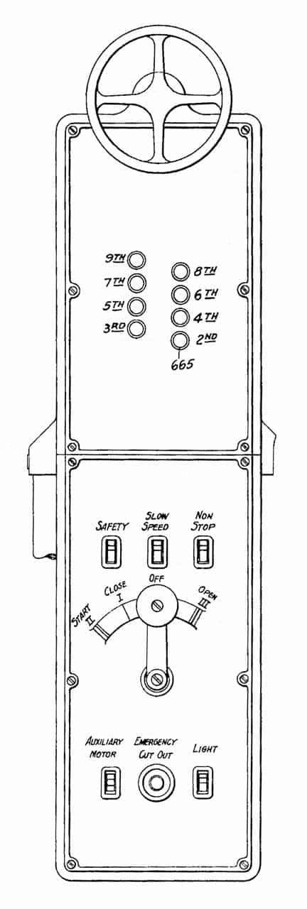
The slow-speed switch allowed the car to be operated at half-speed and could be used to moderate or adjust elevator traffic and the interval between cars. The non-stop switch allowed the operator to bypass floors and move quickly to a terminal floor (this was typically used when the car was full and could not accommodate additional passengers). The starting switch or lever had four positions: off or neutral (if the lever was released it automatically returned to the off position), start, close and open. When the car arrived at a landing, the operator would move the lever to the right and open the doors. After all passengers had boarded (and indicated their destinations), the operator would move the handle to the left, past the close position (thus shutting the car and landing doors) to the start position, and the car would continue on its journey. The light switch operated the car’s interior lights. The handwheel allowed the operator to reverse the car’s direction by moving the director switch atop the car. If the car was in the middle of a run traveling upward, and after a floor stop and the operator wanted to reverse direction, they would use the handwheel to communicate the change in direction to the control panel.
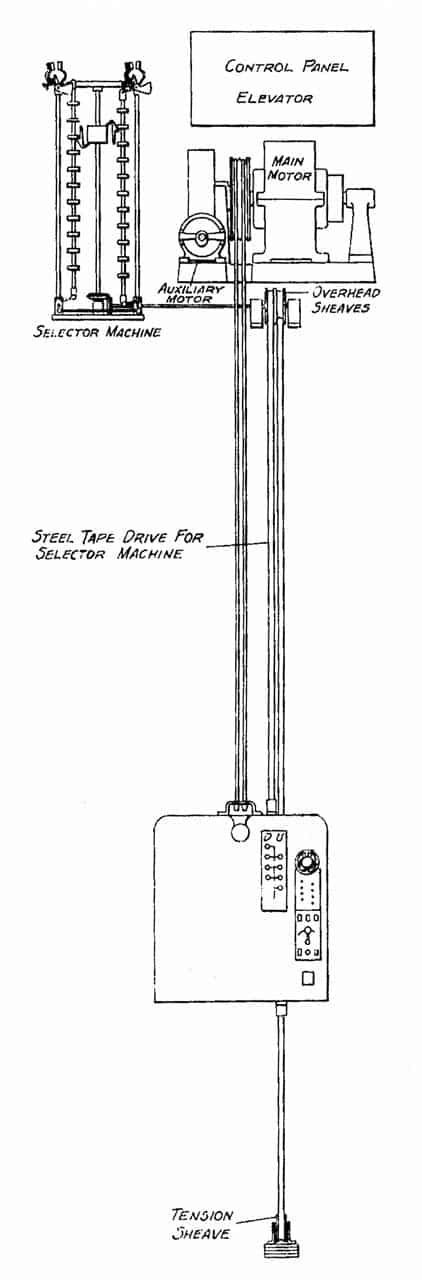
Another critical system component was the floor selector. The first operatorless elevators used drum machines with floor selectors that were connected to the motor via a chain that ran between a small sprocket-wheel mounted on the motor shaft and a larger sprocket-wheel mounted on the selector (thus, it could be calibrated to respond to the number of revolutions required to travel between landings). High-speed traction machines required a different solution. The floor selector was located adjacent to the main motor and was operated by means of two steel tapes attached to the car (Figure 4):
“One tape extends from the top of the car to an overhead sheave around which it is wound in a manner similar to the winding of a measuring tape. The other tape extends from the bottom of the car around a tension sheave and then up to a second overhead sheave upon which it is similarly but oppositely wound. The overhead sheaves cause the operation of the selector machine, one tape winding up as the other is unwound in the driving operation. This silent drive is as positive as a sprocket chain and is unaffected by sliding or stretching ropes.”[2]
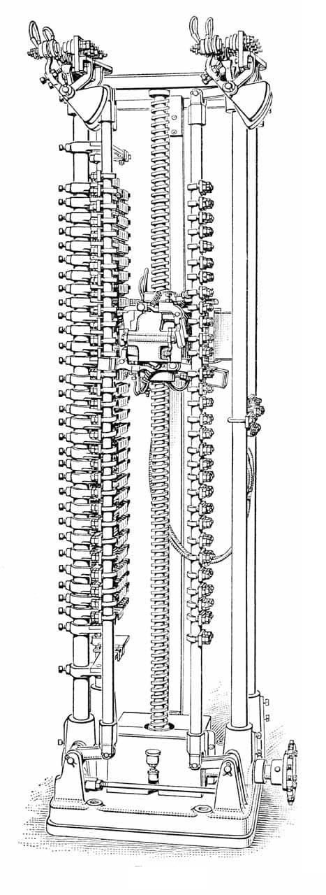
The overhead sheaves were connected to the floor selector via a shaft that employed a beveled gear connection to a screw-shaft that carried the selector switch, which interfaced with a series of switches, each of which corresponded to a given floor (Figure 5).
On May 21, 1925, Lindquist, Dunn and Larson filed two new patent applications that concerned a variation of their February 3 design (the patents were awarded in 1928 and 1933).[3] While the majority of the system’s components were identical to the earlier design, a key difference was that this system was fully operatorless (Figure 6). The operational features of the design were:
- ) to cause a pushbutton controlled car to stop automatically to pick up prospective passengers who desired to be carried in the direction in which the car was traveling.
- ) to have one car in a bank of elevators bear the brunt of the service when the demand was light, and to cause other cars to go into operation as the demand for service increased.
- ) to have only one car stop at a floor in response to the pushing of a button by a prospective passenger when several cars were in operation.
- ) to cause at least one car to continue in operation until response was had to all buttons pushed.
- ) to cause the cars to return to selected floors after a response was had to all pushbuttons operated.”[4]
Design changes that reflected passenger instead of operator control included a simplified car control panel that featured only floor buttons, a safety switch and a director switch. The car’s typical operation would have been as follows (assuming a 10-story building): If an up trip began at the first floor with passengers traveling to the second, fourth and fifth floors, after the last group of passengers had left the car, it would continue up to the 10th floor, at which point its direction would be automatically reversed by the director switch cams, and it would return to the first floor where it would remain parked until needed. This was typically described as a “collective control” system of operation.
A new feature was a “movable platform switch” or under-floor weight sensor that registered the presence of passengers in the car (Figure 7). When a car was parked at a landing, the doors were opened manually by a prospective passenger. When they entered the car, the platform switch detected their presence and, after the passenger had closed the car door, the platform switch sent a signal that caused the shaft door to close. When the passenger arrived at their destination and exited the car, the removal of their weight from the platform switch also caused the shaft door to automatically close.
The patent application for the third system designed by the Otis team was filed on May 13, 1925 (the patent was awarded in 1929).[5] The patent’s introduction provided a concise overview of the development of operatorless system components:
“As the art of electric elevator systems has developed, there has been an increasing tendency to relieve the operator in the car of various control operations. In some of the earlier systems, the starting and stopping of the car, the direction of travel of the car and the rate of acceleration and retardation were all controlled by the operator. Later the systems were arranged so that the rate of acceleration retardation was determined automatically by means controlled by the operator. Still later automatic means for bringing the car to an exact level with the landings in stopping were provided. Elevator systems have recently been developed wherein arrangements are provided for relieving the operator of determining the distance from the landing at which to return the car switch to “neutral” position to permit automatic retarding means and leveling devices to bring the car to rest at the landing. These developments greatly increased the efficiency of operation of elevator systems over systems of the earliest types.”[5]
In this patent, Lindquist, Dunn and Larson sought to increase the “efficiency of operation” in a system “particularly suitable for elevator service such as required in department stores.”[5] In this system, the role of the operator was limited to starting the car and opening and closing the car and shaft doors at each landing. Once started at the first floor, the car would automatically stop at each floor of a department store, allowing shoppers to exit and enter and allowing time for the operator to announce the types of merchandise found on a given floor. When the car reached the top floor, its direction was automatically reversed. The car control panel featured a “consecutive-stop switch” that initiated the elevator’s normative daily operation, a safety or emergency stop switch and a director switch. This system was given the (somewhat obvious or logical) designation of “department store control.”
The designs and systems found in this series of patents, all of whose applications were filed in 1925, highlight Otis’ continued focus on the development of operatorless elevators. This work also laid the foundation for a fundamental shift in elevator operation, which began in the mid-1920s. The next entry in this series of articles will address the application of these innovations in actual systems, how they operated and how they were advertised and promoted.
References
[1] David L. Lindquist, Edward L. Dunn and David C. Larson, Elevator System, U.S. Patent No. 1,767,891 (June 24, 1930); David L. Lindquist, Edward L. Dunn and David C. Larson, Switching Mechanism, U.S. Patent No. 1,767,892 (June 24, 1930); and David L. Lindquist, Edward L. Dunn and David C. Larson, Elevator System, U.S. Patent No. 1,904,646 (April 18, 1933).
[2] David L. Lindquist, Edward L. Dunn and David C. Larson, Elevator System, U.S. Patent No. 1,767,891 (June 24, 1930).
[3] David L. Lindquist, Edward L. Dunn and David C. Larson, Elevator System, U.S. Patent No. 1,694,712 (December 11, 1928) and David L. Lindquist, Edward L. Dunn and David C. Larson, Elevator System, U.S. Patent No. 1, 904,647 (April 18, 1933).
[4] David L. Lindquist, Edward L. Dunn and David C. Larson, Elevator System, U.S. Patent No. 1,694,712 (December 11, 1928).
[5] David L. Lindquist, Edward L. Dunn and David C. Larson, Elevator System, U.S. Patent No.1,717,046 (June 11, 1929).

Get more of Elevator World. Sign up for our free e-newsletter.
![]()


![]()