The Impact of EN 81-20 and EN 81-50 in Clips
May 1, 2018

This paper was presented at ELEVCON Madrid 2016, the International Congress on Vertical Transportation Technologies, and first published in IAEE book Elevator Technology 21, edited by A. Lustig. It is a reprint with permission from the International Association of Elevator Engineers IAEE (website: www.elevcon.com).
by Jesus Sanz and Jose Enrique Fernandez
In accordance with EN 81-20 and EN 81-50, friction forces exerted by clips on the guide rails have to be included in the guide-rail calculation. The fact of considering clip friction forces can result in requiring bigger guide-rail sizes with higher material cost. The use of existing clips in the market with very high friction forces, such as forged ones, will be limited to short buildings, whereas those with an elastic behavior can affect the guide-rail selection. This article contrasts conventional clips and the new concept of adjustable clips with ultra-low friction forces and high resistance that are suitable for EN 81-20 and EN 81-50 calculation.
1. Introduction
Despite the fact that riding-path deterioration occurs with the course of time (buckling of guide rails and large deformation of brackets have not been unknown effects of the interaction between the building and the riding path), previous versions of the norm EN 81 omitted the consideration of some vertical forces that take place in the riding path.
In contrast with former EN 81, EN 81-20 and EN 81-50 add the following factors when determining the vertical force Fv on the guide rails:
- Weight load of the guide rails
- Effect of building settlement or concrete shrinkage that causes push-through forces on the guide rails due to friction between clip and guide rail
This new calculation described in the standard invites the elevation industry to review and analyze the clips that are available in the market and to consider the development of new clips that offer an improved performance.
2. Interaction Between Clip and Guide Rail
There are two sorts of forces that act on the clip: lateral and vertical forces.
The traveling of the car or the counterweight, the operation of the safety gear or the effect of an earthquake cause lateral forces on the guide rails that must be finally withstood by the clips.
On the contrary, differential vertical displacements between building and guide rails (mainly due to building settlement, structural shrinkage or thermal differences) cause some vertical friction forces on the clips that must be finally borne by the guide rails and the joints, i.e., the riding path. These relative displacements occur in a timeframe that can range between six months to two years after building completion. A thorough calculation can be made to determine the decreasing ratio of a building, but it is not the purpose of this article, and a 0.1% reduction of the total building height is widely accepted. This figure gives a quick rule for estimating the maximum vertical relative displacement (a building 40 m tall has a maximum relative displacement of 40 mm; if 100 m tall, then it is 100 mm, etc.).
Somehow, the interacting forces between guide rail and clips demand different characteristics depending on the origin of the force. The force transmitted from the guide rail to the clip requires strength in the clip, whereas forces transmitted from the clips to the riding path require low friction force in the contact. The aim of both requirements is to preserve the structural integrity of the riding path.
Clips fix the guide rail, holding it from its base wings (Figure 1). The thickness of this feature of the guide rail has a ±0.75-mm tolerance that is a consequence of its manufacturing process (hot rolling mill). Summing up, clips must be able to clamp the rails on a feature, the total variation range of which can be 1.5 mm, and, in spite of this, they must guarantee the fulfillment of the strength and friction requirements in all cases.
3. Clips Available in the Market
It is possible to find many different types of clips in the market, but they can be classified in three main groups:
- Forged clips
- Sheet-metal-formed clips
- Adjustable clips

Table 1 assesses some characteristics of forged, sheet metal and SH adjustable clips.
3.1. Forged Clips
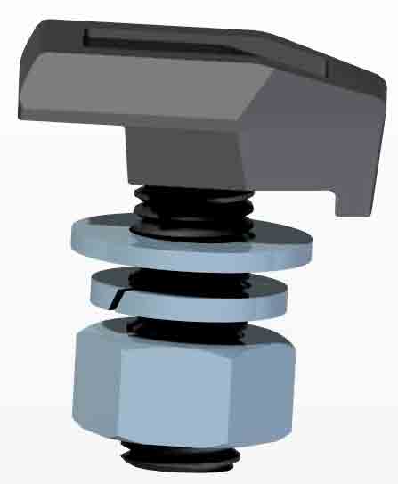
Forged clips are compact, and their main characteristic is that their resistance is very high (Figure 2).
They exert a very high normal force on the guide rail when they are installed. This high normal force results in a high vertical friction force between clips and guide rails.
This type of clip is suitable for fixing some elements that must be firmly fixed to the riding path (e.g., motor structures in machine-room-less applications) and for fixing the guide rails in low travel heights where the differential vertical displacements between clips and guide rails can be neglected. Nevertheless, its use is totally restricted in medium building heights.
EN 81-20 allows ignoring the push-through force for travel heights not exceeding 40 m, whereas it also requires adequate clearances to allow for the shrinkage of the building for these cases. Somehow, this fact can be understood as contradictory, and it still leaves open the question about why 40 m (40 mm of relative displacement, as has been said above) is the border for considering the push-through force. Considering this push-through force in all cases would be more consistent, no matter the building height, and would mandate using the clip that is really suitable for each installation according to a technical calculation.
3.2. SL Sheet-Metal Clips
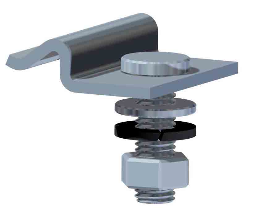
In contrast with forged clips, traditionally, sheet-metal clips have been considered sliding (SL) clips, and they were designed for reaching longer traveling heights (Figure 3).
In the past, SL clips were conceived as weaker clips compared to forged ones. Their plastic deformation should be automatically reached during its installation, and, thus, the normal force —and, subsequently, the friction force with the guide rail — should not vary significantly, despite the 1.5-mm total guide-rail base thickness variation.
Decades ago, when these clips were implemented in the elevator industry, just limited tests and theoretical calculations were carried out with hypothetical data and very simple elastoplastic models (elastic region and plastic region with Etan close to zero). Resulting data were accepted and have been considered valid until recently, but it is known that they can differ with reality due to various factors:
- Guide-rail base thickness tolerance is ±0.75.
- Normal clip tolerance for the contact point height is ±1 mm.
- Clip material yield limit variation from one clip to another
- Lateral pressure induced by the turning of the clip when tightening the nut
- Wrong installation (with gaps or with contact in the guide-rail radius)
- Sharp edges of bracket (bracket bends, slots, etc.)
It is important to draw attention to the material properties of the steel normally used in this type of clip, especially due to the fact that the clip material is expected to be operating in the plastic region.
ST37 (or its equivalent, S235JR) only defines the lowest allowed yield limit of the steel at 235 MPa, but the real yield limit can differ importantly from one batch to another.
The yield limit variation in 20 samples analyzed ranges from 113% to 164% with respect to the reference value of 235 MPa.
That is why different steels complying with ST37 behave similarly at the beginning, while the bolt is being tightened, because they start working in the elastic region. The difference arises once steel reaches the yield limit: the normal force does not continue increasing linearly, and the other steel is still elastic a little bit further. This would result in different normal forces on the guide rail and, therefore, different frictions and different resistances.
A deep analysis of the sheet-metal clip performance with all the variables mentioned above shows significant deviations between theoretical clip parameters and the real behavior of the clip.
Taking all this into consideration, it is necessary to define the resistance of this type of clip, considering the lowest allowed yield limit of its raw material, but the friction force should be defined considering the maximum yield limit that can be found. However, this maximum value is not available, as it is not specified in the raw-material definition of the standards.
3.3. SH Adjustable Clips
Aiming for ultra-low friction forces and high-resistance clips, a new concept arose with the adjustable clips (Figure 4).
SH-type clips are not supposed to exert any pressure on the guide rail when they are installed. With that purpose, they can be installed adopting the guide-rail dimensions at the point where they are assembled.
The advantage of not exerting any pressure on the guide rail — in fact, some residual normal force appears due to different imperfections — is that the friction force becomes very low.
Nevertheless, there are some important disadvantages of this type of clip, such as difficulty of a correct assembly, premature wearing of contact points under moderate lateral cyclical loads due to the inclined contact point, guide-rail disengagement risk, etc.
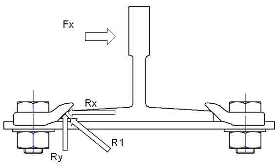
Basically, the inclined contact on the guide-rail radius converts the contact reaction (R1) into two component loads: one vertical (Ry) and another one horizontal (Rx) that tend to open the clips away (Figure 5). This causes a larger relative displacement at the contact between the clip and the guide rail that leads to premature wearing of the contact points when the clips undergo endurance tests, and, if the load is high enough, to a dangerous disengagement of the guide rail from the clips.
The results of endurance tests with Fx = 1,700 N, where the clips withstand millions of cycles, show that the SH clip wears out and presents the following clearances:
- Lateral gap: 0.5 mm after 150,000 cycles and 1 mm after 670,000 cycles
- Vertical gap: 0.5-mm gap after 620,000 cycles
4. State-of-the-Art Clips
The market is aiming for clips that combine the advantages mentioned above but reduce the disadvantages and the risks.
As a result of this need, new clips have been developed. SLS clips can be classified in the family of sheet-metal clips that exert low pressure, and SCA clips belong to the adjustable clip family.
4.1. SLS Sheet-Metal Low-Friction and Moderate-Resistance Clips
Ideally, the clip should exert a very low, controlled force on the guide rail when it is assembled. However, with standard sheet-metal clips, it means also having a low resistance for withstanding the lateral loads on the guide rail.
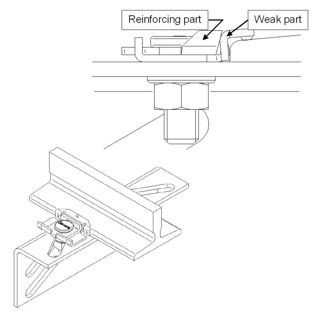
SLS clips bring a new concept of sheet-metal clips to the market. First, this new type of clip reduces the normal force at the contact with the guide rail by using a weakened clip. The fact of it being more flexible than a standard SL clip also reduces the influence of other factors (such as the clip and guide-rail tolerances). Secondly, the clip must be equipped with a backup mechanism or part that reinforces the weakened clip in case a lateral load on the rail exceeds the normal force exerted by the clip.
The target of these clips is to reach the resistance of SL clips but reduce their friction force. Figure 6 shows one of the available concepts for integrating the reinforcing mechanism in the clip.
This combination of differentiated behaviors (weaker while tightening but stronger when withstanding lateral loads) allows reducing, in practice, the theoretical friction force of SL clips, while their resistance parameters are maintained.
4.2. SCA Adjustable Clips
SCA clips offer ultra-low friction force, whereas they can withstand high lateral loads due to their robust design.
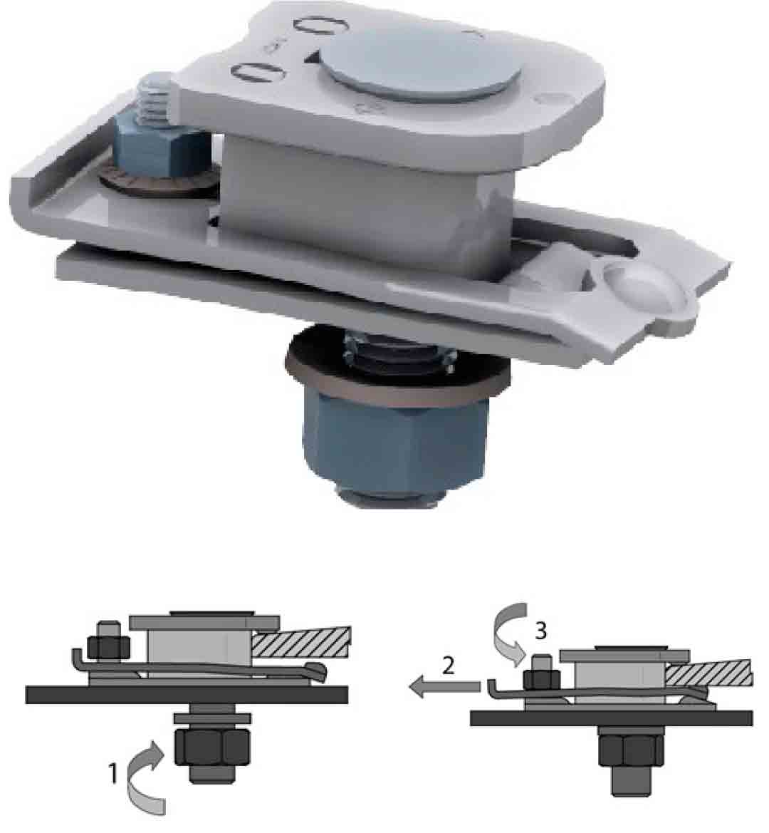
Being adjustable, their principle operation consists of holding the guide rail without exerting pressure on the contact points between clip and guide rail. They have a mechanism that can be easily adjusted during installation (Figure 7). First, the lateral adjustment is done by fixing the main bolt (1). Then, the adjusting part fits the guide-rail base thickness independently from the previous step (2 and 3). The differentiation of adjustments (guide-rail base width from guide-rail base height) eases the clip assembly and allows remarkably low friction forces.
In addition, the clip has the following advantages:
- Anti-turning interface with the bracket: the clip is kept horizontal without using extra tools.
- Riding-path quality preservation: the ultra-low friction force avoids stresses at the guide-rail joints that can modify the riding quality attained during the installation.
- Bracket inclination allowed: unevenness at the wall, especially those with concrete surfaces, can cause bracket inclination with respect to the guide rail. SCA clips perform invariably up to 3º bracket tilting.
- Cost: its simplicity and standardized manufacturing method result in a competitive price. Furthermore, the ultra-low friction force allows optimizing the brackets and, as a consequence, saves material.
5. Comparison Between Sliding Clips
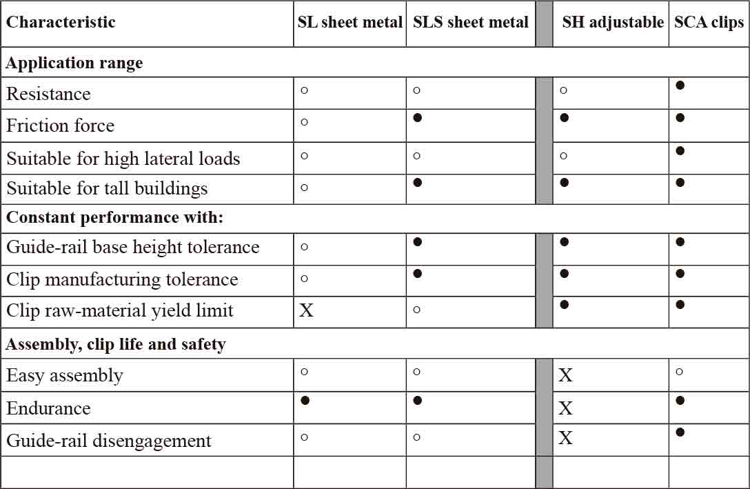
Table 2 compares conventional sheet-metal clips with SLS clips and conventional adjustable clips with SCA clips with the same criteria as in Table 1.
6. Conclusions
Low clip friction force is vital for preserving the riding-path quality over time. This characteristic is also beneficial for the guide-rail calculation due to the EN 81-20 requirement to consider the push-through force.
Although EN 81-20 allows ignoring the push-through force for travel heights not exceeding 40 m, it would be more coherent to always consider the push-through force, then use any clip that is valid according to the calculation.
The analysis of available clips in the market not only helps to know which clips are advantageous from the point of view of friction, but it is also an opportunity to assess other characteristics that are expected from the clip operation.
A comparison of different sliding clips draws the attention to new clip concepts that, apart from improving other aspects, also reduce the friction force.
On the one hand, SCA clips offer outstanding low friction forces and a very high resistance. On the other hand, SLS clips improve the friction performance of current sheet-metal clips available in the market, while keeping similar resistance levels.
Get more of Elevator World. Sign up for our free e-newsletter.
