Czech company showcases unique boat lift that met strict requirements as part of a modernization project.
submitted by EL-VY spol. s.r.o.
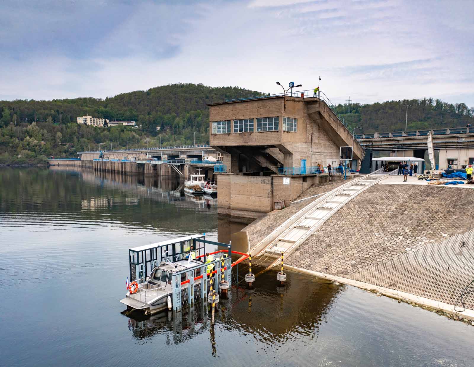
On the Orlická dam in the Czech Republic, a new boat lift for sports sailing was implemented on the 60th birthday of the waterworks. The modernization of the ship lift resulted in a complete replacement of technology and an increase in the transport capacity and parameters of the transported ships. The greatest demands from the Vltava Basin investor were placed on increasing the speed of ship transport, ensuring high operational reliability and, in addition to providing comfort, above all increasing the safety of transported persons. The general supplier of the ship lift was Metrostav a.s., and the carrier of the complete technological part is the Czech family company EL-VY spol. s.r.o. in Chrudim.
Ship Lift — A Unique Device
The boat lift at the Orlická dam is unique and cannot be legally classified under any standardized equipment such as an inclined lift or a ground cable car. For one run from the water surface of the Kamýk dam to the water surface of the Orlická dam, the boat lift rises about 70 m above the crest of the dam and then descends about 12 m to the level of the Orlík dam. The boat lift is used to transport smaller sports boats with the transport of people in the lift cabin. It generally provides transportation for all types of vessels, from punts, kayaks or Jet Skis to the largest sports motorboats and sailboats that move on waterways in the Czech Republic.
More than 10 designers from EL-VY spol. participated in solving the design problems and complications, including Koupený S.r.o. and ADIMG S.r.o. Their task was to double the lifting capacity of the lift to 6.6 t from the original 3.5 t, to extend the possible length of the transported ship from a maximum of 8 m to 10 m, to prepare for an increase in the maximum possible draft of ships from 1.2 m to 1.4 m and to solve the system of fixing the transported ship on the loading area of the elevator.
These difficult tasks were accomplished due to the existing construction of the track, which cannot be easily interfered with. The technology of the car can handle the required parameters, and when the range on the air side is deepened, it will be possible to transport boats with a draft of 1.4 m.
How Shipping Works
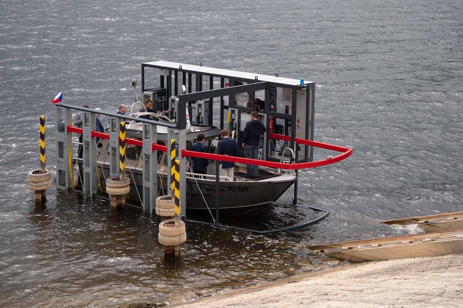
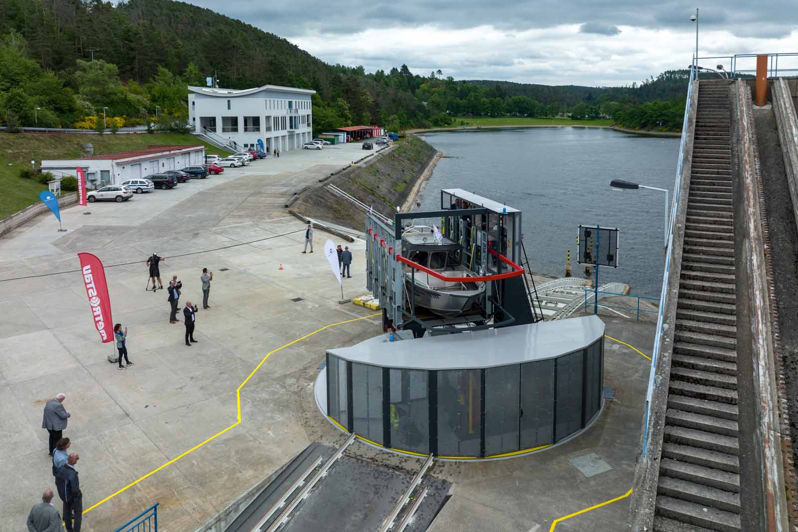
The boat lift at the Orlická dam works on the principle of a dry basket in which the transported boat is fixed. Each time the basket is completely submerged under the water surface so only the side legs of the car with the cabin remain above the surface. The ship floats into the “basket” area of the elevator cage, where it is positioned in the center of the loading area by means of electro-mechanical parallelograms and fixed by means of electrically controlled tension straps. The boat is transported with only the keel on the floor of the car. In terms of dynamic forces and limited sources of electric energy on the car, it is not possible to transport ships in a suspended position. The initial fixation of the boat and its tying to the car is done only lightly due to the necessity of hooking the lift cage up so that the boat lands with its keel on the bottom. Subsequently, the fixation is completed, and the crew leaves the vessel’s deck and passes into the elevator cabin behind the safety opening gates, which serve as cabin doors.
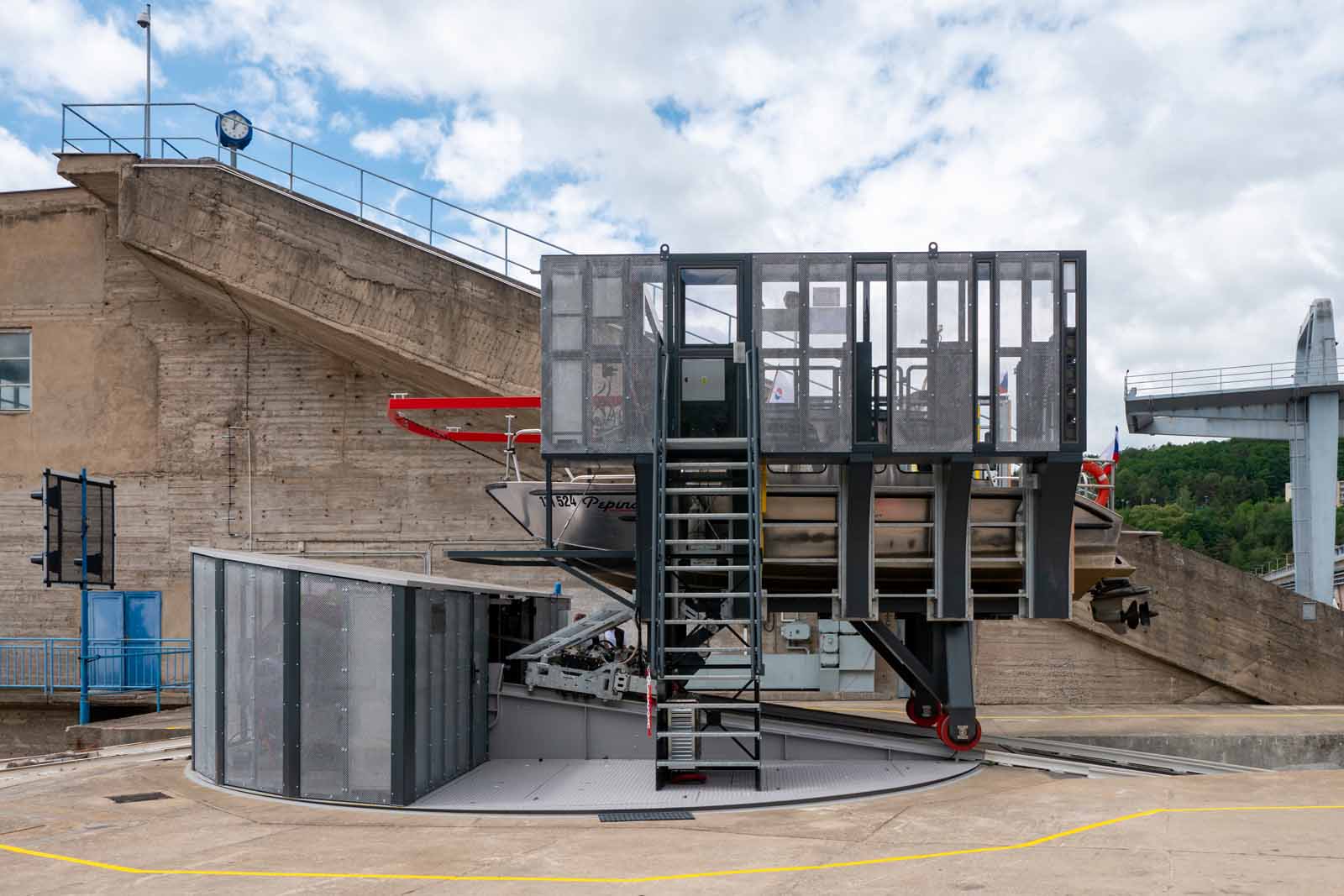
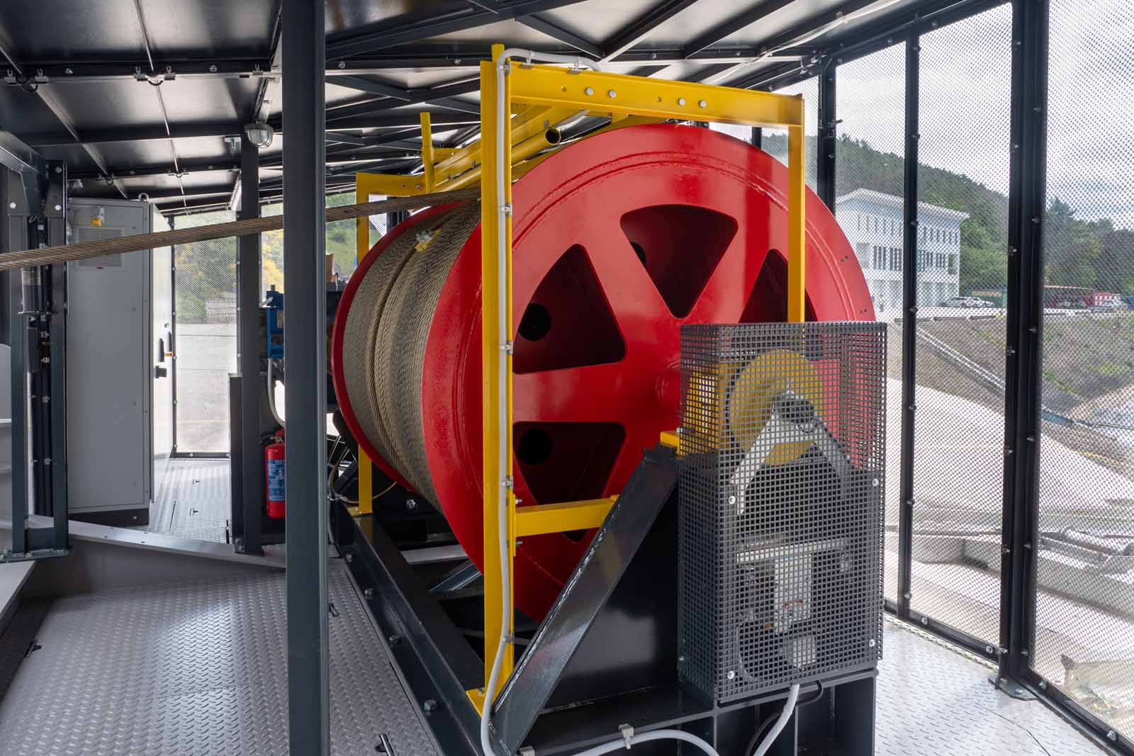
The cage is driven at a speed of 1 m/s to the crown of the embankment. The drive of the elevator is a drum on two cables in the engine room, which is located on the central turntable of the device. The elevator equipment is in a parked position on the turntable at the crown of the embankment.
It is on this turntable that the cage with the boat is pulled up to a distance of approximately 1 m between the car and the winding drum. After stopping the cage on the turntable and braking the system, the turntable is turned to the opposite face of the dam, and the cage with the boat is subsequently lowered to the water level on this side. The system has an automatic deceleration of the car before the water level, and after the platform enters the water and the boat is raised, it is released, and the crew gets on board and unties the boat. Meanwhile, the elevator driver releases all the mechanisms, and the boat subsequently backs up onto the water surface, and the ride is finished.
In season, the departing boat passes the waiting boat, which is signaled by a green light that the lift is ready for the next trip. The lift can handle up to 40 ships a day, six days a week.
Design Solution of Individual Parts of the Orlík Boat Lift
The boat lift completely replaced the original lift, which was put into operation in 1974. The mentioned basic concept of the boat lift was devised by experts from ČKD Slaný. E.g., it was not necessary to change anything to solve the problem of changing the slope of the track from 8° to 24° or the turntable drive concept. However, the elevator has undergone many improvements from increasing the maximum load capacity, introducing new mechanisms for stabilizing boats in the elevator cage to ensuring all the requirements of safe operation according to current European standards.
Boat Lift Design
From the point of view of the Vltava Basin investor, relatively high demands were placed on the design of the car and the engine room of the winch. In terms of finding a truly unique solution, the designer, architect Jiří Soukup from the studio SM architects s.r.o., was approached.
Based on several proposals with visualizations and many meetings, the final design solution of the elevator was chosen, which the architect called the “jewel of the dam.”

Safety Car Brake
From the beginning, the biggest design problem was the safety car brake, which has a similar function as an arrester and which has to stop the car if both cables break or if the maximum speed is exceeded by more than 20%. The brake must reliably stop both a fully loaded and an empty cage, both on a dry track and on one track submerged under water. This also results in high requirements for the choice of materials and their surface treatment. Where it was technologically possible, stainless steel was used.
The design problems of the mentioned brake lie in its specific operating conditions. This safety component is fully immersed in water twice each time the elevator travels. There is no similar brake design with such specific conditions on the market. The technicians of EL-VY Chrudim teamed up with technicians from Koupený S.r.o. for the development of a new, unique car brake for the ship lift at Orlická dam.
Technicians from EL-VY Chrudim provided legislative and scientific work to evaluate the braking properties that the brake must exhibit in terms of safety and, finally, its approval as a safety component. Construction and production activities were handled by technicians from the company Koupený S.r.o.
First, a one-tenth model of a car with a brake was produced, on which the dynamic characteristics of the braking effect were measured. Six types of brake shoes made of different materials and with different surfaces that “bite” into the rail head were tested. It was also determined with what force the brake jaws must be pressed against the rail head in order to achieve the desired braking effect. Approximately 60 measurements were taken, and from the results, the most suitable type of machined brake shoes was chosen, ensuring sufficient braking power on a wet track and a fully loaded elevator. At the same time, the braking system must not stop too quickly when the car is empty on a dry track. These two restrictions are contradictory and are clearly specified in the legislation for inclined lifts from the point of view of the safety of transported persons and loads. These conditions were properly tested on a sample of one finished brake and, subsequently, on an already finished lift, and they came out analogously according to the previously implemented model and in accordance with the legislation. The car brake was approved as a safety component of the boat lift at the Orlík dam.
Engine Room and Winding Mechanism
The new engine room on the turntable was built on the same floor plan dimensions as the original, and the space was defined by the size of the turntable. The engine room design was consulted with the studio SM architects s.r.o. and adjusted according to the technical assumptions given by the investor. All the equipment had to fit into the new engine room, even that which was originally located outside the engine room.
The new winding mechanism is housed in the same large space as the original, despite the fact that the performance of the device has been increased and the safety measure is much stricter than it was 50 years ago. The rope drum was a real nut — thanks to its dimensions and counter-rotating splines, the originally fixed and continuous shaft could not be used in the new machine due to lack of space inside the engine room. Additionally, the new disc brake and the new gear motor required a different solution to the shaft construction. The drum production technology was consulted with the company ADIng, s.r.o.
Power Unit Braking System
The elevator has multiple safety systems. In addition to the vehicle brake described above, the drive has three other brakes.
The P.I.V. hydraulically released safety disc brake acts directly on the drum. This is the so-called main brake, which in the event of a loss of electrical power or interruption of the safety discharge opens the throttle valve and stops the drum with a controlled deceleration, even if the transmission shaft breaks.
Between the engine and the gearbox there is a NORD safety disc brake with electrical release and an original electromagnetic engine brake installed at the end of the engine.
Each of the brakes listed below is rated to stop a fully loaded car traveling at full speed if all other brakes fail.
The brake system is equipped whenever the safety circuit is interrupted, such as in particular speeding sensed by a standard certified speed limiter located directly on the winding drum, safety switches sensing the release of one rope or the loss of secure transmission between the machine room and the elevator car.
Stabilization of Ships in the Ship Lift Cage
On the part of the investor, great demands were placed on devising an efficient, fast, reliable and universal system of ship stabilization for transporting ships by ship lift. From the point of view of the demands of the public on the quantity of transported ships, it was necessary to devise a system of rapid stabilization of ships without exact specifications for EL-VY Chrudim technicians in terms of the exact type of ships and their shapes. Such an assignment is impossible: No one can say which ship will arrive.
The technicians of EL-VY Chrudim teamed up with the technicians from Koupený S.r.o., and they began to devise and refine this assignment. Together, they toured shipyards and studied all the possible shapes of ships that could come to be transported on the new ship lift.
On the basis of these studies, the Koupený workshop created a detailed assignment, which was presented at KD and, after approval, a quarter model of the ship with prototypes of stabilization mechanisms was realized, all in real 1:1 scale. This model was presented to client Metrostav a.s. and investor Povodí Vltava a.s. The system was approved, and all the components on the car went into production.
In the original lift, the transported ship was manually tied to the side posts, firmly attached (welded) to the structure of the ship’s carriage. The mooring was carried out by the captain of the vessel who was also responsible for it. This process was quite demanding and lengthy. Existing new systems fix the ship without the participation of the captain and are controlled from the cabin by the elevator operator.
Opposite pairs of rigid parallelograms controlled by electric drives via chain synchronization gears are mounted on both ends of the loading area of the truck. In the folded position (when the ship is driven into the elevator carriage), the mechanisms are hidden in the support columns. After the boat is driven onto the carriage, the parallelograms extend up to 650 mm on each side and clamp the bow and stern of the boat from both sides. In order not to damage the ship’s lining, the pressure arms of the mechanism are equipped with plastic strips. The size of the extension and the strength of the pressure is chosen by the elevator operator.
Between the parallelograms on similar supporting columns on each side of the cart, three mechanisms with textile straps are fixed. At one end, the straps are fixed to the center of the carriage, and at the other end, they are introduced into winding drums driven, via chain gears, by means of electric drives. When winding the straps on the drums, these straps become shorter and gradually “lay” on the sides of the boat. This system makes it possible to gently hug practically any shape of the ship’s side without damaging it (abraded, dented, etc.). The amount of tension, and thus the strength of the pressure, is chosen by the elevator operator. The courts return to their starting position by rewinding the drums with the help of spring mechanisms, which return the free courts to the grooves prepared on the bottom of the carriage. Without the return springs, the courts would “flail” freely on the bed of the cart and could catch on a boat approaching the cart.
The drives of both fixation mechanisms are two-speed. Activation of each mechanism is possible separately, and the return to the initial position is performed automatically for all mechanisms with one command.
Power Source on the Ship Lift Car
The above ship stabilization mechanisms are powered by a total of 10 asynchronous motors with fr. converters. These drives need considerable electrical energy, next to which the energy requirements for the elevator control system on the car are negligible. It was, therefore, necessary to solve the problem of supplying the car with sufficient electrical energy without a hanging cable or electric trolley.
EL-VY Chrudim technicians solved the problem by implementing a charging docking station on the turntable, where every time a car is accepted on the turntable, the batteries are immediately recharged. The batteries are used to power all electrical appliances while the car is driving outside the turntable. However, this method was insufficient for the expected load of the elevator.
The car-battery charging system was supplemented by charging from the movement of the car itself using two alternators for trucks. By means of a chain transmission, rotational energy is transmitted from the upper wheel of the car under the cabin to the gearbox, at the output of which the belts of the mentioned alternators are driven. The first sailing season showed that this method of recharging the batteries on the car is sufficient, and the operation of the car was not interrupted due to the need to recharge the batteries.
The Original Solution — Slope of the Runway, Turntable and Elevator Drive
The elevator track has two slopes of 8º and 22º with transition arches with a radius of 180 m; on both sides of the embankment, there are trough-shaped concrete foundations to which two pairs of type Xa rails are anchored. The inner rail with a gauge of 2,420 mm is used for the movement of the trolley tread and the upper wheels of the trolley along the entire length of the track, including the suspended trolley with a vehicle brake. The lower wheels of the trolley travel on them only at a slope of 8º. On transition arcs and a track slope of up to 22º, the lower wheels of the trolley travel on the outer rails with a gauge of 3,120 mm, which smoothly rise above the level of the upper edge of the inner rails from the beginning of the transition arcs so at the beginning of the track with a slope of 22º, the height difference is 865 mm. This is necessary to maintain the horizontal plane of the car platform on both slopes of the track.
The existing rails were completely replaced with new ones. The complete replacement of the rails was carried out by ZETA Chrudim, s.r.o.
The elevator drive was increased to double the load capacity, and the concept of a winding drum with two ropes running along a helix away from each other in the first roll and opposite each other in the second roll was adopted from the original solution. In terms of current legislation, the ropes have a diameter 12 times larger than the minimum calculated, and it was also necessary to install a device preventing or guarding a rope jump into three layers.
The concept of the turntable drive remained the same as the original, namely the drive with positive contact using a toothed pinion and tubular or spline gearing. The drive itself was designed completely new with a new suspension system that ensures significantly quieter operation than the original turntable.
Elevator Control and Signaling
The boat lift is controlled by the driver, who is responsible for the safe operation of the lift by holding the control joystick in the direction of travel, i.e., driving with the hold of the person in charge. From this point of view, the lift driver has the right to refuse to transport the ship, e.g., in the case of a captain under the influence of alcohol.
If the driver suspects that the captain has not provided true information about the total weight of the boat and exceeds the maximum allowed weight, he can start the mode of weighing the boat while driving. The car goes into weighing mode and, while driving slowly, weighs the ship with an accuracy of +/- 15%. This information is sufficient for the eventual exceeding of the total load of the elevator by a maximum capacity of +15%, and the operation of the elevator is stopped by the system; only driving down back to the water level is allowed.
In terms of signaling, the car is equipped with a visualization of the car’s position on the track with the presentation of other basic information that can be passed on to the transported crew.
From the point of view of ensuring safety and proving possible unpleasant situations, a camera is installed on the car, which records what is happening in the cabin of the ship’s elevator during the entire process of carrying out the ship’s transportation. If necessary, this record is available from the operator of the Vltava Basin.
Get more of Elevator World. Sign up for our free e-newsletter.
