Escalators and moving walks
by Nimish Deshpande
Background
First published as IS 4591:1968, the Indian Standard on Escalators has been in existence for many years. The standard was limited to escalators and included very few important safety requirements for these pieces of equipment. In 2020, after more than 20 years of deliberation and alignment with international standards, the Bureau of Indian Standards (BIS) published the first revision of the Indian Standard on Escalators and Moving Walks (IS 4591:2020). The standard now covers escalators and moving walks. This standard has been aligned with EN 115: 1995+A1:1998+A2:2004, “Safety Rules for the Construction and Installation of Escalators and Passenger Conveyors.” This is of significant importance, as it helps bring construction and installation requirements for escalators and moving walks to an international standards level.
Scope
This standard is applicable for all new escalators and moving walks (pallet or belt type). It deals with all significant hazards, hazardous situations and events relevant to escalators and moving walks when they are used as intended and under conditions of misuse reasonably foreseeable by the manufacturer. The standard does not deal with hazards arising from seismic activities. It is not applicable to escalators and moving walks manufactured before the date of its publication. It is, however, recommended that existing installations be adopted to this standard.
The latest publication of IS 4591 — Escalators and Moving Walks (First Revision) is divided into three sections under Part 1, namely:
- IS 4591 (Part 1/Section 1): 2020 — Safety Requirements
- IS 4591 (Part 1/Section 2): 2020 — Guide for Planning and Selection
- IS 4591 (Part 1/Section 3): 2020 — Inspection and Testing
IS 4591 (Part 1/Section 1 ): 2020 — Safety Requirements
Escalators and moving walks shall comply with the safety requirements and/or protective measures described in this section. In addition, escalators and moving walks shall be designed for relevant — but not significant — hazards, which are not dealt with in this standard. Certain escalators and moving walks are subject to special operational and environmental conditions, such as being directly exposed to the weather or an explosive atmosphere or, in exceptional cases, serving as emergency exits, appropriate design criteria, components, materials and instructions for use should be used that satisfy the particular condition. The standard defines the requirement for following components:
Supporting Structures (Truss) and Encloser
All mechanically moving parts of the escalator or moving walk shall be completely enclosed within imperforate panels or walls. Exempt from this are the accessible steps, accessible pallets, accessible belt and parts of the handrail that are available for user. The supporting structure shall be designed in such a way that it can support the dead weight of the escalator or moving walk, plus a rated load of 5000 N/m2. Based on the rated load, the maximum calculated or measured deflection shall not exceed 1 / 750 of the distance between the supports.
Steps, Pallets, Belts
The standard provides the dimensional, structural design and test requirements for escalator steps and moving walk pallets/belts. The important design criteria defined is that the materials shall retain their strength characteristics during their specified life cycle, considering environmental conditions such as temperature, ultraviolet radiation, humidity and corrosion. The steps, pallets and belt shall be designed to withstand all possible loading and distortion effects that may be imposed by the tracking, guiding and driving system during normal operation and shall be designed to support an equally distributed load corresponding to 600 N/m2.
Under-testing tests are divided into the static test and dynamic test. The static test includes tests for steps, step risers, pallets and belts with maximum acceptable deflection under the loading conditions. The dynamic test includes tests for loading and torsion for steps and pallets.
Driving Machine
A driving unit shall not operate more than one escalator or moving walk. The nominal speed shall not deviate by more than + 5 % at nominal frequency and nominal voltage. The nominal speed of escalator shall not exceed:
- 0.75 m/s for an escalator with an angle of inclination up to 30º and
- 0.50 m/s for an escalator with an angle of inclination of more than 30º up to 35º
The nominal speed of a moving walk shall not be higher than 0.75 m/s. Deviating from the above, nominal speed up to 0.90 m/s is permitted, provided the width of the pallets or the belt does not exceed 1.10 m and, at the landings, the pallets or belts move horizontally for a length of at least 1.60 m before entering the combs. The above-mentioned requirements do not apply to moving walks with acceleration paths or moving walk systems with direct transition to moving walks traveling at different speeds.
Braking System
Operational Brake
Escalators and moving walks shall have a braking system that brings them to rest with a uniform deceleration, and remain stationary. There shall be no intentional delay in the application of the braking system.
The braking system shall operate automatically in the event of loss of:
- Voltage supply and
- Voltage supply to the control circuits
Brake Load and Stopping Distance for Operational Brake
Determination of Brake Load for Escalators
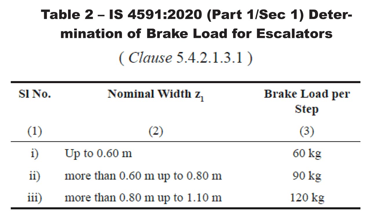
The number of steps to be considered is determined by the rise of the escalator divided by the maximum visible height of the step riser. For purposes of this test, the total brake load is allowed to distribute over two-thirds of the number of steps thus obtained.
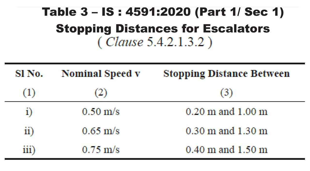
Stopping Distance for the Escalator
The stopping distances for unloaded and downward-moving loaded escalators shall be as given in Table 3:
Determination of Brake Load for Moving Walks
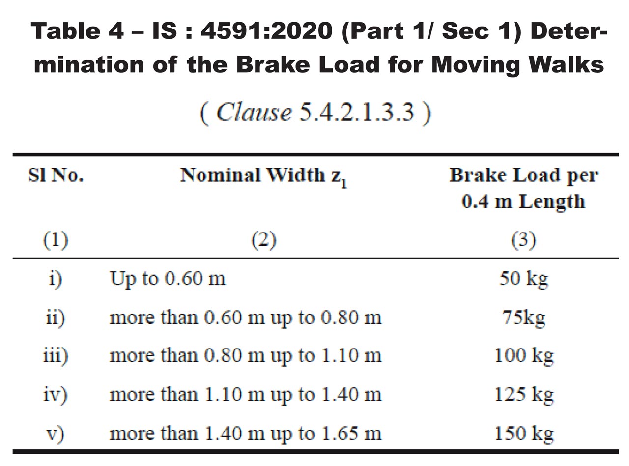
In determining the brake load for moving walks, which in their length overcome several inclinations (differences in level), only the downward running section shall be considered.
Stopping Distance for Moving Walks
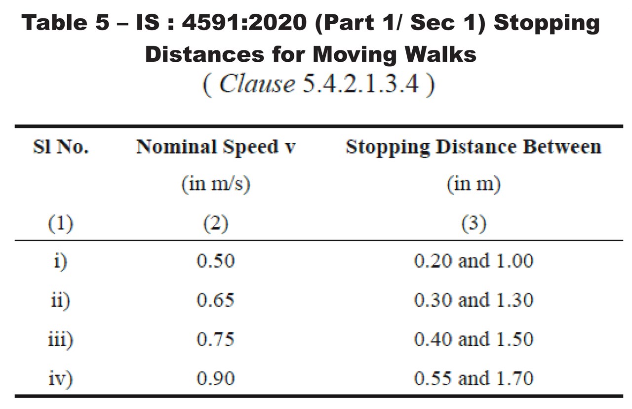
The stopping distance for unloaded and horizontally or downward-moving loaded moving walks shall be as given in Table 5:
Auxiliary Brake
Escalators and inclined moving walks shall be equipped with an auxiliary brake if the:
- Connection between the operational brake and the driving sprockets of the steps/pallets or the drum of the belt is not accomplished by shaft, gear wheel, multiplex chains or more than a single chain.
- Operational brake is not an electromechanical brake
- Rise of the escalator exceeds 6 m
- Escalators and moving walks are used for public transport; then, for all rises less than 6 m
Steps and Pallet Drive
Escalator steps shall be driven by at least two chains, of which at least one shall be located on each side of the step.
Pallets of the moving walks are permitted to be driven by only one chain if the parallel movement of the pallets in the usable area is ensured by other mechanical measures. Step chain design shall be of nominally infinite fatigue life. The safety factor against breaking each chain shall be at least five.
Belt Drive
The factor of safety of the belt, including splicing, shall be at least five. The belt shall be driven by drum and be tensioned continuously and automatically.
Balustrade
Balustrades are installed on each side of an escalator and moving walk. In the inclined section, the vertical height from the step nose or pallet surface of the belt to the top of the handrail shall not be less than 0.90 m and not exceed 1.0 m. The balustrade shall have no parts on which a person would normally stand. Appropriate measures shall be taken to discourage people from climbing on the outside of the balustrades if there is a danger of people falling from them.
Skirting
The skirting shall be vertical, plain and butt-jointed. On escalators, the possibility of entrapment between skirting and steps shall be minimized. For this purpose, the standard defines four conditions to be fulfilled:
- Sufficient rigidity of skirting
- Horizontal clearance that does not exceed 4 mm at either side and 7 mm for the sum of clearance measured at both sides at two directly opposite points
- Installation of skirt deflectors according to defined design requirements in the clause
- Use of suitable material or suitable type of lining underneath the deflector device to achieve a coefficient of friction for leather, PVC and rubber less than 0.45
Newel
The newel, including the handrail, shall project beyond the comb intersection line by at least 0.60 m in the longitudinal direction.
Handrail System
On the top of each balustrade, a handrail moving in the same direction and at a speed with a tolerance of –0% to +2% relative to the actual speed of the steps, pallets or belt under normal operating conditions shall be provided.
A handrail speed-monitoring device shall be provided and shall stop the escalator or moving walk in the event of a handrail speed deviation of more than -15% of the actual speed for more than 15 s while the escalator or moving walk is in motion. The handrail profile and guides on the balustrade shall be formed or enclosed in such a way that the possibility of pinching or trapping of fingers or hand is reduced. Distance between the center lines of the handrails shall not exceed the distance between the skirting by more than 0.45 m. The lowest point of entry of the handrail into the newel shall be at a distance from the finish floor level not less than 0.10 m and not exceeding 0.25 m. At the point of entry of the handrail into the newel, a guard shall be installed to prevent pinching of fingers and hands. A switch shall be provided. The handrail shall be guided and tensioned in such a way that it shall not leave its guide during normal use.
Landings
The landing area of escalators and moving walks (that is, the comb plate and floor plate) shall have a surface that provides a secure foothold for a minimum distance of 0.85 m measured from the root of the comb teeth.
At the landings, the escalator steps shall be guided in such a way that the front edge of the steps leaving the comb and the rear edges of the steps entering the comb are moving horizontally for a length of at least 0.80 m measured from the root of the comb teeth. At nominal speeds above 0.50 m/s and not more than 0.65 m/s or rises above 6 m, this length shall be at least 1.20 m measured from the root of the comb teeth. At nominal speed above 0.65 m/s, this length shall be at least 1.60 m measured from the root of the comb teeth.
At the upper landings of moving walks with an inclination of more than 6º, the pallets or the belt shall move for a length of at least 0.40 m at a maximum angle of 6º before entering or after leaving the comb. Combs shall be fitted at both landings to facilitate the transition of users. They shall be easily replaceable. Combs shall have such a design that, upon trapping foreign bodies, either their teeth deflect and remain in the mesh with the grooves of the steps, pallets or belt, or they break.
Machinery Spaces, Driving Station and Return Station
These rooms/spaces shall be used only for accommodating the equipment necessary for the operation, maintenance and inspection of the escalator or moving walk. Effective protection and guards shall be provided for moving and rotating parts if they are accessible and dangerous. In machinery spaces, especially in driving and return stations inside the truss, space with a sufficiently large area shall be kept free from permanently installed parts of any kind. The size of the standing area shall be at least 0.30 m2 and the smaller side shall be at least 0.50 m in length.
Electrical Installations and Appliance
The electrical installation of escalators and moving walks shall be designed and manufactured to ensure protection against hazards arising from electrical equipment or caused by external influences on it, provided the equipment is used in an application for which it is made and is adequately maintained. Therefore, electrical equipment shall comply with the requirements of the Indian Electricity Act and related rules. Please refer to the standard for detailed requirements.
Protection Against Electric Faults: Controls
The standard lists the faults envisaged, namely:
- Absence of voltage
- Voltage drop
- Loss of continuity of conductor
- Fault to earth of circuit
- Short circuit or open circuit
- Non-attraction or complete attraction of the moving armature of a contactor or relay
- No separation of the moving armature of a contactor or relay
- Non-opening of contact
- Non-closing of contact
- Phase reversal
In the case of safety switches, the non-opening of the contact need not be considered. The requirements of safety switches are defined further in the clause of the standard.
The fault to earth of a circuit, in which there is an electric safety device, shall cause immediate stopping of the drive machine. Requirements of electrical safety devices are defined further in the clause of the standard.
Verification of the Safety Requirements and Protective Measures
The method to be used to verify conformity to the safety requirements and measure by test, measurement, calculation and visual inspection is described with the help of Table 7: Method to be Used to Verify conformity to the Requirements in IS 4591, Part 1, Section 1, 2020. The manufacturer is required to maintain the verification records.
Conclusion
Safety requirements for the various systems, sub-systems and components of escalators and moving walks are specified in detail under Section 1. Compliance with these will ensure safe and uniform equipment, regardless of manufacturer. It is recommended that one goes through the original standard to understand the requirements in detail.
IS 4591 (Part 1/Section 2): 2020 — Guide for Planning and Selection
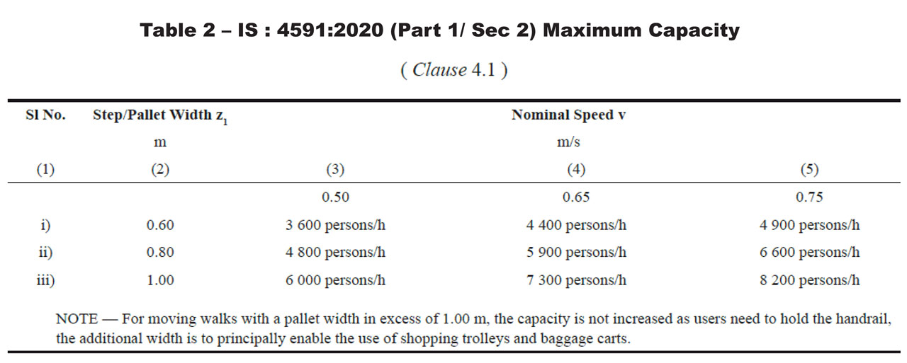
This section provides a guideline for the planning and selection of escalators and moving walks. Specifications of escalators and moving walks are defined by the maximum number of persons that can be carried in 1 h. This standard provides a table to specify maximum capacity.
The use of shopping trolleys and baggage carts on escalators is unsafe and shall not be permitted, primarily due to foreseeable misuse, overloading and width restrictions. The use of suitably designed trolleys and baggage carts on moving walks is permitted. These shopping trolleys or baggage carts shall conform to the moving walk design:
- The shopping trolley or baggage cart design shall ensure safe and correct loading.
- The maximum weight for a shopping trolley or baggage cart shall be 160 kg when loaded.
- Shopping trolleys or baggage carts should automatically lock themselves on the inclined part of moving walks.
- Shopping trolleys or baggage carts shall be fitted with a braking or blocking system.
- Shopping trolleys or baggage carts shall have deflectors (bumpers) to reduce the risk of clamping.
Building Interfaces
Owner of installation has obligation to fulfil these Building Interfaces requirements. These requirements are defined to ensure Safe Passenger travel on Escalator and Moving Walks.
- Free Space for users
- The clear height above the steps of the escalator or pallets or belt of the moving walks at all points shall be not less than 2.30 m
- For escalators arranged adjacent to one another, the distance between the handrails shall not be less than 160 mm.
- If the horizontal distance between the outer edge of the handrail and any obstacle is less than 400 mm, a vertical deflector of a height not less than 300 mm shall be provided.
- There should be enough space for passenger movement at the entry floor and the destination floor to prevent overcrowding. The exit passage at the destination floor shall have adequate capacity for smooth flow of the people discharged by the escalator.
- Successive escalators and moving walks without intermediate exits shall have the same capacity.
- Where it is possible for people to come into contact with the outer edge of the handrail at a landing and can be drawn into a hazardous situation, proper, permanent barriers shall be provided.
- The surrounds of the escalator or moving walk shall be illuminated, especially in the vicinity of the combs.
- Machinery Spaces Outside the Truss
- Safe access to persons to machinery spaces shall be provided.
- Machinery spaces shall be lockable and accessible only to authorized persons.
- Machinery spaces shall be provided with permanent lighting.
- Emergency lighting shall be installed to allow safe evacuation of all personnel working in any machinery spaces.
- Dimensions of machinery spaces shall be sufficient to permit easy and safe work on equipment.
- In machinery spaces, clear height, under no circumstances, shall be less than 2.0 m.
- Electric Power Supply
Arrangement shall be made between the owner and the manufacturer regarding electric supply and the electric protection requirement.
Documentation
The standard also provides guidelines for the type of documentation and contents of the documentation for clarity between the owner and the manufacturer.
Marking
At at least one landing, details of installation must be marked. This assists in the traceability of the installation and equipment.
Conclusion
The provisions of Section 2 should help both the owner and manufacturer clearly differentiate responsibilities and tasks to achieve better coordination during installation.
IS 4591 (Part 1/Section 3 ):2020 — Inspection and Test
This section of the standard deals with the inspection to be carried out for escalators and moving walks before their first use, after major modification and at regular intervals. Such inspections and tests should be carried out by competent persons.
Constructional Inspection and Acceptance Inspection and Test
The constructional inspection and acceptance inspection and test shall be carried out at the jobsite upon completion of the escalator or moving walk. For this test, the data specified in 6.2 of IS 4591 (Part 1, Section 1) should form part of a pre-completion test sheet. Construction inspection consists of the examination of the completed installation for conformity with the required data and in regard to proper workmanship, as specified in the standard.
The acceptance inspection and test comprises:
- Overall visual inspection (as per Annex A of Section 3)
- Functional tests
- Tests of electric safety devices with regard to their effective operation
- Tests of brake(s) of the escalators or moving walks under no load for compliance with the prescribed stopping distances
- Measurement of insulation resistance of the different circuits between conductors and earth
Inspection and Test After Major Modification
A major modification is a change of the location, speed, electric safety devices, braking system, drive, control, step band, truss and balustrade. Wherever applicable, the principles set forth for the constructional inspection and acceptance inspection and test should apply to the new environmental conditions, modified components and other components affected. The replacement of parts with parts of the same design is not considered a major modification.
Conclusion
The provisions of Section 3 should help both the regulatory inspection authorities and the manufacturer clearly identify the inspection and test requirements for acceptance of the installation for public use.
Disclaimer
This article is written in good faith to educate and make people aware of the first revision of IS 4591:2020. The article means to summarize and does not contain all the information that may be relevant for any given condition. For this reason, users are advised to refer to the original standard and text. All tables and figures are taken from IS 4591:2020, published by the BIS. Further, the views expressed are personal to the author. The author/publisher or the organization where the author may be employed shall not be held responsible for any action taken by any individual based on the information contained in this article.
Get more of Elevator World. Sign up for our free e-newsletter.


